3Com 4500 Getting Started Manual
Switch 4500 family switch 4500 26/50-port switch 4500 pwr 26/50-port
Hide thumbs
Also See for 4500:
- Manual (942 pages) ,
- Configuration manual (742 pages) ,
- Getting started manual (88 pages)
Table of Contents
Advertisement
Quick Links
Advertisement
Table of Contents

Related Manuals for 3Com 4500


Summary of Contents for 3Com 4500
-
Page 1: Switch 4500 Family
SuperStack Switch 4500 Family Getting Started Guide Switch 4500 26-Port (3CR17561-91) Switch 4500 50-Port (3CR17562-91) Switch 4500 PWR 26-Port (3CR17571-91) Switch 4500 PWR 50-Port (3CR17572-91) http://www.3com.com/ Part No. DUA1756-1AAA01 Published August 2005 ®... -
Page 2: Superstack
3Com Corporation reserves the right to revise this documentation and to make changes in content from time MA 01752-3064 to time without obligation on the part of 3Com Corporation to provide notification of such revision or change. 3Com Corporation provides this documentation without warranty, term, or condition of any kind, either implied or expressed, including, but not limited to, the implied warranties, terms or conditions of merchantability, satisfactory quality, and fitness for a particular purpose. -
Page 3: Table Of Contents
Switch 4500 — Rear View Detail Power Socket Open Book Warning Labels Redundant Power System Socket Default Settings NSTALLING THE WITCH Package Contents Choosing a Suitable Site Rack-mounting Rack Mounting the Back of your Switch 4500 (PWR only) 4500 F AMILY... - Page 4 Connecting a Redundant Power Supply to your Switch 4500 PWR Specifying the Redundant Power System Connecting the Switch to the Redundant Power System Connecting the Earthing Cable RPS LED Using Power over Ethernet Placing Units On Top of Each Other...
- Page 5 Setting Up Command Line Interface Management using SSH Setting Up Web Interface Management Pre-requisites Web Management Over the Network Setting Up SNMP Management V1 or V2 Pre-requisites Default Users and Passwords REATING A TACK How to Interconnect Units Guidelines For Interconnecting Units Unit Numbering within the Stack ROBLEM OLVING...
- Page 6 PC-AT Serial Cable Modem Cable Ethernet Port RJ-45 Pin Assignments ECHNICAL PECIFICATIONS Switch 4500 (26 Port) Switch 4500 (50 Port) Switch 4500 PWR (26 Port) Switch 4500 PWR (50 Port) Earthing Lead BTAINING UPPORT FOR Register Your Product Purchase Value-Added Services...
-
Page 7: About This Guide
Release Notes. BOUT ® SuperStack 3 Switch 4500 26-Port (3CR17561-91) ® SuperStack 3 Switch 4500 50-Port (3CR17562-91) ® SuperStack 3 Switch 4500 PWR 26-Port (3CR17571-91) ® SuperStack 3 Switch 4500 PWR 50-Port (3CR17572-91) UIDE... -
Page 8: About Your Cd-Rom
Screen displays This typeface represents information as it appears on the Syntax Commands Online documentation for the Switch 4500 — refer to Related Documentation on page 9 for details. A link to 3Com Network Director software. A number of other useful links. -
Page 9: Related Documentation
SuperStack 3 Switch Configuration Guide This guide contains information on the features supported by your Switch and how they can be used to optimize your network. It is supplied in PDF format on the CD-ROM that accompanies the Switch. SuperStack 3 Switch Quick Reference Guide This guide contains: a list of the features supported by the Switch. -
Page 10: Accessing Online Documentation
■ ■ ■ Example: Part Number DUA1756-1AAA01 SuperStack 3 Switch 4500 Family Getting Started Guide Page 21 Release Notes These notes provide information about the current software release, including new features, modifications, and known problems. The Release Notes are supplied in hard copy with your Switch. - Page 11 Documentation Comments Please note that we can only respond to comments and questions about 3Com product documentation at this e-mail address. Questions related to technical support or sales should be directed in the first instance to your network supplier.
- Page 12 BOUT UIDE...
-
Page 13: Introducing The Super Stack 3 Switch 4500 Family
NTRODUCING THE UPER AMILY This chapter contains introductory information about the Switch 4500 and how it can be used in your network. It covers summaries of hardware and software features and also the following topics: About the Switch 4500 ■... -
Page 14: About The Switch 4500
† Combo SFP and 1000BASE-T SFP transceiver installed in last two 1000BASE-X SFP slots The Switch 4500 Family provides high-performance workgroups with a backbone to server connection. You can also add the Switch 4500 Family to any SuperStack For information about using the software features of the Switch, refer to the “Command Reference Guide”... -
Page 15: Summary Of Hardware Features
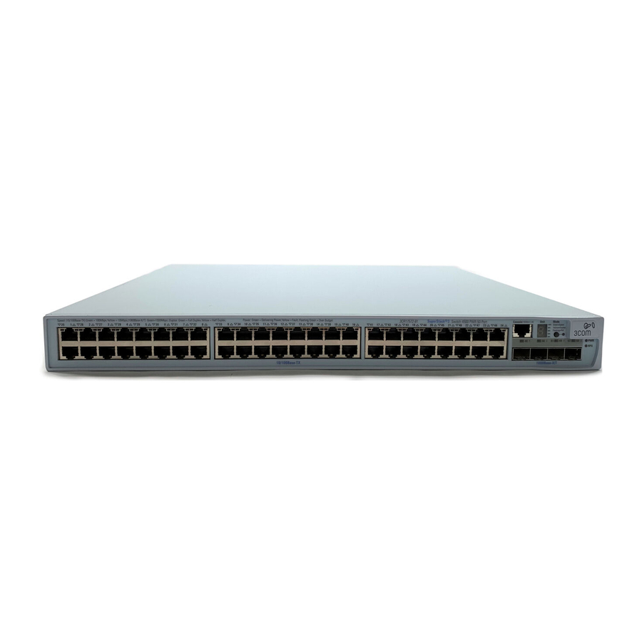
Table 4 Hardware Features Switch 4500 — Front View Detail Figure 1 Switch 4500 26-Port — front view Port Status LEDs Speed: (100Base-TX) Green = 100Mbps Yellow = 10Mbps (1000Base-X) Green = 1000Mbps Yellow = 10/100Mbps Duplex: Green = Full Duplex, Yellow = Half Duplex... -
Page 16: 10Base-T/ 100Base-Tx Ports
Figure 2 Switch 4500 50-Port — front view Speed:Green = 100Mbps, Yellow = 10Mbps Duplex:Green = Full Duplex, Yellow = Half Duplex Figure 3 Switch 4500 26-Port PWR - front view Port Status LEDs Speed: (100Base-TX) Green = 100Mbps Yellow = 10Mbps... -
Page 17: 1000Base-X Sfp Ports
Only one port in each pair can be enabled at any one time. The Switch 4500 50 Port and Switch 4500 PWR 26 and 50 Port have 4 x 1000BASE-X SFP ports. The first two SFP ports support all 3Com gigabit SFP modules. -
Page 18: Unit Led
“Solving Problems Indicated by LEDs” on page 70 LEDs Table 5 lists LEDs visible on the front of the Switch, and how to read their status. For information on using the LEDs for problem solving, see “Solving Problems Indicated by LEDs” on page 70. - Page 19 Duplex (3CR17571-91 and 3CR17572-91 only) Green Full duplex packets are being transmitted/received on the port. Yellow Half duplex packets are being transmitted/received on the port. Yellow flashing Port failed POST. No link is present. Switch 4500 — Front View Detail...
-
Page 20: Switch 4500 - Rear View Detail
Sie die in Anhang A dieses Handbuchs aufgeführten Sicherheitshinweise lesen. ADVERTENCIA: Antes de instalar o extraer cualquier componente del Switch 4500 Family o de realizar tareas de mantenimiento, debe leer la información de seguridad facilitada en el Apéndice A de esta guía. 4500 F... -
Page 21: Redundant Power System Socket
Provides supplemental power for PoE ports (up to 15.4w on all ports) and System Socket redundant power for powered devices and the Switch itself. Default Settings Table 6 shows the default settings for the Switch 4500 Family: Table 6 Default Settings Feature Automatic IP Configuration... - Page 22 1: I HAPTER NTRODUCING THE Feature Traffic Prioritization Port Security Configuration Save and Restore 4500 F UPER TACK WITCH AMILY Switch 4500 All ports prioritize VoIP traffic (LAN and IP). All ports set to “best effort” for all other traffic.
-
Page 23: Installing The Switch
Switch 4500. It covers the following topics: Package Contents ■ Choosing a Suitable Site ■ Rack-mounting ■ Connecting a Redundant Power Supply to your Switch 4500 PWR ■ Placing Units On Top of Each Other ■ The Power-up Sequence ■ SFP Operation ■... -
Page 24: Package Contents
HAPTER NSTALLING THE AVVERTENZA: Informazioni di sicurezza. Prima di installare o rimuovere qualsiasi componente dal Switch 4500 o di eseguire qualsiasi procedura di manutenzione, leggere le informazioni di sicurezza riportate nell'Appendice A della presente guida per l'utente. OSTRZEŻENIE: Informacje o zabezpieczeniach. Przed instalacją lub usunięciem jakichkolwiek elementów z product lub przeprowadzeniem... -
Page 25: Choosing A Suitable Site
Water or moisture cannot enter the case of the Switch. Air flow is not restricted around the Switch or through the vents in the side of the Switch. 3Com recommends that you provide a minimum of 25mm (1in.) clearance. Air temperature around the Switch does not exceed 40 The air is as free from dust as possible. -
Page 26: Rack-Mounting
HAPTER NSTALLING THE Rack-mounting The Switch 4500 is 1U high and will fit in most standard 19-inch racks. CAUTION: Disconnect all cables from the Switch before continuing. Remove all self adhesive pads from the underside of the Switch if they have been fitted. -
Page 27: Rack Mounting The Back Of Your Switch 4500 (Pwr Only)
Rack Mounting the To rack mount the back of your Switch 4500 (PWR only): Back of your Switch 4500 (PWR only) 1 Locate a rear rail bracket over the mounting holes on one side of the rear of the Switch, as shown in Figure 8. -
Page 28: Connecting A Redundant Power Supply To Your Switch 4500 Pwr
■ ■ ■ You may need this information if you contact 3Com Technical Support. Connecting a The Switch 4500 PWR 26-Port and 50-Port have a -48V DC Redundant Redundant Power Power Supply socket. Supply to your Switch 4500 PWR WARNING: The installation of the Redundant Power Supply (RPS) should only be carried out by properly trained and qualified personnel. - Page 29 WARNING: The characteristics of the Switch 4500 DC supply input are given in Appendix C on page 119. The Switch 4500 PWR units can be powered in three different ways: AC Mains only — does not offer any power redundancy. If the AC ■...
-
Page 30: Specifying The Redundant Power System
-48V DC RPS that meets the requirements defined in Appendix C on System page 119. For an approved vendor list, more details about purchasing the 3Com recommended RPS and a full set of requirements go to: http://www.3Com.com/RPS The 3Com recommended RPS generates -48V DC power using power supply units (or rectifiers). -
Page 31: Connecting The Switch To The Redundant Power System
Redundancy The -48V DC power distribution provides the mechanism to connect to the Switch 4500 PWR. The distribution consists of a number of circuit breakers and connection terminals for the positive (common) and negative -48V outputs. Each Switch 4500 PWR must be individually connected to a circuit breaker terminal. - Page 32 Figure 9 shows how to connect the power supply to the RPS socket in the back of the Switch. Use the cable tie supplied with your Switch to support the cable at the rear of the RPS connector as shown.
-
Page 33: Connecting The Earthing Cable
The recommended cable length should not exceed 3 meters (9.84 feet). RPS LED The RPS status LED on the front of the Switch 4500 PWR indicates the status of the RPS and AC supplies as shown in Table 11. Table 11 RPS LED Colors... -
Page 34: Placing Units On Top Of Each Other
■ The Switch supports resistor detection according to IEEE 802.3af and pre-standard detection methods. The Switch 4500 supports 3Com 802.3af equipment. For the latest list of supported devices, refer to the product page on the 3Com web site at http://www.3com.com/... -
Page 35: The Power-Up Sequence
The Power-up The following sections describe how to get your Switch 4500 Sequence powered-up and ready for operation. Powering-up the Use the following sequence of steps to power-up the Switch. Switch 4500 1 Plug the power cord into the power socket at the rear of the Switch. - Page 36 MDI port, you need to use a standard straight-through cable. See Table 13. 3Com recommends that you use at least Category 5 twisted pair cable — the maximum segment length for this type of cable is 100 m (328 ft.).
-
Page 37: Choosing The Correct Cables For The 1000Base-X Sfp Ports
Choosing the Correct The 1000BASE-SX SFP transceiver supports a direct connection to a Cables for the multi-mode fiber-optic cable. The 1000BASE-LX SFP transceiver supports 1000BASE-X SFP Ports a direct connection to single-mode and multi-mode fiber-optic cables. The 1000BASE-LH70 SFP transceiver supports a direct connection to a single-mode fiber-optic cable and the 1000BASE-T SFP transceiver uses Category 5 copper cabling with RJ-45 connectors and supports segment lengths of up to 100 m (328 ft). -
Page 38: Sfp Operation
2 3CSFP93-4500 1000BASE-T SFPs are supplied with the Switch 4500 50 port (for ports 51/52), the Switch 4500 PWR 26 (for ports 27/28) and Switch 4500 PWR 50 port (for ports 51/52). The Switch 4500 26 port is not supplied with 3CSFP93-4500 transceivers. -
Page 39: Inserting An Sfp Transceiver
If the SFP transceiver is faulty, it will not operate within the Switch. See “Solving Hardware Problems” on page 71. 3Com recommends that you only use Gigabit Ethernet SFPs supplied by 3Com. If the SFP transceiver is invalid it will not be recognized by the Switch. Inserting an SFP... -
Page 40: Removing An Sfp Transceiver
3 Pull the wire release lever toward you to release the catch mechanism; the transceiver will then easily slide out. Packing and This section describes how to correctly package your Switch 4500 should Shipping the Switch you need to return it to 3Com. - Page 41 Packing and Shipping the Switch 4500 Figure 11 Correct Orientation When Packing the Switch 4500 Polystyrene Supports Cable Packaging Back Front Panel Side Panel Side Switch Unit...
- Page 42 2: I HAPTER NSTALLING THE WITCH...
-
Page 43: Setting U P For Management
ETTING To make full use of the features offered by your Switch, and to change and monitor the way it works, you have to access the management software that resides on the Switch. This is known as managing the Switch. -
Page 44: Methods Of Managing A Switch
Refer to “Setting Up Command Line Interface Management” on page 58. There are two main views in the CLI: User View — this view is shown when you first connect to the Switch and shows basic information about operation and statistics. The prompt for user view is <4500>. -
Page 45: Command Line Interface Management Using Ssh
Methods of Managing a Switch Command Line The Switch 4500 supports Secure Shell (SSH) version 2.0, allowing secure Interface access to the Command Line Interface of the Switch. Management using If you use SSH to administer your Switch and the network traffic is intercepted, no passwords or configuration information will be visible in the data. -
Page 46: Setting Up Overview
ETTING P FOR Setting Up This section gives an overview of what you need to do to get your Switch Overview set up and ready for management when it is in its default state. The whole setup process is summarized in Figure 16. Detailed procedural steps are contained in the sections that follow. -
Page 47: Ip Configuration
(Static IP addresses are necessary to ensure that the Switch is always allocated the same IP information.) For most installations, 3Com recommends that you configure the Switch IP information manually. This makes management simpler and more reliable as it is not dependent on a DHCP or BootP server, and eliminates the risk of the IP address changing. -
Page 48: Preparing For Management
“SuperStack 3 Switch Command Reference Guide” on the CD-ROM that is supplied with the Switch or on the 3Com Web site. ANAGEMENT your network uses DHCP to allocate IP information, or flexibility is needed. -
Page 49: Manually Configuring Ip Information
(this example describes a local connection to the console port, rather than one via a modem). You can do this whilst the Switch is offline, that is, before you connect the Switch to a network, or whilst the Switch is online, that is, connected to a network. - Page 50 ■ Refer to the documentation that accompanies the terminal emulation software for more information. 3 Power up the Switch. The Power on Self Test (POST) will now be performed. Setting Up the Switch with IP Information You are now ready to manually set up the Switch with IP information using the command line interface.
- Page 51 2 At the login and password prompts, enter press Return and at the password prompt press Return again. If you have logged on correctly, <4500> should be displayed as shown in Figure 18. Once you have logged in you will automatically be in User View.
-
Page 52: Connecting To A Front Panel Port
ETTING P FOR If you do not intend to use the command line interface via the console port to manage the Switch, you can disconnect the serial cable and close the terminal emulator software. Connecting to a Front To set up your Switch manually you can, alternatively, make a connection Panel Port to a front panel port. - Page 53 Using the Web Interface 1 Power-up the Switch. This takes approximately one minute. 2 Open a suitable Web browser and enter the IP address of your Switch in the Address field. If there is no response, wait for one minute then re-enter the IP address.
- Page 54 3 At the login and password prompts, enter admin as your user name and press Return at the password prompt. If you have logged on correctly, <4500> is displayed as shown in the example in Figure 20. ANAGEMENT is: Telnet xxx.xxx.xxx.xxx...
-
Page 55: Viewing Automatically Configured Ip Information
Switch as the configuration is not saved automatically when the Switch is powered down. The initial set up of your Switch is now complete and the Switch is ready for you to set up your chosen management method. See “Methods of Managing a Switch”... -
Page 56: Using 3Com Network Director
DHCP or BootP server. If your network does not have a DHCP or BootP server, the workstation running 3Com Network Director must be on the same subnet as the Switch, because Auto-IP addresses are non-routable. Connecting to the... - Page 57 3 At the login and password prompts, enter press Return at the password prompt. If you have logged on correctly, <4500> is displayed as shown in the example in Figure 21. Figure 21 User View Login 4 Enter display ip interface br to view a summary of allocated IP addresses.
-
Page 58: Setting Up Command Line Interface Management
Overview manage the port data. There are two types of user interfaces: AUX User Interface — used to log in to your Switch via the console port. A fabric can have up to eight AUX user interfaces. VTY User Interface — used to Telnet to the Switch. The Switch can have up to five VTY user interfaces. -
Page 59: Setting Up Command Line Interface Management Using Ssh
6 If you have logged on correctly, the Switch you wish to manage is displayed as <4500> (as shown in l on page 51). Setting Up This section describes how you can set up Command Line Interface Command Line management using SSH over a network. -
Page 60: Setting Up Web Interface Management
5 Open an SSH session and access the Switch using the Switch’s IP address and port number. The first time you connect to the switch the client will ask you to confirm that the host key is correct for the device. -
Page 61: Web Management Over The Network
Management Protocol (SNMP) can manage a Switch if: ■ ■ You can use the 3Com Network Director application that is available from the 3Com website to provide SNMP management for your Switch. If you use 3Com Network Director it automatically loads the correct MIBs and necessary files onto your workstation. -
Page 62: Pre-Requisites
Passwords command line interface, or to change the default passwords, you need to log in with a valid user name and password. The Switch has three default user names, and each user name has a different password and level of access. - Page 63 Use the admin default user name (no password) to login and carry out initial Switch setup. To set a password for the admin user in the CLI, enter the following from system view: [4500]local-user admin <cr> [4500-luser-admin]password simple xxxxxxxx (where xxxxxxxx is your chosen password). Save the configuration in the User View.
- Page 64 3: S HAPTER ETTING P FOR ANAGEMENT...
-
Page 65: Creating A Stack
You can interconnect your Switches to create a stack using a standard 1000 Mbps Ethernet connection. It is not possible to create a stack by interconnecting a 3Com Switch 4500 with any other 3Com device. This section assumes you have either set up your units for management as detailed in Chapter 3 “Setting Up for Management”... -
Page 66: Guidelines For Interconnecting Units
As with all Switch 4500 CLI commands, the format for entering a command that is port specific is x/y/z, where x = unit number, y = module number (in the case of the Switch 4500 this will always be 0), z = port number. -
Page 67: Unit Numbering Within The Stack
Unit Numbering When a stack is created using the Switch 4500 the unit numbering can within the Stack be determined in two ways. ■ 3Com recommends that you manually assign the unit IDs within the stack if you wish to have predictability of knowing which units have which IDs at all times. - Page 68 4: C HAPTER REATING A TACK...
-
Page 69: Problem Solving
■ If you experience a problem that is not listed here, it may be included in the Support section of the SuperStack 4 Switch 4500 Command Reference Guide on the CD-ROM that accompanies your Switch. For Technical Support information, see Appendix D. -
Page 70: Solving Problems Indicated By Leds
HAPTER ROBLEM OLVING Solving Problems If the LEDs on the Switch indicate a problem, refer to the list of suggested Indicated by LEDs solutions below. The PWR LED does not light Check that the power cable is firmly connected to the Switch and to the supply outlet. -
Page 71: Solving Hardware Problems
Fan failure could potentially reduce the lifetime of the Switch. The monitoring system polls the fan status at periodic intervals while the unit is powered up. If one fan has failed in the Switch, a warning message will be generated in the following ways: ■... - Page 72 RPS supply. 4 If another fan failure warning message is generated via the Command Line Interface or the Web interface, return the unit to 3Com. Unit fails, no SNMP fan failure message is received 1 Power cycle the unit. To do this, remove and reconnect the AC mains supply.
-
Page 73: Solving Communication Problems
IP Addressing To be managed correctly, each device on your network (for example a Switch or Hub) must have a unique IP address. IP addresses have the format n.n.n.n where n is a decimal number between 0 and 255. An example IP address is 192.168.100.8. - Page 74 ‘in house’ only. A device is connected to a Switch 4500 PWR but power is not being supplied If power is not being supplied to a device connected to a Switch 4500 PWR, you should do the following checks: ■...
-
Page 75: Solving Stack Formation Problems
Solving Stack If you are having problems with correctly forming a stack, first ensure that Formation Spanning Tree is enabled. If it is enabled, do the following: Problems 1 Power off all units in the stack. 2 Check all the cable connections in the stack. 3 Check the ports have been enabled as stack ports. - Page 76 5: P HAPTER ROBLEM OLVING...
-
Page 77: Upgrading Software
PGRADING This chapter describes how to upgrade software to your Switch 4500. It covers the following topics: The Contents of the Executable File ■ Upgrading from the Command Line Interface ■ Upgrading from the Bootrom Interface ■ Bootrom Upgrade ■... -
Page 78: The Contents Of The Executable File
Bundled files with the extension NetMan.zip, can be used to upgrade your Switch using the 3Com Network Director Agent Update. Any attempt to upgrade individual .web, .btm or .app files using 3Com Network Director will fail. These files should be used to upgrade your Switch as described below. - Page 79 To delete files from the list for the remaining units in a fabric, replace unit1 with unit2 (on the next line) and so on for each Switch in the fabric. 4 The /unreserved option will cause the file to be deleted from both the flash and the recycle-bin.
-
Page 80: Tftp
Replace unit1 with unit2 and so on for each Switch in the fabric. 3 To back up the Web user interface file on each Switch in the fabric, enter: copy unit1>flash:/s3p03_01_00.zip unit1>flash:/030100http.zip Replace unit1 with unit2 and so on for each Switch in the fabric. - Page 81 Replace unit2 with unit3 and so on for each Switch in the fabric. 3 To copy the new Web user interface file to each Switch in the fabric, enter: copy unit1>flash:/ Replace unit2 with unit3 and so on for each Switch in the fabric.
-
Page 82: Ftp (Via A Network Port)
OFTWARE To set the remaining Switches in the fabric to load the new bootrom firmware, replace unit1 with unit2 and so on for each Switch in the fabric. 3 You will now need to reboot the fabric for the changes to take effect. The Switch will upgrade the bootrom firmware and boot from the specified software .app file. -
Page 83: Xmodem (Via The Console Cable)
XModem (via the To upgrade software to your Switch via XModem, do the following: console cable) 1 From the User View, enter: xmodem get unit1>flash:/3ComOScfg.def The following information is displayed: xmodem is a slow transfer protocol limited to the current speed settings of the auxiliary ports. -
Page 84: Upgrading From The Bootrom Interface
This section describes how to upgrade your Switch from the Bootrom Bootrom Interface Interface. Introduction When the Switch is running the initial boot phase via the console, the following prompt is displayed with a five second countdown timer: Press CTRL-B to enter Boot Menu... 4 followed by a password prompt:... - Page 85 This option displays all the files in flash and also indicates the file that the Switch is currently set to boot from (marked with an asterisk). A ‘b’ by the file number indicates the file is a backup boot file.
-
Page 86: Tftp
Load File name: Switch IP address: Server IP address: 3 Enter the file name, Switch IP address and Server IP address to display the following: Are you sure to download file to flash? Yes or No(Y/N) 4 Enter y and the following information is displayed to indicate the file is... -
Page 87: Xmodem
Server IP address: FTP User Name: FTP User Password: 3 Enter the file name, Switch IP address, Server IP address and FTP user name and password to display the following: Are you sure to download file to flash? Yes or No(Y/N) -
Page 88: Bootrom Upgrade
6 Repeat steps 1 to 5 for each of the remaining files. Bootrom Upgrade This section describes how to indicate which file the Switch is to boot from once the software has been loaded. 1 From the Boot menu, select option 2 to display the following: Select applicaton file to boot: 1. -
Page 89: Bootrom Upgrade Via Tftp
Load File name: Switch IP address: Server IP address: 3 Enter the file name, Switch IP address and Server IP address to display the following: Are you sure to update your bootrom? Yes or No(Y/N) 4 Enter y and the following information is displayed to indicate the file is... -
Page 90: Bootrom Upgrade Via Xmodem
Server IP address: FTP User Name: FTP User Password: 3 Enter the file name, Switch IP address, Server IP address, FTP user name and password to display the following: Are you sure to update your bootrom? Yes or No(Y/N) 4 Enter y and the following information is displayed to indicate the file is... - Page 91 4 Press Enter to start the download. The following information is displayed: Now please start transfer file with XMODEM protocol If you want to exit, Press <Ctrl+X> Loading ...CCCCCCCCCCCCCCCCCCCCCCCCCCCCC 5 As the file is downloading, start the XModem send file process with terminal emulation software, such as Microsoft HyperTerminal.
- Page 92 6: U HAPTER PGRADING OFTWARE...
-
Page 93: Safety Information
You must read the following safety information before carrying out any installation or removal of components, or any maintenance procedures on the Switch 4500. WARNING: Warnings contain directions that you must follow for your personal safety. Follow all directions carefully. -
Page 94: Power Cord Set - Japan
WARNING: Installation and removal of the unit must be carried out by qualified personnel only. WARNING: If installing the Switch 4500 together (one on top of the other) with SuperStack II or SuperStack 3 units that are shallower than the 4500, the Switch 4500 unit must be installed below the shallower units. - Page 95 U.S.A. and The cord set must be UL-approved and CSA certified. ■ Canada The minimum specification for the flexible cord is: ■ No. 18 AWG Type SV or SJ 3-conductor The cord set must have a rated current capacity of at least ■...
- Page 96 † Impédance à la terre. WARNING: U.K. only: If connecting a modem to the console port of the Switch 4500, only use a modem which is suitable for connection to the telecommunications system. WARNING: RJ-45 Ports. These are shielded RJ-45 data sockets. They cannot be used as standard traditional telephone sockets, or to connect the unit to a traditional PBX or public telephone network.
-
Page 97: L'information De Sécurité Importante
à un personnel qualifié. AVERTISSEMENT: Si vous entassez l'unité Switch avec les unités SuperStack 4 Hub, l'unité Switch 4500 doit être installée en dessous des unités Hub plus étroites. AVERTISSEMENT: Vous devez mettre l’appareil à la terre (à la masse) ce groupe. - Page 98 A: S PPENDIX AFETY NFORMATION AVERTISSEMENT: Cordon électrique: Il doit être agréé ans le pays d'utilisation: AVERTISSEMENT: Votre unité d'alimentation vous a été livrée avec un film plastique qui protège la fiche d'alimentation en courant du système de redondance d'alimentation (48V CC). Si vous connectez une alimentation CC à...
- Page 99 L’information de Sécurité Importante AVERTISSEMENT: France et Pérou uniquement: Ce groupe ne peut pas être alimenté par un dispositif à impédance à la terre. Si vos alimentations sont du type impédance à la terre, ce groupe doit être alimenté par une tension de 230 V (2 P+T) par le biais d'un transformateur d'isolement à...
- Page 100 à la terre, conformément à la norme IEC 60950-1/UL 60950-1/EN 60950-1. AVERTISSEMENT: Ces instructions doivent être lues conjointement avec les caractéristiques de l'alimentation CC du Switch 4500 fournies en annexe C, Spécifications techniques. AVERTISSEMENT: Vous devez respecter les recommandations du fabricant lors du branchement du câble au module RPS.
-
Page 101: Wichtige Sicherheitsinformationen
VORSICHT: Alle Verfahren die in dieser Anleitung beschrieben werden gelten für alle Modelle, sofern nicht anders angegeben. Wo eine Vorgehensweise für die Schalter 4500 26 und Schalter 4500 50 gilt wird nur der Begriff Schalter verwendet. Diese Anleitung ist für Netzwerkadministratoren vorgesehen, die für die Installation und das Einstellen von Netzwerkkomponenten verantwortlich sind;... - Page 102 A: S PPENDIX AFETY NFORMATION VORSICHT: Europe ■ ■ VORSICHT: Der Betrieb dieses Geräts erfolgt unter den SELV-Bedingungen (Sicherheitskleinstspannung) gemäß IEC 60950. Diese Bedingungen sind nur gegeben, wenn auch die an das Gerät angeschlossenen Geräte unter SELV-Bedingungen betrieben werden. VORSICHT: RJ-45-Porte. Diese Porte sind geschützte Datensteckdosen. Sie dürfen weder wie normale traditionelle Telefonsteckdosen noch für die Verbindung der Einheit mit einem traditionellem privatem oder öffentlichem Telefonnetzwerk gebraucht werden.
- Page 103 Switch an die positive (gemeinsame) Klemme der RPS und die negative Klemme am Switch an die negative (gemeinsame) Klemme der RPS angeschlossen wird. VORSICHT: Bei den Switches 4500 PWR wird auf allen vorderen Ports Power over Ethernet unterstützt. Diese Ports dürfen nur für die Ethernet-Verkabelung im gleichen Gebäude verwendet werden.
-
Page 104: Información De Seguridad Importante
ADVERTENCIA: Si instala el 4500 en una pila con unidades SuperStack II o SuperStack 3 que son más estrechas que el 4500, la unidad 4500 debe instalarse debajo de las unidades más estrechas. ADVERTENCIA: La unidad debe tener toma de tierra (conectado a tierra). - Page 105 †Impédance à la terre. ADVERTENCIA: Sólo para el Reino Unido: si conecta un módem al puerto de consola del 4500, utilice sólo un módem que sea adecuado para la conexión con el sistema de telecomunicaciones. ADVERTENCIA: Puertos RJ-45. Son conectores de datos RJ-45 blindados.
- Page 106 SELV sin toma de tierra según IEC 60950-1/UL 60950-1/EN 60950-1. ADVERTENCIA: Estas instrucciones deben leerse junto con las características de la entrada de suministro de CC del Switch 4500 del Apéndice C, Especificaciones técnicas. ADVERTENCIA: al conectar el cable al RPS deberán seguirse las recomendaciones del fabricante.
-
Page 107: Importanti Informazioni Di Sicurezza
AVVERTENZA: Le operazioni di installazione e rimozione dell'unità devono essere eseguite esclusivamente da personale qualificato. AVVERTENZA: Se si installa lo 4500 in uno stack con unità SuperStack II o SuperStack 3 più strette del modello 4500, posizionare lo 4500 sotto tali unità. - Page 108 †Impédance à la terre. AVVERTENZA: Solo Regno Unito. Se si collega un modem alla porta Console dello 4500, utilizzare solo un modem idoneo per il collegamento con il sistema di telecomunicazioni. AVVERTENZA: Le porte RJ-45 sono prese dati RJ-45 schermate. Non è...
- Page 109 AVVERTENZA: queste istruzioni devono essere lette insieme alle istruzioni di sicurezza e installazione fornite con l'RPS. AVVERTENZA: se si accende uno Switch 4500 da un RPS, l'unità deve disporre di messa a terra. Per accendere lo switch, è possibile collegare il cavo di alimentazione all'unità, collegare il terminale di terra situato sul...
-
Page 110: Wa¿Ne Informacje O Zabezpieczeniach
OSTRZEŻENIE: Instalacja i demontaż urządzenia mogą być wykonywane tylko przez wykwalifikowany personel. OSTRZEŻENIE: Podczas instalacji Switch 4500 w stosie z urządzeniami SuperStack II lub SuperStack 3, które są węższe niż Switch 4500, urządzenie Switch 4500 musi być zainstalowane pod węższym urządze- niem. - Page 111 †Impédance ŕ la terre. OSTRZEŻENIE: Tylko Wielka Brytania: Podczas podłączania modemu do portu konsoli Switch 4500 należy stosować tylko modem odpowiedni do podłączenia do sieci telekomuni- kacyjnej. OSTRZEŻENIE: Porty RJ-45. Są to ekranowane gniazda danych RJ-45.
- Page 112 OSTRZEŻENIE: Te instrukcje należy przeczytać razem z instrukcjami dotyczącymi bezpieczeństwa i instalacji dostarczonymi z systemem zasi- lania nadmiarowego. OSTRZEŻENIE: Jeśli dowolny przełącznik Switch 4500 jest zasilany z zasilacza RPS, urządzenie musi być uziemione. Można to uzyskać przez podłączenie przewodu zasilającego do urządzenia lub przez podłączenie końcówki uziemienia z tyłu urządzenia do dobrego elementu uziemi-...
- Page 113 OSTRZEŻENIE: Podczas podłączania kabla do zasilacza RPS należy upewnić się, że wyłącznik w zasilaczu jest w pozycji otwartej (wyłączony). OSTRZEŻENIE: Przełączniki 4500 PWR obsługują standard Power over Ethernet we wszystkich portach przednich. Te porty powinny być używane tylko w sieci Ethernet w obrębie jednego budynku.
- Page 114 A: S PPENDIX AFETY NFORMATION...
-
Page 115: Pin - Outs
Null Modem Cable RJ-45 to RS-232 25-pin Switch 4500 Cable connector: RJ-45 female PC-AT Serial Cable RJ-45 to 9-pin Switch 4500 Cable connector: RJ-45 female OUTS Screen Shell Ground Screen Shell Ground PC/Terminal Cable connector: 25-pin male/female Screen only required if screen... -
Page 116: Modem Cable
PPENDIX OUTS Modem Cable RJ-45 to RS-232 25-pin Ethernet Port RJ-45 10/100 and 1000BASE-T RJ-45 connections. Pin Assignments Table 10 Pin assignments Switch 4500 Cable connector: RJ-45 female Screen Shell Ground Pin Number 10/100 Ports configured as MDI Transmit Data + Transmit Data –... - Page 117 Table 11 Pin assignments Pin Number 10/100 Ports configured as MDIX Receive Data + Receive Data - Transmit Data + Not assigned Not assigned Transmit Data – Not assigned Not assigned Ethernet Port RJ-45 Pin Assignments 1000 Bidirectional Data B+ Bidirectional Data B- Bidirectional Data A+ Bidirectional Data A-...
- Page 118 B: P PPENDIX OUTS...
-
Page 119: Specifications
–10 ° to +70 °C (14 ° to 158 °F) 95% non-condensing EN60068 to 3Com schedule (Package testing: paras 2.1, 2.2, 2.30, and 2.32. Operational testing: paras 2.1, 2.2, 2.30 and 2.13). UL 60950, EN60950, CSA 22.2 No. 60950, IEC 60950... -
Page 120: Switch 4500 (50 Port)
–10 ° to +70 °C (14 ° to 158 °F) 95% non-condensing EN60068 to 3Com schedule (Package testing: paras 2.1, 2.2, 2.30, and 2.32. Operational testing: paras 2.1, 2.2, 2.30 and 2.13). UL60950, EN60950, CSA 22.2 No. 60950, IEC 60950... -
Page 121: Switch 4500 Pwr (26 Port)
–10 ° to +70 °C (14 ° to 158 °F) 95% non-condensing EN60068 to 3Com schedule (Package testing: paras 2.1, 2.2, 2.30, and 2.32. Operational testing: paras 2.1, 2.2, 2.30 and 2.13). UL60950, EN60950, CSA 22.2 No. 60950, IEC 60950... -
Page 122: Switch 4500 Pwr (50 Port)
–10 ° to +70 °C (14 ° to 158 °F) 95% non-condensing EN60068 to 3Com schedule (Package testing: paras 2.1, 2.2, 2.30, and 2.32. Operational testing: paras 2.1, 2.2, 2.30 and 2.13). UL60950, EN60950, CSA 22.2 No. 60950, IEC 60950... -
Page 123: Rps
Standards Supported Safety Requirements Emissions Immunity Output Specifications Earthing Lead Safety Requirements Voltage Rating Insulation Thickness Insulation Colour SNMP SNMP protocol (RFC 1157) MIB-II (RFC 1213) Bridge MIB (RFC 1493) RMON MIB II (RFC 2021) Remote Monitoring MIB (RFC 1757) MAU MIB (RFC 2239) MIB II Traps (RFC 1215) RS232 (RFC 1659) - Page 124 C: T PPENDIX ECHNICAL PECIFICATIONS...
-
Page 125: Upport For Your Product
More information on 3Com maintenance and Professional Services is available at Contact your authorized 3Com reseller or 3Com for a complete list of the value-added services available in your area. BTAINING... -
Page 126: Troubleshoot Online
D: O PPENDIX BTAINING Troubleshoot You will find support tools posted on the 3Com Web site at Online www.3com.com 3Com Knowledgebase helps you troubleshoot 3Com products. This query-based interactive tool is located at http://knowledgebase.3com.com solutions written by 3Com support engineers. -
Page 127: Contact Us
To send a product directly to 3Com for repair, you must first obtain a return authorization number (RMA). Products sent to 3Com, without authorization numbers clearly marked on the outside of the package, will be returned to the sender unopened, at the sender’s expense. If your... - Page 128 Latin America Telephone Technical Support and Repair Antigua Barbuda AT&T +800 988 2112 Argentina Local Number 54 11 5556 3200 Argentina 0 810 444 3COM Argentina 810 44 32 66 Aruba AT&T +800 998 2112 Bahamas AT&T +800 998 2112 Barbados AT&T +800 998 2112...
- Page 129 Country Telephone Number US and Canada Telephone Technical Support and Repair 1 800 876 3266 Country Telephone Number Contact Us...
- Page 130 D: O PPENDIX BTAINING UPPORT FOR RODUCT...
-
Page 131: Index
20 powering-up a Switch 4500 35 problem solving 69, 77 communication problems 73 hardware problems 71 IP addressing 71 LEDs 70 rack mounting a Switch 4500 26 redundant power supply (RPS) 28 related documentation 9 RPS connection 35 NDEX... - Page 132 61 socket power 20 specifications, system 119 SSH 59 stacking 35 straight-through configuration 35 Switch automatic setup 55 Switch 4500 dimensions 119 features 15 installation 23, 25 power socket 20 powering-up 35 rack mounting 26 size 119 weight 119...
- Page 133 A copy of the signed Declaration of Conformity can be downloaded from the Product Support web page for the Switch 4500 Family (3CR17561-91, 3CR17562-91, 3CR17571-91, 3CR17572-91) at http://www.3com.com. Also available at http://support.3com.com/doc/SWITCH_4500_EU_DOC.pdf...