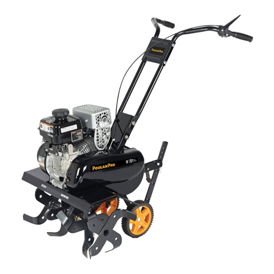
Poulan Pro HDF900 Operator's Manual
Front tine tiller
Hide thumbs
Also See for HDF900:
- Operator's manual (36 pages) ,
- Repair parts manual (8 pages) ,
- Operator's manual (40 pages)
Table of Contents
Advertisement
Quick Links
Download this manual
See also:
Repair Parts Manual
IMPORTANT MANUAL
OPERATOR'S MANUAL
MODEL:
HDF900
FRONT TINE TILLER
ALWAYS WEAR EYE PROTECTION DURING OPERATION
Visit our website: www.poulan-pro.com
427896 03.23.09 CL
Do Not Throw Away
WARNING:
Read this Man u al and follow all
Warnings and Safety Instructions.
Fail ure to do so can re sult in seri-
ous in ju ry.
Printed in U.S.A.
Advertisement
Table of Contents

Related Manuals for Poulan Pro HDF900


Summary of Contents for Poulan Pro HDF900
- Page 1 IMPORTANT MANUAL OPERATOR'S MANUAL MODEL: HDF900 FRONT TINE TILLER ALWAYS WEAR EYE PROTECTION DURING OPERATION Visit our website: www.poulan-pro.com 427896 03.23.09 CL Do Not Throw Away WARNING: Read this Man u al and follow all Warnings and Safety Instructions. Fail ure to do so can re sult in seri- ous in ju ry.
-
Page 2: Safety Rules
Allow the engine to cool before storing in any enclosure. • Always refer to the operator’s guide instructions for im por tant details if the tiller is to be stored for an ex- tended period. - IMPORTANT - CAUTIONS, IMPORTANTS, AND NOTES ARE A MEANS OF ATTRACTING ATTENTION TO IMPORTANT OR CRIT I CAL IN FOR MA TION IN THIS MANUAL. -
Page 3: Table Of Contents
We have com pe tent, well-trained tech ni cians and the proper tools to service or repair this unit. Please read and retain this manual. The in struc tions will enable you to assemble and main tain your tiller prop erly. Always observe the “SAFETY RULES”. TABLE OF CONTENTS SAFETY RULES ... -
Page 4: Assembly
Your new tiller has been assembled at the factory with exception of those parts left unassembled for shipping purposes. To ensure safe and proper operation of your tiller all parts and hardware you assemble must be tightened securely. Use the correct tools as necessary to insure proper tightness. - Page 5 (1" long) hex bolt is assembled in lower hole of handle. Repeat for opposite side. Tight en all hard- ware se cure ly. • Cut cable ties securing tiller to skid and remove tiller from skid. • Remove screws securing depth stake to skid and dis- card the screws.
-
Page 6: Operation
Compare the illustrations with your tiller to familiarize yourself with the location of various controls and adjustments. Save this manual for future reference. These symbols may appear on your Tiller or in literature supplied with the product. Learn and understand their mean- ing. -
Page 7: Tine Operation
The operation of any tiller can result in foreign objects thrown into the eyes, which can result in severe eye damage. Always wear safety glasses or eye shields before starting your tiller and while tilling. We recommend a wide vision safety mask for over spectacles or standard safety glasses. - Page 8 4 of this manual. All oil must meet A.P .I. Service Classification SG-SL. 4. Tilt tiller back on its wheels and then re-level. 5. With engine level, refill to point of over flow ing if nec- es sary. Re place oil filler plug.
-
Page 9: Operation
To slow down the tiller, press down on handles. If you are straining or tiller is shaking, the wheels and depth stake are not set properly in the soil being tilled. The proper setting of the wheels and depth stake is through trial and error and depends upon the soil con di tion. -
Page 10: Maintenance Schedule
GENERAL RECOMMENDATIONS The warranty on this tiller does not cover items that have been subjected to operator abuse or negligence. To receive full value from the warranty, the operator must main tain tiller as instructed in this manual. Some adjustments will need to be made periodically to properly maintain your tiller. - Page 11 Change the oil after every 25 hours of operation or at least once a year if the tiller is not used for 25 hours in one year. Check the crankcase oil level before starting the engine and after each five (5) hours of continuous use.
- Page 12 Wa ter in en gine will short en the useful life of your tiller. •...
-
Page 13: Service & Adjustments
TO ADJUST HANDLE HEIGHT (See Fig. 15) Factory assembly has provided lowest handle height. Se lect handle height best suited for your tilling conditions. Handle height will be different when tiller digs into soil. • If a higher handle height is desired, loosen the four nuts securing handle panel to engine brackets. -
Page 14: Service And Adjustments
SERVICE AND ADJUSTMENTS ENGINE TO AD JUST CARBURETOR The carburetor has been preset at the factory and ad just ment should not be necessary. However, engine per for mance can be affected by dif fer enc es in fuel, tem per a ture, al ti tude or load. -
Page 15: Service & Adjustments
SERVICE AND ADJUSTMENTS TO REPLACE V-BELT (See Fig. 21) Replace V-belt if it has stretched considerably or if it has cracks or frayed edges. Belt guard must be removed to service belt. See “TO RE- MOVE BELT GUARD” in this section of manual. BELT REMOVAL •... -
Page 16: Storage
Immediately prepare your tiller for storage at the end of the season or if the unit will not be used for 30 days or more. WARNING: Never store the tiller with gasoline in the tank inside a build ing where fumes may reach an open flame or spark. -
Page 17: Troubleshooting
Ground too dry and hard. difficult handling Wheels and depth stake incorrectly adjusted. Soil balls up or clumps Ground too wet. Engine runs but tiller Tine control is not engaged. won’t move V-belt not correctly adjusted. V-belt is off pulley (s). - Page 18 SERVICE NOTES...
-
Page 19: Warranty
6. In the event you have a claim under this Warranty, you must return the product to an authorized service deal- Should you have any unanswered questions concerning this Warranty, please contact: Poulan Pro Customer Service Dept. 1030 Stevens Creek Road... -
Page 20: Parts And Service
Model Number/Manufacturer's I.D. Number b. Description of part. For Technical Assistance: call 1-800-829-5886 For a Parts Manual, go to our website: www.poulan-pro.com/support.asp NOTE: HOP provides parts and service through its au thor ized dis tribu tors and dealers; there fore, all requests for parts and service should be directed to your local dealer(s). - Page 21 à mises votre S.V.P contactez Manuel, caractéristiques produits. philosophie proche. plus pièces mande toute conséquent l’intermédiaire www.poulan-pro.com/support.asp 1-800-849-1297 appelez autorisé: d’effectuer machine votre durabilité pour Comme stricts. dards stan CHANGE concernant l’assistance tions dans décrites celles différentes complète gamme nence agréé...
- Page 22 énoncées durée conséquents dommages GARANTIES POUR PRÉCISÉES INCIDENTEL DOMMAGE votre d’achat date série, Ontario Mississauga, Drive Ordan 7075 POULAN Canada: plaît vous s’il garantie, cette concernant retourner veuillez-vous garantie, cette garantie. normal, l’usage dents, adaptateurs livraison lors avariés installés...
- Page 23 D'ENTRETIEN REMARQUES...
- Page 24 d’étrangleur. commande réglage Vérifi profond. moins soit sarclage sorte profondeur montants Réglez courroie Inspectez courroie Inspectez/réglez dents commande Enclenchez favorables. plus soient conditions Attendez profondeur. montants roues Réglez favorables. plus soient conditions attendez Mouillez nettoyez-le. silencieux Déposez silencieux. à ltre fi...
- Page 25 CHAUDS. D'ÉCHAPPEMENT CIRCUIT MOTOBINEUSE JAMAIS COUVREZ l'unité. rouiller à fera formation permet d’air circulation tique plas plastique. couverture ble. méa couverture avec motobineuse saleté. poussière protegér possible, l’intérieur, à motobineuse caus l’essence dans saleté et/ou rouiller. à commence s’il d’essence l’autre.
- Page 26 TRANSMISSION POULIE COURROIE PROTECTEUR manuel. FRAISES” L'UTILISATION “VERIFICATION FRAISES L'UTILISATION galet-tendeur. poulie qu’elle guides-courroie, tous deux intérieure rainure dans trouve Assurez-vous transmission. poulie moteur poulie trapézoïdale courroie COURROIE RÉGLAGES Fig. GALET-TENDEUR POULIE PÉZOÏDALE TRA- COURROIE REMPLACER poulie section cette dans Voir •...
- Page 27 Fig. Courroie Protecteur à serrés soient écrous tous boulon tête sous trouve courroie fond située l’encoche Assurez-vous étapes inversant courroie protecteur motobineuse. loin courroie courroie. protecteur côté COUR- PROTECTEUR Fig. FRAISE CÂBLE CORPS RÉGLAGES quand “ARRÊT” (“ON”) encore tirez com- observez fond.
- Page 28 NECESSAIRES. REPARATIONS OUTILS QUALIFIES TECHNICIENS DOMICILE. VOTRE PROCHE PLUS ADRESSEZ-VOUS NECESSAIRE, REGLAGE QU’UN PENSEZ VOUS PEUT ACTION CETTE VITESSE. CETTE UTILISE. ETRE DOIT MOTEUR LAQUELLE MAXIMUM VITESSE DETERMINE ’EQUIPEMENT CONSTRUCTEUR REGULATEUR TOUCHEZ proche. plus autorisé d'entretien avec quez nécessaire, réglage carburant température, d’altitude,...
- Page 29 d’auto. cire avec peintes surfaces etc. l’huile, peintes surfaces roues propreté toutes etc. finition, roues, motobineuse. moteur niveau d’eau ’entrée d’eau. toute contre protégés sont carburateur silencieux transmission, machine nettoyer afin etc.) d’arrosage, l’eau utiliser mieux serait transmission moteur motobineuse réparée.
- Page 30 Fig. À Filtre Couvercle Prefiltre Mousse À Filtre Cartouche SÉCHER NETTOYER POUR METTEZ CELLE-CI. PROVOQUER RISQUENT CARTOUCHE. POUR UTILISÉS ÊTRE DOIVENT TELS PÉTROLE, SOLVANTS vis. fond à Serrez couvercle. remettez cartouche. remplacez avariée, plate. surface légèrement frappant dans entrer débris saletés Faites air.
- Page 31 MOTEUR. ENTRETIEN SECTION 10W30 MOTEUR FRAISES COMMANDE LUBRIFICATION À RÉFÉREZ-VOUS MOTEUR HUILE portez GALET-TENDEUR BRAS fonctionner air/essence courroies nettoyez saison. Réglages pour périodiquement manuel. doit teur part éléments GÉNÉRALES TABLEAU ENTRETIEN LUBRIFICATION” lubrifiée. bien motobineuse votre LUBRIFICATION fixation. systèmes solidité fraises.
- Page 32 Fig. sent pous n’y herbes mauvaises terre laisser herbes mauvaises permettra vitesse à rangs jauge. ressort tenue soit jauge avant penchant Commencez jauge d’utiliser probablement nécessaire pouces à entre situe binage l’humidité. conservation à contribuera couche travailler plus, d’aliments. priver empêcher herbes pour...
- Page 33 démarrer. d'action moins requiert chaud moteur moteur. réchauffement pendant opposée graduellement déplacez moteur, démarrer (mar- » « position à placé été l’étrangleur démarre. lanceur poignée Tirez mi-course. dé- pas, démarre mais pétarade, moteur rétractant. démarreur heurter lanceur laissez lanceur. poignée point.) à...
- Page 34 désiré. l’endroit jusqu’à motobineuse sol. fraises soulever pour poignées jauge. ressort maintenue jusqu’à devant vers profondeur réservoir. l’essence d’allumage. bougie Débranchez ter. trans soulever avant moteur refroidir Laissez ATTENTION: TRANSPORTER Fig. ROUE JAUGE RESSORT PROFONDEUR JAUGE CHAPE ’AXE CHEVEUX À ÉPINGLE COLLIER normal.
- Page 35 carburateur. carburant réservoir ouvre carburant soupape CARBURANT moteur. démarrer permet DÉMARRAGE bêche. profondeur vitesse commande PROFONDEUR Institute”. Standards National FRAISES FRAISES DÉFLECTEUR MOTEUR COMMUTATEUR CARBURANT ROBINET HUILE ESSENCE ÊTRANGLEUR ARRÊT MARCHE comprenez Apprenez produit. réglages. différents commandes D’UTILISER AVANT SÉCURITÉ moteur entre passage...
- Page 36 manuel.) Révision section dans DENT” TION “VE à (Référez-vous dents. vérifiez motobineuse, votre usage DENTS manuel.) Réglages dans DENTS” “DISPOSITION demandes pour réglée Réglages Révision tion TEUR “HAU à (Référez-vous l’opérateur. position à réglée être peut poignée POIGNÉE Fig. NAUX HEXA ÉCROUS BLOCAGE,...
- Page 37 5/16-18 Écrous Fig. ’OPÉRATEUR POSITION DROITE DEVANT outils. bons Utilisez fond. à serrées correcte utilisation d'une s'assurer Pour 5/16 Frein Rondelles Rondelles PIÈCES CONTENU l'utilisateur GAUCHE sions MONTAGE être doivent assemblez vous ferrures l'expédition. pièces certaines MONTAGE 1-1/4 5/16-18 Boulons 5/16-18 Boulons guidon.
- Page 38 DÉPANNAGE 13-15 RÉGLAGES 10-12 PIÉCES. FigURE PIÈCE NUMÉRO PARE-ÉTINCELLES. PRÉS PLUS AUTORISÉ D’ENTRETIEN FONCTIONNEMENT MAINTENU UTILISÉ, PARE-ÉTINCELLES LOCALES LOIS EXIGENCES PARE-ÉTINCELLES D’UN MUNI SYSTÈME HERBE D’ARBRISSEAUX, COUVERT TERRAIN D’UN PRÈS ÊTRE DEVRAIT INTERNE MOTEUR D’UN MUNIE MACHINE prié manuel “Entretien" sections dans instructions...
- Page 39 réparations. ments ajus port, trans tion, lors d’al bougie avec trer puis qu’il sez-le accidentels, pré pour d’allumage toujours Débranchez ATTENTION: JEU. TÉ SÉ VOTRE PRUDENT TION signifie sécurité. importants points signale ’EXÉCUTION ’INTÉGRATION ATTENTION VOTRE ATTIRE ’ÉQUIPEMENT À DOMMAGES ATTENTION VOTRE ATTIRE...
- Page 40 AVERTISSEMENT: JETEZ www.poulan-pro.com l’utilisation. lors sécurité aver résulter sures bles struc tous suivez Lisez OPÉRATEUR 03.23.09 web: site notre Visitez lunettes toujours Portez AVANT FRAISE MOTOBINEUSE HDF900 MODÈLE: MANUEL IMPORTANT MANUEL 427896 À...