Table of Contents
Advertisement
Quick Links
IMPORTANT MANUAL
OPERATOR'S MANUAL
MODEL:
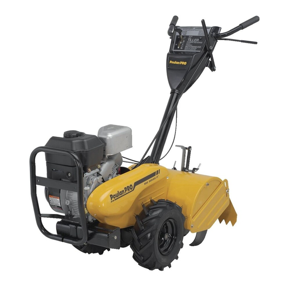
RT900
REAR TINE TILLER
ALWAYS WEAR EYE PROTECTION DURING OPERATION
Visit our website: www.poulan-pro.com
432121
Do Not Throw Away
WARNING:
Read this Man u al and follow all Warnings
and Safety Instructions. Fail ure to do so
can re sult in serious in ju ry.
12.21.09 TH
Printed in U.S.A.
Advertisement
Table of Contents

Related Manuals for Poulan Pro 432121


Summary of Contents for Poulan Pro 432121
- Page 1 OPERATOR'S MANUAL MODEL: RT900 REAR TINE TILLER ALWAYS WEAR EYE PROTECTION DURING OPERATION Visit our website: www.poulan-pro.com 432121 Do Not Throw Away WARNING: Read this Man u al and follow all Warnings and Safety Instructions. Fail ure to do so can re sult in serious in ju ry.
-
Page 2: Safety Rules
Allow the engine to cool before storing in any enclosure. • Always refer to the operator’s guide instructions for im por tant details if the tiller is to be stored for an ex- tended period. - IMPORTANT - CAUTIONS, IMPORTANTS, AND NOTES ARE A MEANS OF ATTRACTING ATTENTION TO IMPORTANT OR CRIT I CAL IN FOR MA TION IN THIS MANUAL. -
Page 3: Table Of Contents
We have com pe tent, well-trained tech ni cians and the proper tools to service or repair this unit. Please read and retain this manual. The in struc tions will enable you to assemble and main tain your tiller prop erly. Always observe the “SAFETY RULES”. TABLE OF CONTENTS SAFETY RULES ...2... -
Page 4: Assembly
Your new tiller has been assembled at the factory with exception of those parts left unassembled for shipping purposes. To ensure safe and proper operation of your tiller all parts and hardware you assemble must be tightened securely. Use the correct tools as necessary to insure proper tightness. - Page 5 Slide handle assembly into position. • Rotate handle assembly down. Insert rear carriage bolt first, with bolt head on L.H. side of tiller and loosely assemble locknut (See Fig. 5). • Insert pivot bolt in front part of plate and tighten.
- Page 6 • Tilt tiller forward by lifting handle. Separate cardboard cover from leveling shield. • Rotate tiller handle to the right and pull tiller out of carton. CHECK TIRE PRESSURE The tires on your unit were overinflated at the factory for shipping purposes.
-
Page 7: Operation
KNOW YOUR TILLER READ THIS OWNER'S MANUAL AND SAFETY RULES BEFORE OPERATING YOUR TILLER. Compare the illustrations with your tiller to familiarize yourself with the location of various controls and adjustments. Save this manual for future reference. These symbols may appear on your Tiller or in literature supplied with the product. Learn and understand their meaning. - Page 8 The operation of any tiller can result in foreign objects thrown into the eyes, which can result in severe eye damage. Always wear safety glasses or eye shields before starting your tiller and while tilling. We recommend a wide vision safety mask for over spectacles or standard safety glasses.
- Page 9 • Release the depth stake pin. Move the depth stake down to the top hole for transporting the tiller. Place depth stake pin in hole of depth stake to lock in posi- tion. This prevents tines from scuffing the ground.
-
Page 10: Operation
Loose, unpacked soil helps root growth. Best tilling depth is 4" to 6" (10-15 cm). A tiller will also clear the soil of unwanted vege ta tion. The de com po si tion of this vegetable mat ter enriches the soil. -
Page 11: Maintenance Schedule
2 - Service more often when operating in dirty or dusty conditions. GENERAL RECOMMENDATIONS The warranty on this tiller does not cover items that have been subjected to operator abuse or negligence. To receive full value from the warranty, the operator must main tain tiller as instructed in this manual. -
Page 12: Maintenance
Change the oil after every 25 hours of operation or at least once a year if the tiller is not used for 25 hours in one year. Check the crankcase oil level before starting the engine and after each five (5) hours of continuous use. - Page 13 Wa ter in en gine will short en the useful life of your tiller. •...
-
Page 14: Service & Adjustments
Fig. 21 TO REMOVE BELT GUARD (See Fig. 22) NOTE: For ease of removal, remove hairpin clip and clevis pin from left wheel. Pull wheel out from tiller about 1 inch. • Remove two (2) screws from side of belt guard. -
Page 15: Service And Adjustments
SERVICE AND ADJUSTMENTS TO REPLACE GROUND DRIVE BELT (See Fig. 23) • Remove belt guard (See “TO REMOVE BELT GUARD” in this section of this manual). • Remove old belt by slipping off engine pulley first then remove from transmission pulley. •... - Page 16 A badly worn tine causes your tiller to work harder and dig more shallow. Most important, worn tines cannot chop and shred organic matter as effectively nor bury it as deeply as good tines.
-
Page 17: Service & Adjustments
SERVICE AND ADJUSTMENTS ENGINE TO AD JUST CARBURETOR The carburetor has been preset at the factory and ad just ment should not be necessary. However, engine per for mance can be affected by dif fer enc es in fuel, tem per a ture, al ti tude or load. -
Page 18: Storage
Immediately prepare your tiller for storage at the end of the season or if the unit will not be used for 30 days or more. WARNING: Never store the tiller with gasoline in the tank inside a build ing where fumes may reach an open flame or spark. -
Page 19: Troubleshooting
1. Ground too dry and hard. difficult handling Soil balls up or clumps 1. Ground too wet. Engine runs but tiller 1. Drive control bar is not engaged. won’t move 2. V-belt not correctly adjusted. 3. V-belt is off pulley(s). -
Page 20: Warranty
The Manufacturer warrants to the original consumer purchaser that this product as manufactured is free from defects in materials and work man ship. For a period of one (1) years from date of purchase by the original consumer purchaser, we will repair or replace, at our option, without charge for parts or labor incurred in replacing parts, any part which we find to be defective due to materials or workmanship. - Page 21 SERVICE NOTES...
-
Page 22: Parts And Service
For a Parts Manual, go to our website: www.poulan-pro.com/support.asp NOTE: Poulan Pro provides parts and service through its au thor ized dis tribu tors and dealers; there fore, all requests for parts and service should be directed to your local dealer(s). The phi loso phy of HOP is to con tinu ally improve all of its prod ucts. - Page 23 à mises concernant l’assistance con- Manuel, dans décrites celles car- produits. complète proche. plus agréé distributeur mande toute conséquent l’entretien www.poulan-pro.com/support.asp 1-800-849-1297 appelez autorisé: d’effectuer machine votre durabilité pour Comme stricts. dards stan CHANGE tions pour différentes sont outil votre...
- Page 24 D’ENTRETIEN REMARQUES...
-
Page 25: Garantie
1975. droits donne vous garantie Cette vous. conséquent, implicite garantie Certaines FABRICANT. EXPLICITES IMPLICITE GARANTIE TOUTE concession- l’adresse ainsi machine Ontario contactez: concessionnaire à machine votre standard, visserie normaux, réglages normal. usage livraison modifiés, été produits ins- conformément entretenus quatre-vingt- à... -
Page 26: Dépannage De Guide
cisaillement. boulon(s) le(s) carburateur. gaz. commande réglage profond. moins pour roues profondeur tasseau commande. barre trapézoïdale courroie Vérifiez/réglez trapézoïdale. courroie favorables. plus conditions d’être favorables. plus d’être attendez légèrement riche. plus position à carburateur silencieux. nettoyez autour d’air, tamis cyl., ailettes d’air. -
Page 27: Entreposage
SONT D'ÉCHAPPEMENT CIRCUIT MOTOBINEUSE JAMAIS COUVREZ l'unité. tion formation permet d’air obs- tique plas plastique. couverture ble. méa couverture avec motobineuse saleté. poussière protegér cou- possible, l’intérieur, à motobineuse caus l’essence dans saleté et/ou rouiller. à commence s’il d’essence l’autre. à... -
Page 28: Réglages Et Révision
REPARATIONS QUALIFIES PROCHE NECESSAIRE, QU’UN CETTE ETRE MAXIMUM centre/département réglage d’altitude, être être RÉGLAGES POUR APPROPRIES TECHNICIENS DOMICILE.QUI PLUS AGREE ’AGENT MAXIMUM VITESSE PENSEZ VOUS DANGEREUSE. VITESSE. CETTE JAMAIS DEPASSEZ DOIT MOTEUR LAQUELLE VITESSE DETERMINE ’EQUIPEMENT CONSTRUCTEUR REGULATEUR TOUCHEZ proche. plus avec quez... - Page 29 CHEVEUX À ÉPINGLE COLLIER CHANT TRAN- BORD FRAISE ROTATION Fig. FRAI tine_2 TRANSMISSION haut. tourneront aiguisés fraise bords illustré comme montées être devraient cas. suivant redresser, convient cm), pouces 3-1/2 entre l’écart transmission. côté fraises particulier gauchissement, l’acuité, point fraises fonctionnement, machine cette...
- Page 30 5/8" SION PLUS SION MOINS D’ENTRAÎNEMENT COMMANDE CÂBLE CÂBLE COLLIER câble. serrage collier engagée. barre pendant allongement d’un l’obtention jusqu’à tension arrière tension moins pour câble d’entraînement. fixe câble serrage collier être peut tension Cette “ENGAGED”. d’entraînement commande barre allongement approximativement traction ressort...
- Page 31 Fig. CHAPE CHEVEUX À ÉPINGLE COLLIER ROUE) RIÈRE DER- (SITUÉ RONDELLE ÉCROU RONDELLE BORGNE ÉCROU procédé rinversant courroie protecteur motobineuse. loin courroie pneu.) derrière teur fond rondelle hexagonal courroie. protecteur côté distance jusqu’à motobineuse gauche. roue chape l’axe collier enlevez l’enlèvement, faciliter COUR-...
-
Page 32: Entretien
d’auto. cire avec peintes surfaces etc. l’huile, peintes surfaces roues propreté toutes etc. finition, roues, votre durée réduit moteur ’entrée d’eau. possible pénétration sont carburateur à filtre transmission, près garniture nettoyer afin etc.) d’arrosage, (tuyau utiliser mieux serait chauds. transmis- moteur motobineuse graisse... - Page 33 Fig. À FILTRE CARTOUCHE sécher nettoyer pour comprimé N’uti che. mettez cartouche. détérioration risquent cartouche. toyer utilisés être doivent kérosène, tels pétrole, solvants vis. fond à Serrez couvercle. remettez cartouche. remplacez avariée, plate. surface légèrement frappant dans entrer débris saletés Faites air.
- Page 34 MOTEUR. ENTRETIEN SECTION 10W30 ROUE MOYEU NIVELLEMENT DÉFLECTEUR CHARNIÈRES PROFONDEUR JAUGE GOUPILLE VITESSE BOÎTE DROIT CÔTÉ GRAISSE RACCORD LUBRIFICATION élevée. ambiante D’ENTRETIEN DATES portez GRAISSE À RÉFÉREZ-VOUS MOTEUR HUILE GALET-TENDEUR BRAS mieux air/ mélange courroies nettoyez fois Réglages MOTEUR périodiquement garantie égligence TABLEAU...
- Page 35 manuel. Pièces section dans montrés ceux remplacez-les cassent, cisaillement à surviennent internes dommaqes pour conçus sont cisaillement boulons surchargée motobineuse manuel). Révision section dans dents” (Voyez cisaillement boulons avec fixés sont motobineuse votre dents DENTS CISAILLEMENT Fig. 15). Fig. (Voir plus poussent herbes...
- Page 36 moteur. déplace pour (recul) démarrage poignée nécessaire sera d'essence, plus fois première pour moteur (OFF). d'arrêt position d'entraî- commande barre moteur, démarrage Lors MOTEUR DÉMARRER causés. nents sinon ré- dans carburateur moteur produits jamais N’uti autres pour l’en tez-vous saison des.
-
Page 37: Utilisation
Fig. “A” ROUILLA- POSITION RELÂCHÉE POSITION FON- JAUGE GOUPILLE AUTRE À VITESSE CHANGEMENT DÉPLACER AVANT D’ENTRAÎNEMENT BARRE TOUJOURS RELÂCHEZ désirée. position à déplacée commande biner, Pour profond. plus (“FAST”) rapide position à commande dents labourage. commencer contre d’entraînement commande labourage. à... - Page 38 dé- permet (RECUL) DÉMARRAGE trans- l’engrenage position CHANGEMENT LEVIER intermédiaires. transmissions permet VITESSE CHANGEMENT bêche. motobineuse profondeur commande PROFONDEUR Institute”. Standards National “American (RECUL) DÉMARRAGE POIGNÉE COMMANDE STARTER COMMANDE HUILE ESSENCE ÊTRANGLEUR ARRÊT MARCHE com- Apprenez produit. avec différents commandes différentes D’UTILISER AVANT...
-
Page 39: Montage
manuel.) section HAUTEUR “REGLER section à venir pour réglée être peut poignée POIGNEE PSI). kg/cm à pneu pression labourage. résultats pour pneus deux pour même l’expédition. pour l’usine à surgonflés PNEU PRESSION carton. enlever droite à motobineuse déflecteur carton couvercle poi- levant devant... - Page 40 Fig. FREIN ÉCROU PIVOT À BOULON POIGNÉE VERROU LEVIER PLATE RONDELLE basse. plus position l’ensemble laissant carton motobineuse facile plus sera montre. d’une aiguilles tournant poignée verrou levier basse plus position à poignée l’intérieur (à poignée socle l’encoche vers dents (les mince plus...
- Page 41 pince cheveux à épingle Collier 3/8-16 frein Écrou Fig. ’OPÉRATEUR POSITION DROITE DEVANT serrées être doivent assemblez vous d'une s'assurer Pour l'expédition. & cisaillement Boulons poignée verrou Levier Cat. 3/8-16 chariot Boulon PIÈCES CONTENU l'utilisa- GAUCHE MONTAGE ferrures pièces toutes pièces certaines sauf...
- Page 42 DÉPANNAGE 14-17 RÉGLAGES 11-13 PARE-ÉTINCELLES. PROCHE PLUS AUTORISÉ D’ENTRETIEN FONCTIONNEMENT MAINTENU UTILISÉ, PARE-ÉTINCELLES LOCALES LOIS EXIGENCES PARE-ÉTINCELLES D’UN MUNI SYSTÈME HERBES ARBRES, COUVERT TERRAIN ÊTRE DEVRAIT INTERNE MOTEUR D’UN MUNI MACHINE prié manuel Entretien sections dans instructions motobineuse. d’uti- soin, d’entretien, habituel programme...
-
Page 43: Sécurité De Règles
reproducteur. système d’autre naissance, l’infirmité vent quantités, certaines dans duits contiennent produit d’échap- Californie AVERTISSEMENT réparations. ments ajus port, trans tion, lors d’al bougie avec contact puis qu’il çon telle sez-le acci- dé pré pour toujours Débranchez TÉ SÉ VOTRE PRUDENT !!!, TION... - Page 44 AVERTISSEMENT: JETEZ www.poulan-pro.com l’utilisation. lors sécurité struc vous sures struc suivez Lisez PROPRIÉTAIRE 432121 web: site notre Visitez lunettes toujours Portez MOTOBINEUSE RT900 MODÈLE: MANUEL IMPORTANT MANUEL...