Table of Contents
Advertisement
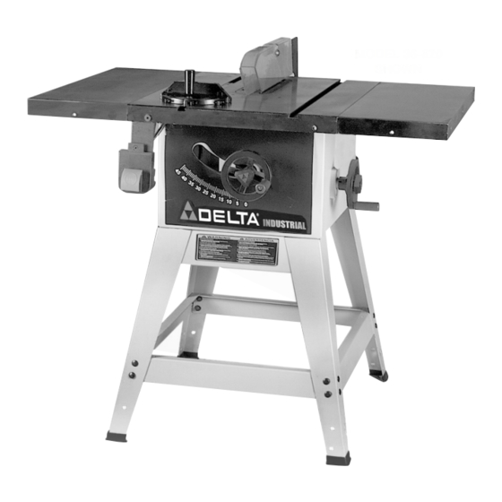
10" Contractor's Saw
(Models 36-649, 36-675, 36-678, 36-679)
MODEL 36-679
SHOWN
PART NO. 912857 - 8-23-04
Copyright © 2004 Delta Machinery
To learn more about DELTA MACHINERY
visit our website at: www.deltamachinery.com.
For Parts, Service, Warranty or other Assistance,
1-800-223-7278 (
1-800-463-3582).
please call
In Canada call
Advertisement
Table of Contents

Related Manuals for Delta 36-649


Summary of Contents for Delta 36-649
- Page 1 10" Contractor’s Saw (Models 36-649, 36-675, 36-678, 36-679) MODEL 36-679 SHOWN PART NO. 912857 - 8-23-04 Copyright © 2004 Delta Machinery To learn more about DELTA MACHINERY visit our website at: www.deltamachinery.com. For Parts, Service, Warranty or other Assistance, 1-800-223-7278 ( 1-800-463-3582).
-
Page 2: Table Of Contents
IMPORTANT SAFETY INSTRUCTIONS ............2 SAFETY GUIDELINES . -
Page 3: Safety Guidelines
SAFETY GUIDELINES - DEFINITIONS It is important for you to read and understand this manual. The information it contains relates to protecting YOUR SAFETY and PREVENTING PROBLEMS. The symbols below are used to help you recognize this information. Indicates an imminently hazardous situation which, if not avoided, will result in death or serious injury. Indicates a potentially hazardous situation which, if not avoided, could result in death or serious injury. -
Page 4: General Safety Rules
GENERAL SAFETY RULES READ AND UNDERSTAND ALL WARNINGS AND OPERATING INSTRUCTIONS BEFORE USING THIS EQUIPMENT. Failure to follow all instructions listed below, may result in electric shock, fire, and/or serious personal injury or property damage. 1. FOR YOUR OWN SAFETY, READ THE INSTRUCTION MANUAL BEFORE OPERATING THE MACHINE. -
Page 5: Additional Specific Safety Rules
15. NEVER have any part of your body in line with the path of the saw blade. 16. NEVER REACH AROUND or over the saw blade. 17. NEVER attempt to free a stalled saw blade without first turning the machine “OFF”. 18. PROPERLY SUPPORT LONG OR WIDE workpieces. -
Page 6: Power Connections
POWER CONNECTIONS A separate electrical circuit should be used for your machines. This circuit should not be less than #12 wire and should be protected with a 20 Amp time lag fuse. If an extension cord is used, use only 3-wire extension cords which have 3- prong grounding type plugs and matching receptacle which will accept the machine’s plug. -
Page 7: Extension Cords
3. 240 VOLT SINGLE PHASE OPERATION: The motor supplied with your saw is a dual voltage, 120/240 volt motor. If it is desired to operate your saw at 240 volts, single phase, it is necessary to reconnect the motor leads in the motor junction box by following the in-structions given on the motor nameplate. -
Page 8: Functional Description
FUNCTIONAL DESCRIPTION FOREWORD Delta Models 36-649, 36-675, 36-678 and 36-679 are 10" contractor saws. The saws have a powerful 1½ HP induction motor which can handle tough cutting operations. A RIP FENCE ASSEMBLY IS NOT PACKAGED WITH THE PRODUCT. YOU MUST INSTALL AND USE A RIP FENCE SYSTEM FOR RIPPING OPERATIONS. -
Page 9: Extension Wings
EXTENSION WINGS MODEL 36-649 2 SHEET METAL EXTENSION WINGS STAND PARTS 1. Leg (4) 2. Bracket 24" Long (2) 3. Bracket 21" Long (2) 4. Top Bracket (1) 5. Plastic Foot (4) MODEL 36-678 1 CAST IRON EXTENSION WING Fig. 3 Fig. -
Page 10: Assembly
HARDWARE 1. 7/16-20x3/4" Hex Head Screw (6) 2. 3/8-16x1½" Flat Head Screw (1) 3. 5/16-18x3/4" Carriage Head Screw (4) 4. 5/16-18x5/8" Hex Head Screw (8) 5. 5/16-18x5/8" Carriage Head Screw (17) 6. 1/4-20x1½" Hex Head Screw (1) 7. 1/4-20x3/4" Hex Head Screw (2) 8. - Page 11 CARDBOARD, CARPET ETC. NOTE: Make certain the shorter stand brackets (D) Fig. 8, are at the front and rear of the saw as shown. 2. Align the eight holes in the bottom of the saw cabinet with the eight holes in stand legs. Place a 5/16"...
- Page 12 CAREFULLY TURN THE SAW AND STAND UPRIGHT AS SHOWN IN FIG. 10. Carefully push down on the top of the saw until the stand legs adapt to the floor surface. Make sure the table top is level and firmly tighten all stand mounting hardware.
- Page 13 2. Insert switch cord (A) Fig. 14, and motor cord (B) into clamps (D) and loosely fasten both cords (A) and (B) Fig. 15, to the saw cabinet by turning screws (E) Fig. 14, clockwise. NOTE: Cords will be adjusted later. Place switch on top of the saw table at this time.
- Page 14 (A) until pins (X) are engaged in holes (D) Fig. 17, of motor mounting plate (A). 6. Fig. 19, illustrates the motor and motor mounting plate assembled to the rear of the saw. Fig. 16 Fig. 17 Fig. 18...
- Page 15 MOTOR PULLEY, PULLEY GUARD, AND DRIVE BELT DISCONNECT MACHINE FROM POWER SOURCE. 2. Remove the motor shaft key that is taped to the motor. 3. Insert key (A) Fig. 20, in the keyway on the motor shaft. Assemble motor pulley (B) on motor shaft as shown, with the hub of the pulley out.
- Page 16 IMMEDIATELY AFTER ASSEMBLING THE BELT, RAISE THE SAW BLADE TO ITS MAXIMUM HEIGHT AND TILT THE SAW BLADE TO 45 DEGREES. USING A STRAIGHT EDGE (L) FIG. 25, CHECK TO SEE IF THE MOTOR END (J) FIG. 25, IS BELOW THE TOP OF THE TABLE SURFACE (K).
- Page 17 Repeat this process for the remaining hole. Do not completely tighten the two screws (B) at this time. 3. Raise saw arbor to its highest position. 4. Remove screw and large washer (C) Fig. 30, from the inside splitter mounting bracket.
- Page 18 (L) of splitter (G); the blade guard will stay in this position. 10. With the blade guard (L) Fig. 36, in the raised position, assemble the saw blade (K) on the saw arbor with two arbor wrenches supplied. Fig. 33 Fig.
- Page 19 11. Using a straight edge, check to see if the saw blade is aligned with the rear of the splitter (G), as shown in Fig. 37. If alignment is necessary, loosen the screws (A) Fig. 37, align splitter (G) with the saw blade, and tighten two screws (A).
-
Page 20: Operation
Fig. 41 STARTING AND STOPPING SAW 1. The on/off switch is located underneath the switch shield (A) Fig. 41. To turn the saw “ON”, move switch trigger (B) to the up position. 2. To turn the saw “OFF”, push down on switch shield (A) Fig. 42. - Page 21 RAISING AND LOWERING BLADE To raise the saw blade, loosen lock knob (A) Fig. 44, and turn the blade raising handwheel (B) clockwise. When the blade is at the desired height, tighten lock knob (A). To lower the blade, loosen lock knob (A) Fig. 44, and turn the handwheel (B) counterclockwise.
- Page 22 MITER GAGE OPERATION AND ADJUSTMENT Insert the miter gage bar (B) Fig. 47, into the miter gage slot. Insert the metal stud on the bottom of the miter gage body (C) Fig. 47, into the non tapped hole in the miter gage bar.
-
Page 23: Changing The Saw Blade
POWER SOURCE. 2. NOTE: Two 7/8" wrenches are supplied with the saw for changing the saw blade: a box end wrench (A) Fig. 51, and open end wrench (B). 3. Remove table insert (C) Fig. 68, and raise saw blade to its maximum height. - Page 24 Start the cut slowly and hold the work firmly against the miter gage and the table. One of the rules in running a saw is that you never hang onto or touch a free piece of work. Hold the supported piece, not the free piece that is cut off.
- Page 25 1. Start the motor and advance the work holding it down and against the fence. Never stand in the line of the saw cut when ripping. When the rip width is 6 inches or wider, hold the work with both hands and push it along the fence and into the saw blade (Fig.
- Page 26 1 inch facing. 3. Position the wood-facing over the cutterhead with the cutterhead below the surface of the table. Turn the saw on and raise the cutterhead. The cutterhead will cut its own groove in the wood-facing. Fig. 61 shows a typical moulding operation.
- Page 27 2. Attach the dado head set (D) Fig. 64, to the saw arbor. NOTE: THE OUTSIDE ARBOR FLANGE CAN NOT BE USED WITH THE DADO HEAD SET, TIGHTEN THE ARBOR NUT AGAINST THE DADO HEAD SET BODY.
-
Page 28: Constructing A Featherboard
Further information on the safe and proper operation of table saws is available in the Delta “Getting the Most Out of Your Table Saw” How-To Book, Catalog No. 11-400. Additional Information on table saw safety, including a table saw safety video, is... -
Page 29: Troubleshooting
CONSTRUCTING A PUSH STICK When ripping work less than 4 inches wide, a push stick should be used to complete the feed and could easily be made from scrap material by following the pattern shown in Fig. 69. TROUBLESHOOTING For assistance with your machine, visit our website at www.deltamachinery.com for a list of service centers or call the DELTA Machinery help line at 1-800-223-7278 (In Canada call 1-800-463-3582). -
Page 30: Maintenance
All Delta Machines and accessories are manufactured to high quality standards and are serviced by a network • of Porter-Cable Delta Factory Service Centers and Delta Authorized Service Stations. To obtain additional information regarding your Delta quality product or to obtain parts, service, warranty assistance, or the location of the nearest service outlet, please call 1-800-223-7278 (In Canada call 1-800-463-3582). -
Page 31: Accessories
A complete line of accessories is available from your Delta Supplier, Porter-Cable • Delta Factory Service Centers, and Delta Authorized Service Stations. Please visit our Web Site for the name of your nearest supplier. Since accessories other than those offered by Delta have not been tested with this product, use of such accessories could be hazardous. - Page 32 Phone: (604) 420-0102 Fax: (604) 420-3522 The following are trademarks of PORTER-CABLE • DELTA (Las siguientes son marcas registradas de PORTER-CABLE • DELTA S.A.) (Les marques suivantes sont des marques de fabriquant de la PORTER-CABLE • DELTA): Auto-Set Contractor’s Saw II™, Delta ®...