Table of Contents
Advertisement
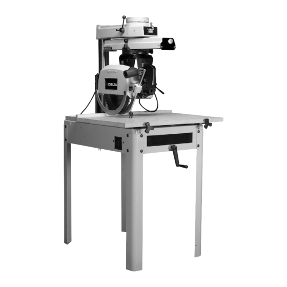
(Model 33-890, 33-895X, 33-891, 33-892)
Record this information for future reference.
SERIAL NO.______________________________
DATE OF PURCHASE ____________________
To learn more about DELTA MACHINERY
visit our website at: www.deltamachinery.com.
For Parts, Service, Warranty or other Assistance,
1-800-223-7278 (
please call
12" Radial Arm Saw
1-800-463-3582).
In Canada call
PART NO. 424-02-651-0025 - 03-18-05
Copyright © 2005 Delta Machinery
Advertisement
Table of Contents

Related Manuals for Delta 33-890


Summary of Contents for Delta 33-890
- Page 1 (Model 33-890, 33-895X, 33-891, 33-892) Record this information for future reference. SERIAL NO.______________________________ DATE OF PURCHASE ____________________ To learn more about DELTA MACHINERY visit our website at: www.deltamachinery.com. For Parts, Service, Warranty or other Assistance, 1-800-223-7278 ( please call 12" Radial Arm Saw PART NO.
-
Page 2: Table Of Contents
IMPORTANT SAFETY INSTRUCTIONS ............2 SAFETY GUIDELINES . -
Page 3: Safety Guidelines
SAFETY GUIDELINES - DEFINITIONS It is important for you to read and understand this manual. The information it contains relates to protecting YOUR SAFETY and PREVENTING PROBLEMS. The symbols below are used to help you recognize this information. Indicates an imminently hazardous situation which, if not avoided, will result in death or serious injury. Indicates a potentially hazardous situation which, if not avoided, could result in death or serious injury. -
Page 4: General Safety Rules
READ AND UNDERSTAND ALL WARNINGS AND OPERATING INSTRUCTIONS BEFORE USING THIS EQUIPMENT. Failure to follow all instructions listed below, may result in electric shock, fire, and/or serious personal injury or property damage. 1. FOR YOUR OWN SAFETY, READ THE INSTRUCTION MANUAL BEFORE OPERATING THE MACHINE. -
Page 5: Additional Specific Safety Rules
REMOVE CUT-OFF PIECES AND SCRAPS from the table before starting the saw. The vibration of the machine may cause them to move into the saw blade and be thrown out. After cutting, turn the SAVE THESE INSTRUCTIONS. -
Page 6: Power Connections
MOTOR SPECIFICATIONS Your machine either has a 230V, 60 HZ single phase motor (33-890, 33-895X and 33-891) or it has a 230V/460V 60 HZ three phase motor (33-892). Before connecting the machine to the power source, make sure the switch is off. -
Page 7: Extension Cords
EXTENSION CORDS Use proper extension cords. Make sure your extension cord is in good condition and is a 3-wire extension cord which has a 3-prong grounding type plug and matching receptacle which will accept the machine’s plug. When using an extension cord, be sure to use one heavy enough to carry the current of the machine. -
Page 8: Functional Description
FUNCTIONAL DESCRIPTION FOREWORD Delta’s 12" Radial Arm Saws are built for capacity with versatility. They have a full 3¾" depth of cut at 90°, and 2½" depth of cut at 45°. The saws can crosscut 14-3/8" in a single pass. They also have a unique turret arm action which permits the motor assembly to rotate 360°... -
Page 9: Assembly
GUIDE TO PARTS The following is an explanation of the operating controls of the Delta 12” Radial Saw. We suggest you study these explanations carefully to familiarize yourself with the controls before turning on the power, to avoid damage to the saw or personal injury. - Page 10 ASSEMBLING LEGS TO BASE Mechanically lift the machine using a forklift and lifting straps to support the machine. The four steel legs should be attached to each corner of the base using sixteen 5/16-18 x 5/8" carriage head screws (A) Fig. 4A and Fig. 4B, 5/16"...
- Page 11 3. Push track arm clamp lever (C) Fig. 7, to the rear until it rests against stop (D) as shown. 4. Pull out on track arm index knob (E) Fig. 7, and rotate track arm (F) 90° to the position shown in Fig. 8. Tighten track arm clamp lever (C) Fig.
- Page 12 1. Assemble bracket (A) to the bottom of the right side of saw base, as shown in Fig. 13. Place a 1/4" flat washer onto a 1/4-20 x 3/4" hex head screw and insert screw through hole in the bottom of the right side of the saw base.
- Page 13 ADJUSTING TABLE BRACKETS PARALLEL TO TRACK ARM To perform accurate work, the track arm must be parallel to the table top brackets at both the front and rear of the machine. To check if the alignment is correct, proceed as follows: 1.
- Page 14 and outer flange (H) and tighten arbor nut (E). Make certain wrench (F) is above the table surface. If necessary raise track arm. 4. Loosen cuttinghead clamp knob (J) Fig. 20 and move cuttinghead (C) to the front of track arm (K). Loosen track arm locking lever (L), pull out on track arm index knob (M) and rotate track arm (K) until wrench (F) is over left table bracket (N).
- Page 15 (A) so threaded hole (C) is on the inside of table mounting bracket. 3. Insert threaded end of table clamp rod (D) Fig. 26, through metal support (E) at the front of the saw and thread rod through the tapped hole in table clamp (A) as shown.
- Page 16 BETWEEN THE TWO BLADE FLANGES (B) AND (C) WITH THE RECESSED SIDES OF THE FLANGES AGAINST THE SAW BLADE. 3. Assemble the saw blade (D) Fig. 30, between the two blade flanges making sure the teeth of the saw blade are pointing down at the front.
-
Page 17: Operation
STARTING AND STOPPING SAW 1. The on/off switch (A) Fig. 35 is located on the front of the saw. To turn the machine “ON”, push the switch down to the “ON” position. 2. To turn the machine “OFF”, push the switch (A) down to the “OFF”... - Page 18 DISCONNECT MACHINE FROM POWER SOURCE. 2. Remove blade guard assembly (C) Fig. 37, and saw blade. 3. Remove rear end plate from track arm and remove cuttinghead assembly (D) Fig. 37, from track arm.
- Page 19 BEARINGS AGAINST TRACK RODS The carriage is mounted on four pre-loaded, pre- lubricated, shielded ball bearings: two on fixed shafts (on saw blade side of track arm); the other two on adjustable eccentric shafts. The ball bearings must ride smoothly and evenly against the track rods to do accurate work.
- Page 20 ADJUSTING BLADE SQUARE WITH TABLE TOP The saw blade must be square with the table top in order to produce accurate work. To check if the blade is square with the table: DISCONNECT MACHINE FROM POWER SOURCE. 2. Remove the blade guard and place the cuttinghead in a cross-cut position as shown in Fig.
- Page 21 7. When the adjustment is made, turn the bevel clamp handle (F) Fig. 46, counterclockwise to lock the motor in position. NOTE: If the bevel clamp handle (F) does not completely lock the motor, the clamp handle can be re- positioned by pulling out the handle and repositioning it on the serrated nut located under the handle.
- Page 22 To do accurate work, the saw blade travel must be 90° to the fence. If saw blade travel is not 90° to the fence, this means that the track arm is not properly aligned. To check and adjust, proceed as follows: DISCONNECT MACHINE FROM POWER SOURCE.
- Page 23 Loosen yoke clamping handle and the two screws (C) Fig. 56. Swivel the yoke (D) until the saw blade is parallel with the square. Then tighten yoke clamping handle and two screws (C) Fig. 56. CROSS-CUT STOP A block of wood placed at (B) Fig.
- Page 24 (B) will then come into contact with the material, preventing “kickback.” The splitter (D) Fig. 57, should be in line with the saw blade. If an adjustment is necessary, make sure to DISCONNECT MACHINE FROM POWER SOURCE. Rod (A) can be adjusted sideways by tightening or loosening two screws (E) Fig.
-
Page 25: Miter Cutting
“0” and the track arm clamp handle (B) Fig. 62, tightened. The fence should be clamped between the table boards. The saw blade is to be to the left and behind the fence. The workpiece is placed on the table and butted against the fence. - Page 26 The cuttinghead is positioned on the out-rip scale to the desired setting and clamped in position. The workpiece is fed from the left side of the saw. Fig. 65, shows a typical out-ripping operation on the radial saw. IN-RIPPING In-ripping involves all of the general conditions stated under RIPPING.
-
Page 27: Constructing A Push Stick
CONSTRUCTING A PUSH STICK When ripping work less than 4 inches wide, a push stick should be used to complete the feed and could easily be made from scrap material by following the pattern shown in Fig. 67. -
Page 28: Troubleshooting
TROUBLESHOOTING GUIDE For assistance with your tool, visit our website at www.deltamachinery.com for a list of service centers or call the DELTA Machniery help line at 1-800-223-7278 (In Canada call 1-800-463-3582). KEEP MACHINE CLEAN Periodically blow out all air passages with dry compressed air. -
Page 29: Service
Delta quality product or to obtain parts, service, warranty assistance, or the location of the nearest service outlet, please call 1-800-223-7278 (In Canada call 1-800-463-3582). A complete line of accessories is available from your Delta Supplier, Porter-Cable • Delta Factory Service Centers, and Delta Authorized Service Stations. Please visit our Web Site for the name of your nearest supplier. - Page 30 NOTES...
- Page 31 NOTES...
- Page 32 Phone: (604) 420-0102 Fax: (604) 420-3522 The following are trademarks of PORTER-CABLE • DELTA (Las siguientes son marcas registradas de PORTER-CABLE • DELTA S.A.) (Les marques suivantes sont des marques de fabriquant de la PORTER-CABLE • DELTA): Auto-Set Contractor’s Saw II™, Delta ®...