
Related Manuals for Avalon Olympic 1190


Summary of Contents for Avalon Olympic 1190
-
Page 1: Safety Notice
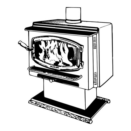
O l y m p i c ( 1 1 9 0 ) W o o d S t o v e a n d F i r e p l a c e I n s e r t Save these instructions for future reference SAFETY NOTICE:... -
Page 2: Important Information
Introduction Important Information Introduction Register your warranty online at: traviswarranty.com Or, mail your warranty card to: Save Your Bill of Sale. - Page 3 General Information Stove Installation INSTALLATION DIAGRAMS Fireplace Insert Installation Preparation for Installation ... 17 Additional Accessories Needed for Installation ... 17 Standard vs. Cook-Top Installations ... 17 Installation Considerations... 17 Table of Contents Operating Your Appliance Maintaining Your Appliance Warranty...
- Page 4 ASHES 36" Type Clay Liner...
- Page 5 Mobile Home This Manual...
- Page 6 Note: Measure side, corner, and back clearances from the stove top. The flue collar protrudes 1" above the stove top Weight: 510 Lbs. with pedestal * For inserts, add 1" for the flue collar. ** See "Fireplace Requirements" for details on fireplace insert installation.
-
Page 8: Floor Protection Requirements
Floor Protection Requirements Stove Placement Requirements Clearances Reduced clearance installations require one of the chimneys and connectors listed below:... -
Page 10: Chimney Requirements
Mobile home installations must use the the reduced clearance connector clearances listed in this manual under “Additional Requirements for Mobile Home Installations”. Stove Clearance (as outlined in this manual) -
Page 11: Chimney Termination Requirements
When using outside air, find a location where the chimney and outside air hole do not interfere with structural members of the home. Pedestal (with insulation) directs air to the stove. Air may be drawn from a ventilated crawl space or use an air duct. -
Page 12: Alcove Installation Requirements
Alcove Installation Requirements Non-combustible alcove construction (on walls and ceiling) - see the explanation above. Ventilated air space 3 1/2" thick non- combustible material 1" Min. Non-combustible reinforcer... -
Page 13: Mobile Home Requirements
Mobile Home Requirements Straight Installations NOTE: Measure clearances to the stove top. Corner Installations 12-1/4” Min. Minimum Connector Clearance (as outlined above) Minimum Stove Clearance (as outlined above) - Page 14 Minimum Air Space to Combustibles (See Chimney Manufacturer's Instructions - usually 2") Minimum 15' Maximum 33' Stove Clearances (See the section "Stove Placement Requirements" for more details) Follow the chimney manufacturer's instructions and clearances for roof penetrations. A storm collar, flashing, and...
- Page 15 Follow the chimney manufacturer's instructions and clearances for wall penetrations. A wall radiation shield (thimble) is required. Stove Clearances (See the section "Stove Optional Placement Requirements" insulated for more details) chase Cap and flashing prevents water from entering The liner must be stainless steel connector or flexible vent.
- Page 16 Min. 18" etc.). Damage must be repaired clearance prior to installation. The chimney to ceiling must be 15' to 33' tall. See the section "Stove Placement Requirements" for minimum clearances required. Chimney connector sections See the section "Floor Protection Requirements"...
- Page 17 The top air chamber extension is shipped separately with the heater (see the following page for details). When installed, the unit is considered a “Standard Model” for Insert Placement and Fireplace Requirements. If it is not installed, the unit is considered a “Cook-Top Model” for Insert Placement and Fireplace Requirements.
- Page 18 3. Attach the grill to the air chamber top. Attach the bypass extension rod included in the owner’s kit to the damper yoke. Attach the bypass pull ring to the extension rod to complete the installation. Remove and discard the bypass extension rod attached to the stove (keep the pull ring).
- Page 19 Minimum Fireplace Size Height (front) Height (rear) Width (front) Width (rear) Depth Hearth Depth* Hearth Width Facing Width Facing Height with Mantel Shield Mantel Height with Mantel Shield * This is the distance the insert protrudes from the fireplace opening plus the required 16" of hearth extension.
- Page 20 Side Wall Minimum Clearances Sidewall to Insert Side Facing Top Facing Mantel to Insert Hearth (Front)* Hearth (Side) Front of Insert Extension onto Hearth * Does not include the distance the insert extends onto the hearth (dimension "x"). Standard Model 15"...
- Page 21 This distance is the hearth step-up. The leveling bolts should stick out this far from the Fireplace base of the insert. Hearth The leveling bolts go into the holes at the rear corners of the insert.
- Page 22 Damper See the dimensions to determine the location of the center of the Firebox flue. Block-Off Plate Template 2" Flanges Measurement "A" (for attaching the block-off plate) Measurement "B" See the dimensions to determine the location of the center of the flue. Measurement "C"...
- Page 23 Install a non-combustible cover plate to prevent water from entering the chimney NOTE: This installation may be used with a masonry or zero clearance fireplace. The requirements in the section "Masonry Fireplace Requirements" or "Zero Clearance Fireplaace Requirements" must be fulfilled prior to installation.
- Page 24 NOTE: This installation may be used with a masonry fireplace only. The requirements in the section "Masonry Fireplace Requirements" must be fulfilled prior to installation. Flue Liner Combustible Mantle Surround Panels with insulation (see "Surround Panels" installation instructions in the back of the manual) See the section "Insert Placement Requirements"...
- Page 25 2 to 4 hours Turn the handle clockwise to un-latch. Swing the door open.
- Page 26 Use the included pull tool to operate the bypass rod Bypass Pulled Out Used for starting and re-loading Bypass Pushed In Used for normal operation...
- Page 28 Use the air control to change the burn rate. Low Burn High Burn (air control closed) (air control open) ASHES...
- Page 29 CONTROL Creaks and Clicks: The 3/16" and 1/4" steel may creak or click when the stove heats up and cools down - this is normal. Blower Sounds: The blower will make a slight "humm" as it pushes air through the stove.
-
Page 30: Hints For Burning
Wood Cut wood to length and Store the wood off the ground in a chop into quarters. covered area. Allow for airflow around the wood to dry the wood. Air Flow Wood Leads Less More Heat Heat Leads More Smoke and Creostoe Air Flow Leads... - Page 32 Allow the stove to fully cool. Apply glass cleaner or soapy water to the inside of the glass. Wipe with newspaper or a paper towel. For Stubborn Creosote: Dip newspaper or a paper towel in cool ashes and wipe it on the glass. The ash acts as a light abrasive.
- Page 33 Exploded View Door Handle Washers Use a 9/16" Door Frame socket wrench to remove this nut. Use wood stove gasket cement to re-adhere loose gasket. Severely frayed or thread-bare gasket should be replaced. Door Cam Adjustment: To tighten, remove a washer from the inside of the door frame.
- Page 34 Touch-Up P a i n t BOTTOM OF Use a vacuum cleaner to remove any STOVE buildup on the screens of the blower.
- Page 35 5/16" Nutdriver Door Shell - Brass Cross Section Door Gasket - Adhere with gasket cement. Glass Clip Screw Glass Clip Glass Clip Gasket 99300502 Door Frame Make sure there is a gap around the edge of the glass Glass Gasket Glass 9/16"...
-
Page 36: Maintaining Your Appliance
Maintaining Your Appliance Firebox Parts ID # Description Part # ID # Description Part # Floor and Side Firebrick Removal & Replacement Do not pry firebrick - they chip and crack easily. - Page 37 Air Tube Collar Air Tube Remove the left pin on the air tube collar Roll Pin Slide the air tube to the left, swing it down and remove from the firebox.
-
Page 39: Freestanding Installation
Olympic (1190) PREVENT HOUSE FIRES - Install and use only in accordance with the Avalon 1190 owner’s manual. Contact your local building or fire officials about restrictions and installation inspection in your area. Refer to local building codes and the chimney manufacturer’s instructions for precautions required for passing a chimney through a combustible wall or ceiling. - Page 40 These rubber-tipped bolts are for leveling the stove. Make sure they contact the floor. Do not adjust with weight on the legs, the rubber tips may tear.
- Page 41 26" The hole for outside air must fall underneath the pedestal base. The faceplate of the 1190 is 3/4" in front of the front edge of the pedestal Screen is used to prevent rodents from entering. Staples are used to attach the screen to the floor.
-
Page 42: Rear Blower Installation
Wire Clip The blower attaches to the stove with the three included screws. Use a 3/8” socket driver or wrench. NOTE: Prior to attaching the blower, tuck all excess wire into the area inside the blower. - Page 43 Air Control Rod The cover plate has a clip which attaches it underneath the air control. Use a Bottom of Stove screwdriver to pry out the knock-out. Attach the air boot with the two screws included with the kit.
- Page 44 PART # 99300312 99300313 99300314 Avalon Pendleton-45 and Rainier-45: Remove the brass trim along the top of the stove. Attach the side panels with Side the included screws (hint: Panel pre-thread the holes prior to installing the panels).
- Page 45 Button Plug for Air Control Rod (For the Rainier (945/990) and Olympic (1190) ake sure the wires run over he top of the blower housing nd are not damaged when the lower is installed.