
Related Manuals for Philips DVR1EP08


Summary of Contents for Philips DVR1EP08
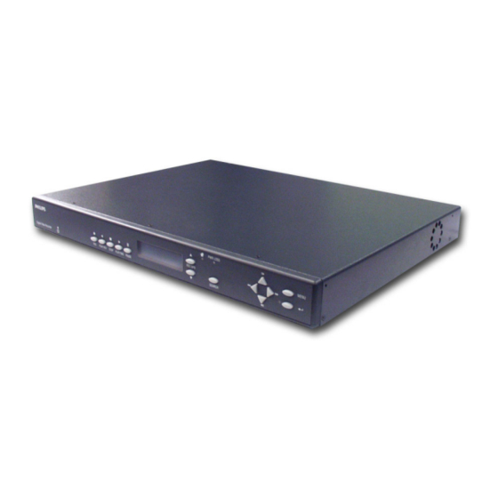
- Page 1 DVR1 Series Single Channel, Color Digital Video Recorder Applicable Models: DVR1EP08, DVR1EP16, DVR1EP32, and DVR1EP32A Philips Communication, Security & Imaging...
-
Page 2: Important Safeguards
IMPORTANT SAFEGUARDS 1. Read Instructions - All the safety and operating instructions should be read before the unit is operated. 2. Retain Instructions - The safety and operating instructions should be retained for future reference. 3. Heed Warnings - All warnings on the unit and in the operating instructions should be adhered to. -
Page 3: Safety Precautions
SAFETY PRECAUTIONS CAUTION: TO REDUCE THE RISK OF ELECTRICAL SHOCK, DO NOT OPEN COVERS. NO USER SERVICEABLE PARTS INSIDE. REFER SERVICING TO QUALIFIED SERVICE PERSONNEL. The lightning flash with an arrowhead symbol within an equilateral triangle is intended to alert the user to the presence of uninsulated "dangerous voltage"... -
Page 4: Precauciones De Seguridad
SICHERHEITSVORKEHRUNGEN VORSICHT: UM EINEN ELEKTRISCHEN SCHLAG ZU VERMEIDEN, ABDECKUNG NICHT ENTFERNEN. WARTUNGEN ALLER ART QUALIFIZIERTEM PERSONAL BRLASSEN. Das Blitzsymbol im gleichseitigen Dreieck soll den Benutzer auf nicht isolierte “Hochspannung” im Gehäuse aufmerksam machen, die eventuell stark genug ist, um einen elektrischen Schlag zu verursachen. Das Ausrufezeichen im gleichseitigen Dreieck soll den Benutzer auf wichtige Bedienungs- und Wartungsanleitungen in der dem Gerät beigefügten... - Page 5 VEILIGHEIDSMAATREGELEN VOORZICHTIG GEVAAR VOOR ELEKTRISCHE SCHOK. NIET OPENEN! GEVAAR: OPEN DEZE BEHUIZING NIET, TENEINDE HET RISICO VAN ELEKTRISCHE SCHOKKEN TE VOORKOMEN. BINNENIN BEVINDEN ZICH GEEN DOOR DE GEBRUIKER TE REPAREREN ONDERDELEN. RAADPLEEG VOOR REPARATIE GEKWALIFICEERD SERVICEPERSONEEL. Het symbool van een bliksem met pijlpunt in een gelijkzijdige driehoek is bedoeld om de gebruiker te waarschuwen voor de aanwezigheid van een niet geïsoleerde ‘gevaarlijke spanning’...
- Page 6 MEDIDAS DE SEGURANÇA CUIDADO RISCO DE CHOQUE ELÉCTRICO. NÃO ABRIR! CUIDADO: PARA REDUZIR O RISCO DE CHOQUE ELÉCTRICO, NÃO ABRA AS TAMPAS. O INTERIOR NÃO CONTÉM PEÇAS QUE NECESSITEM DE MANUTENÇÃO. A MANUTENÇÃO DEVE SER EFECTUADA POR PESSOAL DE ASSISTÊNCIA TÉCNICA QUALIFICADO.
-
Page 7: Table Of Contents
TABLE OF CONTENTS SECTION 1: INTRODUCTION TO THE DVR1 SERIES DIGITAL VIDEO RECORDERS Guide to This Manual ...9 Unpacking ...9 Understanding the DVR1 Series ...9 SECTION 2: INSTALLING THE DVR1 ...10 Mounting ...10 Connecting the DVR1 ...10 SECTION 3: GUIDE TO THE DVR1 CONTROLS ...13 DVR1 Front Panel Controls ...13 DVR1 Front Panel Display ...13 Navigating with the DVR1 Controls ...14... - Page 8 Connection of Alarm Contact ...33 Programming the REO System Monitor ...34 Programming the DVR1 ...34 Remote Viewing Considerations ...34 APPENDIX D: INSTALLATION GUIDE FOR THE COMBINED PHILIPS MULTIPLEXER, INTUIKEY KEYBOARD & DVR1 SERIES SYSTEM ...35 Overview ...35 Required Software Version ...35 Installation ...35...
-
Page 9: Section 1: Introduction To The Dvr1 Series Digital Video Recorders
DVR1 SERIES DIGITAL VIDEO RECORDERS Guide to This Manual This manual contains all of the information necessary to safely install, program, and operate Philips’ DVR1 Series Digital Video Recorders. Step-by-step procedures and sample menus guide you through each phase of the DVR1’s setup and programming. -
Page 10: Section 2: Installing The Dvr1
5. RS-232 Serial Port: Serial port for Flash Upgrading of software. Also used for external control of unit. NOTE: The RS-232 port does NOT work with a modem. Use a Null Modem type cable (Philips S1385 cable) to connect to this port. - Page 11 2. Connect all peripherals (e.g. cameras, monitors, etc.) to the corresponding inputs/outputs on the DVR1 rear panel. CAUTION: DO NOT connect both S-video and Composite inputs at the same time. A hardware conflict will occur, which could damage the unit. 3.
- Page 12 Alarm Out: The Alarm Output is activated when a teletext alarm is read, or while the Alarm Input is active. The Alarm output is only active for the duration of the alarm event. Record Start In: When activated, this connection places the unit in record mode. Compatible with the Disk End Out signal from a second unit.
-
Page 13: Section 3: Guide To The Dvr1 Controls
SECTION 3: GUIDE TO THE DVR1 CONTROLS Before attempting DVR1 programming, you should become familiar with the function of the DVR1 controls. This section provides a summary of the front panel controls and indicators, as well as hints for navigating the DVR1 menus and entering values via the front panel controls. -
Page 14: Navigating With The Dvr1 Controls
Navigating with the DVR1 Controls Navigating and entering parameter values with the DVR1 controls are designed to be easy and intuitive. Most menus use the same navigation for programming operations. Pull-down Menus Pull-down menus are the top-level menus, and are accessed by pressing MENU. For example, the following DVR1 Main Menu is a pull-down menu. -
Page 15: Section 4: Dvr1 Main Menu Programming
SECTION 4: DVR1 MAIN MENU PROGRAMMING Overview of the DVR1 Main Menu The DVR1 Series Main Menu allows quick and easy programming of vital system data and operating parameters. The following table provides a summary of user actions that are accessible via the DVR1 Main Menu. User Action Set Time/Date Configure Alarms... -
Page 16: Configuring Scheduled Recordings
Configuring Scheduled Recordings Main Menu ➝ Timer Settings This menu allows the scheduling of a timed-recorded event. A sample menu is shown here. START 16:45 7:55 MON-FRI 9:56 SAT-SUN 14:23 MON-SUN 2:23 --:-- EDIT MODE The fields to be programmed in the above menu are as follows: •... -
Page 17: Configuring On-Screen Display Options
Configuring On-screen Display Options Main Menu ➝ Display Settings Use this menu to specify the status information to be displayed on the primary monitor (usually shown in the upper right or upper left corner of the screen). Each of the following parameters may be set ON or OFF for the on-screen display: •... - Page 18 When all required search criteria has been entered, highlight [START SEARCH], then press ENTER. The Archive Search Results window will appear. "ENTER" TO PLAY Use the Left/Right Arrows to navigate the Search Results menu, highlighting the recorded event you wish to select. Use the Up/Down Arrows to select a recorded event by placing [X] in the check box.
-
Page 19: Accessing The Advanced Menu
• Write Once: When the archive device is full, archiving stops. Archiving will resume after the user acknowledges that the archive device is full and that archiving should resume. • No Overwrite: When the archive device is full, archiving stops. Archiving will resume only after a user enters the advanced menu, manually erases the media, and resumes archiving. -
Page 20: Section 5: Dvr1 Advanced Menu Programming
SECTION 5: DVR1 ADVANCED MENU PROGRAMMING Overview of the DVR1 Advanced Menu Enhanced DVR1 operating features are programmed via the Advanced Menu. The following table provides a summary of these actions that are accessed via the DVR1 Advanced Menu. User Action Overwrite the Hard Disk Erase, Delete, and Recover Hard Disk Data Invoke Audio Recording... -
Page 21: Overwriting The Hard Disk
Overwriting the Hard Disk Advanced Menu ➝ Disk Overwrite Mode Use this menu to specify how disk overwrite issues are handled once the hard disk becomes full. Select one of three options: • No Overwrite (i.e., recording stops when the disk is full). An on-screen message indicates when the disk is full and the unit has stopped recording. -
Page 22: Configuring Communications
@ABCDEFGHIJKLMNOPQRSTUVWXYZ [ \ ] ^ BAUD RATE ETHERNET SETTINGS MODEM SETTINGS ETHERNET SETTINGS DISABLE 10. 90.253.000 255.255. 0. 0 10. 90. 0. 1 [OK] NONE KALATEL ROBOT PHILIPS PELCO SANYO PHILIP’S REO NAVCO ATV QSP VISTA VLM BRIGHTNESS CONTRAST SATURATION UNLOCK KEYBOARD LOCK KEYBOARD... -
Page 23: Restoring Factory Defaults
5.11 Restoring Factory Defaults Advanced Menu ➝ Factory Settings Use this menu to restore the DVR1 to the factory defaults. NOTE: When the factory settings are restored, all programmed settings and volume partitions for archive retrieval are erased. The factory password is fixed at 0000. Therefore, you can repeatedly press ENTER, and press ENTER to complete entry and restore the unit to its factory default settings. -
Page 24: Section 6: Operating The Dvr1 Series
SECTION 6: OPERATING THE DVR1 SERIES Operating the DVR1 requires general knowledge in three areas: • Recording • Playback • Searching Certain operating parameters must be set/programmed as part of initial startup of the DVR1. These activities are outlined in the following section. Initial Startup On initial power-up of the DVR1, the following settings must be programmed: •... -
Page 25: Playback
Disk Full Notification This message will appear on the primary monitor to indicate that the unit has stopped recording because the disk is full. In No Overwrite mode, the unit will not record over previously recorded data. To continue recording, the user must acknowledge the disk full message by pressing ENTER, then ERASE (or DELETE). -
Page 26: The Search Interface
Rewind During playback, press REWIND to view the data (in reverse) at a faster than normal rate. Rewind is indicated via the following: • REWIND appears briefly in the upper left-hand corner of the primary monitor • REW appears on the LCD. Pause During playback, press PAUSE to pause playback and display a single frame on-screen. -
Page 27: Section 7: Archiving
SECTION 7: ARCHIVING Archiving Applications Explained The following sections explain the usage of the Extended Archiving, Backup Archiving, and Selective/Manual Archiving applications for the DVR1 Series Digital Video Recorders. 7.1.1 Extended Archiving Applications • Explained: In this application, the DVR is in a Background Archiving Mode. Hence, all recorded video is sent to the archive device in a continuous fashion. -
Page 28: Creating A Cd-Rom With Video Files
Using the DVR’s (DVR1 or DMX) menu system, set the unit for Selective archiving. Remove power from the DVR unit. Apply power to the CD-writer and allow it to initialize. Apply power to the DVR unit. Be sure that the CD-writer is recognized by the DVR unit. This may take a few minutes (to view the archive status, enable the Archive Status display via the menus of the DVR unit). -
Page 29: Section 8: Service And Returns
SECTION 8: SERVICE AND RETURNS Maintenance Programmer maintenance of this unit is limited to external cleaning and inspection. Factory Service Ensure that the cooling vents are not blocked and that the unit is installed in a well ventilated location. In addition, do not place the unit on top of other equipment, which may increase the operating temperature of the unit. -
Page 30: Appendix A: Factory Default Settings
APPENDIX A: FACTORY DEFAULT SETTINGS FUNCTION Time Format Date Format Normal Record Speed Alarm Record Speed Record Quality Disk Overwrite Mode Archive Overwrite Mode Auto Delete Mode Background Archive Mode Input Front Panel Locked Brightness Contrast Saturation Display Current Time and Date Display Record Capacity Display Archive Status Display Last Alarm... -
Page 31: Appendix B: Technical Specifications
APPENDIX B: TECHNICAL SPECIFICATIONS GENERAL Power Supply Input Voltage Power Consumption Operating Temperature Range Relative Humidity Range (Noncondensing) Dimensions Weight CONNECTIONS Ethernet Port Power Connector Accessory I/O Port SCSI-2 Port RS-232 Serial Port S-Video In S-Video Out Composite Video In Composite Video Out CAUTION: Do not connect both video inputs at the same time. - Page 32 ON-SCREEN VIDEO INDICATORS Archive Status End of Data Fast Forward Last Alarm PART NUMBERS Power Supply Accessories PCB Rack Mount Kit Installation Instructions (this manual) Wave Reader Manual Wave Watch Manual Wave Reader Software CD Pause Rewind Play Start of Data Record Capacity Time and Date Reverse Play...
-
Page 33: Appendix C: Reo Quick Install Guide
APPENDIX C: REO QUICK INSTALL GUIDE Introduction This guide provides the steps necessary to install the DVR1 in combination with a REO Multiplexer or REO Switcher Monitor. If you are not familiar with the operations of the DVR1 and the REO Monitor, refer to the corresponding instruction manuals. Required Software Version Ensure that the DVR1 and REO monitor’s software version is equal to or higher than noted below. -
Page 34: Programming The Reo System Monitor
Enter the correct password (default is 0000) and ENTER Press ENTER to access the Advanced Menu Select MULTIPLEXER FORMAT, then ENTER Select PHILIPS REO, then ENTER Press MENU twice to exit. Remote Viewing Considerations The following pertains to the Remote Viewer Software (included with the DVR1; allows Remote Viewing of video via a PC with this software loaded). -
Page 35: Appendix D: Installation Guide For The Combined Philips Multiplexer, Intuikey Keyboard & Dvr1 Series System
This new software simplifies retrieval of the DVR1’s recorded video via the IntuiKey keyboard. Required Software Version Ensure that the keyboard, DVR1, and Philips Multiplexer software versions are equal to or higher than those noted below. Software for these products is available at www.philipscsi.com. -
Page 36: Dvr1 Keyboard Menus
DVR1 Keyboard Menus There are two new keyboard menus that provide direct access to the DVR1 menus and its recorded video (refer to the keyboard’s instruction manual for further information on keyboard menus). DVR1 Controls 1.4.1 DVR1 Controls Menu To view the DVR1 CONTROLS menu, at the Keyboard’s MULTIPLEXER MAIN MENU, select RECORDER CONTROLS, then DVR1 CONTROLS. -
Page 37: Dvr1 Playback Controls Menu
1.4.2 DVR1 Playback Controls Menu Below is a list of the new Keyboard Softkey buttons for the DVR1 Playback Controls menu along with an explanation of the functions they perform. Softkey Exit Full, Quad, Multi Pause, Play Forward, Play Reverse, Frame Advance, Frame Reverse, Fast Reverse, Fast Forward, Increase Speed, Decrease Speed... -
Page 38: Appendix E: Rs-232 Remote Protocol
APPENDIX E: RS-232 REMOTE PROTOCOL Supported Command Sequences The DVR1 supports the following command sequences, entered via PC once communication has been established between the PC and the DVR1. The Baud Rate should be set at 9600 Baud, with 1 Stop Bit, 8 Data Bits, and Parity at None. All byte values entered at the PC must be in hexadecimal values. - Page 39 SET CLOCK Example: In this example, 14:39 on December 25, 2000 is used to demonstrate the Set Clock Command String. Notation Used in Value Column Year Character #1 Year Character #2 Month Character #1 Month Character #2 Day Character #1 Day Character #2 Hour Character #1 Hour Character #2...
- Page 40 Intel Corporation. 3935 890 36813 03-02 © 2003 Bosch Security Systems, Inc. Printed In U.S.A. All Rights Reserved. Philips Philips Electronics N.V. Updated January 06, 2003. Data subject to change without notice. Refer to www.philipscsi.com for latest information.