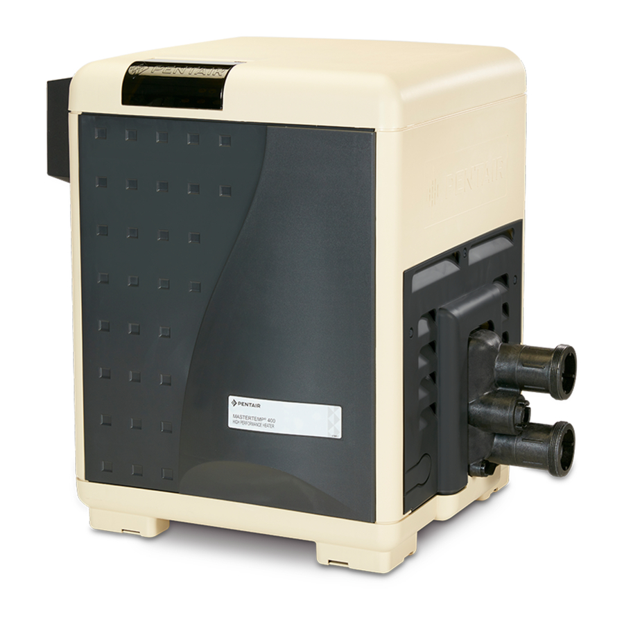
Pentair Pool Products MASTERTEMP 250K BTU/HR Installation And User Manual
Pool and spa heater 120/240 vac natural gas/lp gas
Hide thumbs
Also See for MASTERTEMP 250K BTU/HR:
- Installation and user manual (38 pages) ,
- Operation & installation manual (56 pages)
Table of Contents
Advertisement
Available languages
Available languages
MasterTemp
POOL AND SPA HEATER
120/240 VAC NATURAL
GAS/LP GAS
I N S T A L L A T I O N
a n d
U S E R ' S G U I D E
MODELS
200K BTU/HR
250K BTU/HR
300K BTU/HR
400K BTU/HR
SPECIAL INSTRUCTIONS TO OWNER
Retain this manual for future reference.
This manual supplies information for the installation, operation,
and servicing of the appliance. READ AND REVIEW THIS
MANUAL COMPLETELY before proceeding with an installation.
Its use will reduce service calls and chance of injury and will
lengthen product life.
If the information in these instructions is not followed exactly, a fire
or explosion may result causing property damage, personal injury or death.
Call (800) 831-7133 for additional free copies of these instructions.
FOR YOUR SAFETY
Do not store or use gasoline or other flammable vapors and liquids in the vicinity of this or
any other appliance.
WHAT TO DO IF YOU SMELL GAS
• Do not try to light any appliance.
• Do not touch any electrical switch; do not use any phone in your building.
• Immediately call your gas supplier from a neighbor's phone. Follow the gas supplier's
instructions.
• If you cannot reach your gas supplier, call the fire department.
Installation and service must be performed by a qualified installer, service agency or the gas
supplier.
472592 Rev. A (04/04/06)
Natural
Propane
460730
460731
460732
460733
460734
460735
460736
460737
IMPORTANT SAFETY INSTRUCTIONS
READ AND FOLLOW ALL INSTRUCTIONS
SAVE THESE INSTRUCTIONS
WARNING
TM
®
C E R T I F I E D
®
Advertisement
Chapters
Table of Contents

Related Manuals for Pentair Pool Products MASTERTEMP 250K BTU/HR


Summary of Contents for Pentair Pool Products MASTERTEMP 250K BTU/HR
- Page 1 MasterTemp POOL AND SPA HEATER 120/240 VAC NATURAL GAS/LP GAS I N S T A L L A T I O N a n d U S E R ’ S G U I D E MODELS Natural 200K BTU/HR 460730 250K BTU/HR 460732...
-
Page 2: Table Of Contents
INSTALLATION, OPERATION AND SERVICE MANUAL TO INSTALLER: Affix these instructions adjacent to the heater. TO CONSUMER: Retain these instructions for future reference. FOR YOUR SAFETY - This product must be installed and serviced by a professional service technician, qualified in pool heater installation. Improper installation and/or operation could create carbon monoxide gas and flue gases which could cause serious injury or death. -
Page 3: Safety
Any additions, changes, or conversions required in order for the appliance to satisfactorily meet the application needs must be made by a Pentair dealer or other qualified agency using factory specified and approved parts. The heater is available for use with natural gas or LP (propane) gas only. -
Page 4: Description Of The Heater
The heater may not be installed within five feet of the inside surface of a pool or spa unless it is separated by a solid fence, wall or other permanent barrier. A Propane (LPG) fired heater must not be installed in a garage in Massachusetts, by order of the Massachusetts State Fire Marshall. -
Page 5: Spa Temperature Caution
C. Use only your hand to turn the gas control on or off. Never use tools. If you cannot change the ON/OFF setting by hand, don’t try to repair it, call a qualified service technician. Force or attempted repair may result in fire or explosion. -
Page 6: To Switch Off Gas To The Appliance
8. Push the toggle switch away from you to switch the gas on. 9. Replace the Door Access Panels. All panels must be in place when operating the heater. 10. Set 3-way valves on inlet and outlet to pool or spa, as appropriate. -
Page 7: After Start-Up
The SERVICE SYSTEM light indicates that there is insufficient water flow to the heater. If the pump is oper- ating, this usually indicates that the filter and/or skim- mers should be cleaned (some filters may require back- washing). If the light remains on after the filter/skimmers have been serviced, the system should be checked by a qualified service technician. -
Page 8: Installation Instructions
CARE AND MAINTENANCE MAINTENANCE INSTRUCTIONS Risk of fire or explosion from flammable WARNING vapors. Do not store gasoline, cleaning fluids, varnishes, paints, or other volatile flammable liquids near heater or in the same room with heater. The following maintenance is recommended every six months and at the start of every swimming season: 1. -
Page 9: Outdoor Installation
OUTDOOR INSTALLATION INSTRUCTIONS For heaters located outdoors, using the built-in stackless venting system. Risk of explosion if a unit burning propane WARNING gas is installed in a pit or other low spot. Propane is heav- ier than air. Do not install the heater using propane in pits or other locations where gas might collect. -
Page 10: Outdoor Shelter/Indoor Installation
CONTROL PANEL INDEXING The exhaust discharges vertically from outside the vent cover. The heater control panel assembly located on the top panel can be rotated to any of three positions for convenient access to the panel as follows: 1. Remove the bolts from the door panels. Remove both door panels. - Page 11 NOTICE: Combustion air contaminated by corrosive chemical fumes can damage the heater and will void the warranty (See Table 1 below). HEATER CLEARANCES – OUTDOOR SHELTER (Canada) or INDOOR (U.S.) The following clearances must be maintained from com- bustible surfaces: TOP...3 ft.
- Page 12 OUTSIDE VENT COVER REMOVAL The heater is supplied from the factory with a built-in stackless outside vent for outdoor installation. Remove the outside vent cover for outdoor shelter installation. VERTICAL VENTING - NEGATIVE PRESSURE (See Figures 11 and 12) Vent the heater vertically in a negative pressure (positive draft) system in accordance with the National Fuel Gas Code, ANSI Z223.1/NFPA 54 and/or CSA B149.1, Natural Gas and Propane Installation Codes,...
- Page 13 5. Use Listed firestop for floor and ceiling penetrations. Use Listed thimble for wall penetrations. Use a Listed roof flashing, roof jack, or roof thimble for all roof penetrations. Do not fill the space around the vent (that is, the clear air space in the thimble or firestop) with insulation.
- Page 14 Table 4: Vent Termination Height vs. Roof Pitch – U.S. Roof Pitch Flat to 6/12 6/12 to 7/12 >7/12 to 8/12 >8/12 to 9/12 >9/12 to 10/12 >10/12 to 11/12 >11/12 to 12/12 >12/12 to 14/12 >14/12 to 16/12 >16/12 to 18/12 >18/12 to 20/12 >20/12 to 21/12 * Vent must be at least eight (8) feet away from nearest vertical...
-
Page 15: Water Connections
4' Min. 4' Min. Vent Vent Termination Termination 4' Min. 4' Min. 1' Minimum Gas Meter above snow or Forced Air finished grade Inlet 3' Minimum clearance if (whichever is horizontal distance to higher) exhaust opening is less than 10 feet. FIGURE 13: U.S. - Page 16 Install a check valve to prevent back-siphoning through the heater when the pump is off. NOTICE: Improper operation of chemical feeders can cause severe damage to the heater which is not covered by the warranty. Install the chemical feeder downstream of the heater (see “Water Chemistry,”...
- Page 17 Warm water out 1. Set Manual Bypass Valve 2. Remove handle FIGURE 16: Manual bypass valve Verify proper operation of the water pressure switch at the start of every season and every six months thereafter by the following steps: 1. Lower the thermostat setting to turn off the heater. 2.
-
Page 18: Pressure Relief Valve
PRESSURE RELIEF VALVE Canadian code requires and some U.S. local codes may require installation of a pressure relief valve. Purchase separately and install a 3/4" pressure relief valve comply- ing with the ANSI/ASME Boiler and Pressure Vessel Code, having a capacity equal to the Btu/hr rating of the heater. The relief pressure of the valve MUST NOT EXCEED 50 PSI. - Page 19 Instructions For Checking the Gas Pressure Through the Combination Gas Control Valve WARNING Risk of fire and explosion. Improper installation, adjustment, alteration, service, or main- tenance of the Combination Gas Control Valve can lead to fire or explosion, causing loss of life, per- sonal injury, or property damage.
-
Page 20: Gas Connections
GAS CONNECTIONS The heater requires a gas supply of not less than 4" (10.2cm) wc and not more than 14" (35.6cm) wc. Gas supply pressures outside of this range may result in improper burner operation. A minimum flowing or dynamic inlet pressure of 4" (10.2cm) wc is required to maintain input rating. - Page 21 Connect the L1 of the power supply to the black wire, the L2 or neutral lead to the red wire, and the ground wire to the green wire. A time clock controlling the filter pump should have a low-voltage Fireman’s Switch that switches off the heater at least 15 minutes before shutting off the pump.
- Page 22 6. Reinstall the access door panels. The fuse for the Fireman’s Switch is a 1.25 amp 1-1/4x1/4" fast blow fuse, available locally. MAXIMUM TEMPERATURE SET POINT 1. Unbolt and remove the Door Panels (see Figure 3, Page 5). 2. Access the control panel board on the underside of the top cover.
- Page 23 Initial Troubleshooting Only qualified, trained service technicians with appropriate test equipment should service the heater. Remember that all parts of the system affect heater operation. Before starting this troubleshooting procedure, make sure that the pump is running correctly, that there are no blockages in the system, that the valves are correctly set and that the time clock is correctly set and is running.
- Page 24 Heater Will Not Fire - A Start Is green “SPA” or “POOL” LED “on” Check that correct 12-pin plug is installed (red is 240V, black is 120V) If plug is not installed: Install correct plug. 240V plug in 120V circuit: Replace with correct plug.
- Page 25 Heater Will Not Fire - B Start Is red “SERVICE HEATER” LED “on” CONTINUE Is red “SERVICE SYSTEM” LED on? Verify that pump is on, filter is not blocked, and the water flow is above the minimum requirement. With pump running, adjust Water Pressure Switch to lower pressure until ‘SER- VICE SYSTEM”...
-
Page 26: Troubleshooting
Heater Will Not Fire - C Start Is “SERVICE HEATER” LED “on”? If any red diagnostic LED’s (AGS, AFS, SFS, HLS, PS, or THERMISTOR) come “on”, go to to Pages 28 and 29. CONTINUE Did burner fire at all? Go to “BURNER TROUBLESHOOTING”... - Page 27 Heater Will Not Fire - D IMPORTANT! READ ME FIRST!! IMPORTANT! READ ME FIRST!! If your heater is correctly connected to 240 Volts AC, The Ignition Control Module (ICM) will convert the 240VAC to an intermittent pulse to the ignitor. Digital meters don’t read this type of signal well.
-
Page 28: Diagnostic Led’s
Diagnostic LED’s: AGS, AFS, HLS, PS, THERMISTOR AGS or HLS “on” Replace High Limit Switch (HLS) or Automatic Gas Shutoff (AGS) CONTINUE If problem persists, verify proper operation of Internal Bypass Valve and Thermal Governor, and check for Heat Exchanger blockage. PS “on”... -
Page 29: Sfs Diagnostic Led’s
Diagnostic LED’s: SFS SFS “on” Heater starts and runs OK, but temperature of exhaust climbs to 450º–500º in 3–5 minutes. Heater starts after several tries, exhaust temperature stays below 250º. Heater doesn’t start at all (exhaust stays cold). Check pressure and volume of fuel supply Disconnect the sensor and check continuity across its... - Page 30 Burner Troubleshooting SYMPTOM Loud, high-pitched whine Flame is “fluttery.” Exhaust may have acrid smell or burner may fail to stay lit. Burner pulsates or surges, especially on ignition. Combustion appears normal, but flame does not stay lit. Heat Exchanger Troubleshooting SYMPTOM Boiling in heat exchanger.
-
Page 31: Repair Parts
For complete Water System parts breakdown (Key Nos. 10 through 13), see Page 34 Repair Parts are available from your Pentair dealer. If your dealer cannot supply you, call Customer Support at 1-800-831-7133. For complete Burner System parts breakdown (Key Nos. 5 through 9),... - Page 32 For Heater mounting bolts and clamps, purchase separately Bolt Down Bracket Kit, Part No. 460738.
- Page 33 REPAIR PARTS – BURNER SYSTEM Part Description Combination Gas Control Valve Kit 3/4" Union Gas Orifice • Gas Orifice Kit – NG (Incl. Key Nos. 3 and 4)† • Gas Orifice Kit – Propane (Incl. Key Nos. 3 and 4)† •...
- Page 34 REPAIR PARTS – WATER SYSTEM Part Description Tube Sheet Coil Assembly Kit (NA, LP Series) (Includes Key No.3) Manifold Kit (Includes Key Nos. 3-14, 21, and Key Nos. 7-9 in “Electrical System”, Page 35 Coil/Tubesheet Sealing O-Ring Kit Manifold Bottom Plate Manifold O-Ring •...
-
Page 35: Repair Parts
REPAIR PARTS – ELECTRICAL SYSTEM Part Description Heater Display Cover Igniter Bracket Igniter/Igniter Gasket Kit Incl. Key Nos. 4 and 5) Igniter Gasket Automatic Gas Shutoff Switch (AGS) High Limit Switch Thermistor Terminal Board Fireman’s Switch Fuse (1.25A, 1-1/4") Ignition Control Module Transformer, 115/230V Air Flow Switch Control Board Kit (NA, LP Series) -
Page 36: Wiring Diagrams/External Control Interface
Pool Heater Wiring Connection Diagram AGS Switch Stack Flue Sensor Gas Valve External Control Interface Circuit Disabled, Heater Membrane Pad Enabled External Control Interface External Control Interface Circuit Enabled, "Pool On" and "Spa On" Keys Disabled. "OFF" Key on Membrane Pad Remains Functional. Plug –12 pin 120V –... - Page 37 Pool Heater Electrical Schematic Ladder Diagram 24 VAC COM NO SWITCH THERMISTOR SENSOR NOTES: ARE CONNECTED ON THE IGNITION MODULE. 2. ) PIN AND SOCKET CONNECTOR. 3. ) IF ANY OF THE ORIGINAL WIRES AS SUPPLIED WITH THE APPLIANCE MUST BE REPLACED, THEY MUST BE REPLACED WITH TYPE 105C OR ITS EQUIVALENT.
-
Page 38: Save These Instructions
Trademarks and disclaimers: MasterTemp and the Pentair Pool Products and Pentair Water Pool and Spa logos are trade- marks of Pentair Water Pool and Spa, Inc. Other trademarks and trade names may be used in this document to refer to either the entities claiming the marks and names or their products. - Page 39 MasterTemp CHAUFFE-PISCINE/SPA C.A. 120/240 VOLTS AU GAZ NATUREL/GPL N O T I C E D ’ U T I L I S A T I O N INSTALLATION, FONCTIONNEMENT ET PIÈCES MODÈLES Naturel 200K BTU/h 460730, 250K BTU/h 460732, 300K BTU/h 460734, 400K BTU/h 460736,...
- Page 40 NOTICE D'UTILISATION, DE FONCTIONNEMENT ET D'ENTRETIEN Chauffe-piscine/spa au gaz modèles SR INSTALLATEUR : Ces instructions doivent être gardées à proximité du chauffe-piscine/spa. CONSOMMATEUR : Ces instructions doivent être conservées pour pouvoir s'y reporter ultérieurement. SÉCURITÉ - Ce produit doit être installé et entretenu par un technicien professionnel et qualifié...
-
Page 41: Conditions Et Spécifications Générales
INSTRUCTIONS CONCERNANT LA SÉCURITÉ (suite) AVERTISSEMENT Cet appareil est équipé d'une soupape à gaz non conventionnelle qui a été réglée à l'usine à une pression d'admission de -0,2 pouce à la colonne d'eau. Une mauvaise installation, un mauvais réglage, toute modification ou un mauvais entretien de cette soupape risquent de causer des dommages matériels, des blessures corporelles, voire la mort. -
Page 42: Description Du Chauffe-Piscine/Spa
Ce chauffe-piscine/spa doit être installé à au moins cinq pieds de la paroi intérieure d'une piscine ou d'un spa, si une clôture, un mur ou toute autre barrière massive permanente ne les sépare pas. Dans l’état du Massachusetts, un chauffe-piscine/spa fonction- nant au gaz de pétrole liquéfié... -
Page 43: Précautions À Prendre Concernant La Température Des Spas
N’ouvrir et ne fermer la commande du gaz qu’à la main. Ne jamais utiliser d’outils. Si le réglage MARCHE-ARRÊT ne peut pas être modifié à la main, ne pas essayer de réparer. Appeler un technicien qualifié. Forcer ou essayer de réparer risque de causer un incendie ou une explosion. -
Page 44: Pour Couper L'arrivée De Gaz Au Chauffe-Piscine/Spa
Attendre cinq (5) minutes pour que tout le gaz soit évacué. Si on sent une odeur de gaz, ARRÊTER! Suivre les instruc- tions «B» figurant sous «Avant la mise en marche» (page 4). Si on ne sent pas d'odeur de gaz, passer à la prochaine opération. -
Page 45: Après La Mise En Marche
Le témoin HEATING (CHAUFFAGE) s'allume et reste allumé pendant que le brûleur fonctionne. Il clignote si l'eau du chauffe-piscine/spa doit être chauffée mais que le brûleur ne s'allume pas. Si le témoin est allumé et que le brûleur ne s'al- lume pas, un des témoins «service»... -
Page 46: Entretien/Instructions D'entretien/Hiverisation
ENTRETIEN INSTRUCTIONS D'ENTRETIEN AVERTISSEMENT Les vapeurs inflammables risquent de causer un incendie ou une explosion. Ne pas entreposer d'essence, de liquides de nettoyage, de vernis, de peinture ou tout autre liq- uide inflammable volatil à proximité du chauffe-piscine/spa ni dans la même pièce que le chauffe-piscine/spa. Il est recommandé... - Page 47 INSTRUCTIONS CONCERNANT LES INSTALLATIONS EXTÉRIEURES Chauffe-piscine/spa installés à l'extérieur et utilisant le système d'évacuation des gaz brûlés sans cheminée incorporé. AVERTISSEMENT Risque d’explosion si un chauffe-piscine/spa fonctionnant au propane est installé dans une fosse ou dans une zone creuse. Le propane est plus lourd que l'air. Ne pas installer un chauffe-piscine/spa fonctionnant au propane dans une fosse ou dans un endroit où...
- Page 48 INDEXAGE DU BLOC DE COMMANDE Les gaz brûlés sont refoulés verticalement par l'extérieur du couvercle d'évacuation.Le bloc de commande du chauffe- piscine/spa, qui se trouve en haut de l’enceinte, peut-être tourné vers n’importe lequel des trois côtés pour pouvoir y accéder avec facilité.
- Page 49 CHAUFFE-PISCINES/SPAS INSTALLÉS À L'EXTÉRIEUR DANS UN ABRI Les dégagements suivants doivent être respectés avec toutes les surfaces combustibles : Au-Dessus...1 mètre (3 pieds) Côté échappement...15 cm (6 pouces) Tuyaux d’entrée et de sortie...5M (18 in.) Panneau de la Porte d’Accès...30 cm (12 in) Noter : pour y acceder pour l’entretien, il faut laisser au moins 60 cm d’espace libre pour une des deux panneaux.
- Page 50 DÉPOSE DU COUVERCLE EXTÉRIEUR DU CONDUIT DES GAZ BRÛLÉS Pour les installations extérieures, le chauffe-piscine/spa est livré avec une évacuation extérieure incorporée sans conduit. Si le chauffe-piscine/spa est installé à l'extérieur, déposer le couver- cle extérieur du conduit d'évacuation des gaz brûlés. ÉVACUATION À...
- Page 51 gaz brûlés installés à l'horizontale doit être d'au moins 1/4 de pouce par pied (2 cm par mètre) à partir du chauffe- piscine/spa. Installer un collecteur de condensats homo- logué au point bas, là où les condensats peuvent s'accu- muler. Brancher le collecteur de condensats sur un rejet à l'égout avec un tuyau rigide ou un tube pour températures élevées, comme un tube en caoutchouc de silicone ou en caoutchouc éthylène-propylène-diène –...
- Page 52 Tableau 4 : Hauteurs de la terminaison du con- duit d’évacuation des gaz brûlés par rapport à la pente du toit – États-Unis Pente du toit Plate à 6/12 6/12 à 7/12 >7/12 à 8/12 >8/12 à 9/12 >9/12 à 10/12 >10/12 à...
-
Page 53: Branchements D'eau
Terminaison du conduit 4 pi minimum 4 pi minimum d’évacuation des gaz Terminaison du conduit d’évacuation brûlés 4 pi des gaz brûlés minimum 4 pi minimum Au moins 1 po Compteur à gaz au-dessus du Admission niveau d’accu- d’air pulsé mulation de la Dégagement minimum de 3 pi neige ou du... - Page 54 S'assurer que la tuyauterie de refoulement du chauffe- piscine/spa ne comporte aucune vanne ou obstruction du débit qui risquerait d'empêcher l'eau de circuler dans le chauffe- piscine/spa (sauf comme il est indiqué ci-dessous). Pour que la circulation de l'eau se fasse dans la piscine ou le spa, utiliser un répartiteur de débit.
- Page 55 Attendre une minute. Le témoin «Service System» doit s'allumer, mais le brûleur ne doit pas s'allumer et la soufflante ne doit pas démarrer. Si la soufflante démarre ou si le brûleur s'allume, ou si le témoin «Service System» ne s'allume pas, le manostat fonctionne mal. Appuyer immédiatement sur la touche OFF du bloc de commande pour arrêter le brûleur et appeler un technicien qualifié...
-
Page 56: Soupape De Sûreté
SOUPAPE DE SÛRETÉ Le code canadien exige et, aux États-Unis certains codes des municipalités peuvent l’exiger, l’installation d’une soupape de sûreté. Acheter et installer séparément une soupape de sûreté de 3/4 po ayant une capacité égale au débit en Btu/h du chauffe-piscine/spa et conforme au code ANSI/ASME «... -
Page 57: Instructions Pour Vérifier La Pression Du Gaz Par La Soupape À Gaz Mixte
Instructions pour vérifier la pression du gaz par la soupape à gaz mixte AVERTISSEMENT Risque d'incendie et d'explosion. Toute mauvaise installation, tout mauvais réglage, toute trans- formation, tout mauvais entretien de la soupape à gaz mixte peuvent provoquer un incendie ou une explosion et causer la mort, des blessures corporelles ou des dom- mages matériels. -
Page 58: Branchements Du Gaz
BRANCHEMENTS DU GAZ L'arrivée du gaz au chauffe-piscine/spa doit être d'au moins 4 pouces (10,2cm) à la colonne d'eau et ne pas dépasser 14 pouces (35,6cm) à la colonne d'eau. Toute pression de gaz en dehors de cette gamme risque de causer un mauvais fonction- nement du brûleur. - Page 59 Ne pas brancher d'interrupteurs unipolaires, y compris des dispositifs de protection, sur le câble de mise à la terre. Le chauffe-piscine/spa n’est pas sensible à la polarité. Relier le fil L1 du câble d’alimentation au fil noir, le fil L2 (ne tre) au fil rouge et le fil de terre au fil vert.
- Page 60 Reposer les moitiés les panneaux de la porte d'accès. Le fusible de l'interrupteur de coupure pompier est un fusible de 1,25 ampère de 1 1/4 x 1/4 de pouce à fusion rapide que l'on devra acheter localement. VALEUR DE RÉGLAGE DE LA TEMPÉRATURE MAXIMUM Dévisser les panneaux de la Porte d'Accès, puis les déposer (se reporter à...
-
Page 61: Recherches Initiales Des Pannes
Recherches initiales des pannes Seuls des techniciens qualifiés et formés possédant les instruments de contrôle appropriés doivent intervenir sur le chauffe- piscine/spa. Il faut se rappeler que toutes les pièces du système affectent le fonctionnement du chauffe-piscine/spa. Avant de procéder à cette recherche des pannes, s'assurer que la pompe fonctionne bien, que le système n'est pas obstrué, que les robi- nets et vannes sont bien réglés et que le programmateur est bien réglé... - Page 62 Le chauffe-piscine/spa ne s'allume pas - A Début Est-ce que la DEL verte « SPA » ou « POOL » est allumée? S’assurer que la bonne prise à 12 broches est installée (rouge pour le 240 V ou noire pour le 120 V). Si la prise n’est pas installée : Installer la bonne prise.
- Page 63 Le chauffe-piscine/spa ne s'allume pas - B Début Est-ce que la DEL rouge «SERVICE HEATER» est allumée? CONTINUER LE «CHAUFFE-PISCINE/SPA NE S'ALLUME PAS - C» Est-ce que la DEL «SERVICE SYSTEM» est allumée? Confirmer que la pompe fonctionne, que le filtre n'est pas colmaté et que le débit de l'eau est supérieur au débit minimum.
- Page 64 Le chauffe-piscine/spa ne s'allume pas - C Début Est-ce que la DEL «SERVICE HEATER» est allumée? Est-ce qu'une des DEL rouges de diagnostic (AGS, AFS, SFS, HLS, PS ou THERMISTOR) s'allume. Passer à la pages 27 et 28. CONTINUER Le brûleur s'est-il allumé? Se reporter à...
- Page 65 Le chauffe-piscine/spa ne s'allume pas - D IMPORTANT! - À LIRE EN PREMIER!! IMPORTANT! - À LIRE EN PREMIER!! Si le chauffe-piscine/spa est bien relié au courant alternatif de 240 volts, le module de commande d’allumage (ICM) transforme le courant de 240 volts en impulsions intermittentes vers le dispositif d’allumage.
- Page 66 DEL de diagnostic : AGS, AFS, HLS, PS et THERMISTANCE AGS ou HLS allumé Remplacer l’interrupteur à maximum (HLS) ou l’inter- rupteur d’arrêt automatique du gaz (AGS). CONTINUER Si le problème persiste, confirmer le bon fonctionnement de la soupape de dérivation interne et du régulateur thermique et s’assurer que l’échangeur thermique n’est pas colmaté.
- Page 67 DEL de diagnostic : SFS DEL de diagnostic : SFS Le chauffe-piscine/spa démarre et fonctionne bien, mais la tem- pérature de la cheminée atteint entre 450 º et 500 º en 3 à 5 minutes. Après plusieurs essais, le chauffe-piscine/spa démarre, la température de la cheminée est inférieure à...
- Page 68 Recherche des pannes du brűleur SYMPTÔMES Fort bruit aigu de gémissement La flamme «sautille». Les gaz brûlés peuvent avoir une odeur âcre ou bien le brûleur ne reste pas allumé. Pulsations ou augmentation subite du brûleur, en particulier à l'allumage. La combustion semble être normale, mais la flamme ne reste pas allumée.
- Page 69 (Réf. 10 à 13), se reporter à la page 34 On peut se procurer des pièces de rechange auprès du concessionnaire Pentair. Si votre concessionnaire ne peut pas fournir ce dont vous avez besoin, appelez le Service à la clientèle Pentair au (800)-831-7133.
- Page 70 Pour les vis et les colliers de fixation du chauffe- piscine/spa, acheter séparément le nécessaire de upport de fixation, n° de pièce 466738...
-
Page 71: Pièces De Rechange
PIÈCES DE RECHANGE DU SYSTÈME DU BRÛLEUR Désignation Réf. des pièces Trousse de soupape de commande de gaz mixte Raccord-union de 3/4 de pouce Orifice de gaz Joint torique de l’orifice de gaz • Trousse d’orifice de gaz - GN (Comprend les Réf. 3 et 4)† •... - Page 72 PIÈCES DE RECHANGE DU SYSTÈME D'EAU Désignation Réf. des pièces Trousse de serpentin tubulaire (Séries NA, LP) (Comprend le Réf. 3) Trousse de tubulure (Comprend les Réf. 3 à 14, 21 et 7 à 9 dans le Circuit électrique de la page 35 Trousse de joint torique du serpentin Plaque inférieure de tubulure Joint torique de tubulure...
- Page 73 PIÈCES DE RECHANGE DU SYSTÈME ÉLECTRIQUE Désignation Réf. des pièces Couvercle de présentoir de chauffe-piscine/spa Support d’allumeur Trousse de joint d’allumeur/allumeur (Comprend les Réf. 4 et 5) Joint d’allumeur Interrupteur d’arrêt automatique (AGS) Interrupteur à maximum Thermistance Bloc de commande Fusible de l’interrupteur pompier (1,25 A, 1 1/4 pouce) Module de commande d’allumage Transformateur de 115/230 V...
-
Page 74: Interface De Commande Externe
Schéma des connexions électriques du chauffe-piscine/spa Interrupteur AGS Sonde du conduit d’évacuation des gaz brûlés Robinet de gaz Circuit de l’interface de commande extérieure désactivé; clavier à membrane du chauffe-piscine/spa activé Interface de commande extérieure Circuit de l’interface de commande extérieure activé;... - Page 75 Diagramme en échelle du schéma électrique du chauffe-piscine/spa SOUS TENSION DIAGRAMME EN ESCALIER C. a. 120 V DISPOSITIF D'ALLUMAGE SOUFFLANTE C. a. 120 V TRANSFO RMATEUR DE CATÉGORIE II C. a. 24 V COMM AN DE DE FONCIONNE M ENT C.
- Page 76 Marques déposées et désaveux: MasterTemp et les produits de Pentair Pool et les symboles de Pentair Water Pool and Spa, Inc. sont des marques déposées de Pentair Water Pool and Spa, Inc. Les autres marques déposées et les noms de commerce peuvent être utilisés dans ce document pour se référer soit aux parties réclamant les marques et les noms ou...