
Related Manuals for Peavey PageMatrix PageMatrix


Summary of Contents for Peavey PageMatrix PageMatrix
- Page 1 ™ A G E AT R I X C o n t r o l l e r ARCHITECTURAL ACOUSTICS ’ W N E R A N U A L...
- Page 2 Intended to alert the user to the presence of uninsulated Òdangerous voltageÓ within the productÕs enclosure that may be of sufficient magnitude to constitute a risk of electric shock to persons. Intended to alert the user of the presence of important operating and maintenance (servicing) instructions in the literature accompanying the product.
-
Page 3: Table Of Contents
T a b l e o f C o n t e n t s 1. Introduction...5 2. Hardware Description ...6 2.1 PageMatrix Controller ...6 2.2 Station Four-W ª ...8 2.3 Station Four ª ...10 ª 2.4 Station Ten ...11 2.5 Typical PageMatrix Connection...13 3. - Page 4 3.3.5. Help Menu...18 3.3.5.1 About Pagematrix ...18 4. PageMatrix Operation ...19 4.1 Overview ...19 4.1.1 The Components ...19 4.1.2 Connections ...19 4.1.3 The Paging Stations...19 4.1.4 The MediaMatrix System and Pasha...20 4.1.5 Push-To-Talk Switch ÐWhat Happens?...20 4.1.6 Operation Within MediaMatrix ...20 4.2 Troubleshooting...21 5.
-
Page 5: Introduction
1 . I n t r o d u c t i o n Congratulations on wisely choosing the PageMatrix projects. Used in conjunction with our highly-acclaimed MediaMatrix PageMatrix provides an integrated and flexible approach to all serious paging applications. MediaMatrix serves as the central processing unit for an entire project, controlling the entire system from signal routing to managing the paging system. -
Page 6: Hardware Description
2 . H a r d w a r e D e s c r i p t i o n 2.1 Pagematrix Controller The PageMatrix controller is the heart of the system. It is connected via an RS-232 serial port to the MediaMatrix frame running MediaMatrix and PageMatrix software. - Page 7 Rear Panel Program Port (RS-232): Accepts PageMatrix software data from the host computerÕs serial port (Com 1 or Com 2). Control Data Ports (4 RS-232 jacks): Allows connection and control of up to four MediaMatrix systems. Station Inputs (16 RJ45 jacks): All stations are connected to one of the sixteen station inputs using standard CAT 5 cable.
-
Page 8: Station Four-W
2.2. Station Four-W Station Four ª -W is a four button wall mount station that includes a hand-held (5-pin) microphone with a push-to-talk switch. Each of the four zone presets are defined and programmed by the PageMatrix software. Front Panel Zone Preset buttons w/LEDs(4): Used to select any of the four zone presets. - Page 9 Station Four-W Operation LED color indicates status of each of the four Zone presets. Green indicates the zone is available and not in use by another station. Red indicates the zone is in use. When the microphone ÒTalkÓ button is pressed, the selected zone preset LED turns orange to confirm that it is active.
-
Page 10: Station Four
2.3. Station Four ™ Station Four ª is a four button desktop station that includes an electret condenser microphone. Each of the four button zone presets are defined and programmed by the PageMatrix software. Rear Panel 5-pin Aux Mic Input For connection of a remote microphone with a push-to-talk feature. -
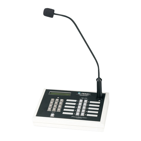
Page 11: Station Ten
2.4. Station Ten ™ Desktop Paging Station Station Ten ª is a ten button desktop station that includes an electret condenser microphone. Each of the ten zone presets are defined and programmed by the PageMatrix software. In addition, a 12 button Òtelephone styleÓ... - Page 12 Station Ten Operation LED color indicates status of each of the ten zone presets. Green indicates the zone is available and not in use by another station. Red indicates the zone is in use. When the Push To Talk button is pressed, the selected zone preset LED turns orange to confirm that it is active.
-
Page 13: Typical Pagematrix Connection
2 . 4 . T y p i c a l P a g e M a t r i x C o n n e c t i o n MediaMatrix BoB Cable Up to 16 Stations of any combination CAT 5 STANDARD ÒData TypeÓ... -
Page 14: Software Description
C. This is a self-extracting zip file that will ask you for a directory to place the unzip files. These files MUST go in the Devices directory in your MediaMatrix root directory (c:\peavey\devices\standard\paging) If your root directory is different from the default, enter the proper root directory followed by Òdevices\standard\pagingÓ. -
Page 15: Launching
3.2.1. Launching PageMatrix Windows 95: 1. Under the Start menu, select Programs. 2. Find the PageMatrix directory and select it. 3. Locate PageMatrix , and select it. Windows 3.1: 1. Find the PageMatrix Program Group within the Program Manager 2. Doulbe click the group, then double click the PageMatrix Icon. Note: For systems that are not pre-loaded with PageMatrix, the MediaMatrix Program Launcher can be used. -
Page 16: Menu Overview
3.3. PAGEMATRIX APPLICATION MENU BAR OVERVIEW 3.3.1 File Menu Print Not active at this time. Print Preview Not active at this time. Print SetupÉ Not active at this time. Download ConfigurationÉ This option allows you to send your configuration settings to the PageMatrix controller. Since this will replace the current configuration loaded into the controller, a ÒDo you wish to continue?Ó... -
Page 17: Edit Menu
3.3.2. Edit Menu Insert Station Creates a new paging station that is available for editing. It is placed in the list before the currently selected station. Selecting this option opens the ÒNew Station PropertiesÓ dialog and allows the following edits: Station Name: Up to 16 characters. -
Page 18: Tools Menu
3.3.3. Tools Menu/Options Max Number of Zones Use this parameter to set the maximum number of zones used in your system. Communications Used to set the upload/download port. In addition to COM 1-4, an Offline Programming option is available when working remotely. 3.3.4. -
Page 19: Pagematrix Operation
4 . 0 . T y p i c a l P a g e M a t r i x O p e r a t i o n 4.1. Overview 4.1.1. The components PageMatrix / MediaMatrix paging systems consist of five primary components: At least one PageMatrix paging station connected to the PageMatrix controller via the proper category five cabling PageMatrix controller with the appropriate configuration file loaded... -
Page 20: The Mediamatrix System And Pasha
3: To interpret the proprietary control data from the paging stations and convert it to standard serial strings which can be forwarded to MediaMatrix. Microphone signals from the paging stations are not acted upon by the PageMatrix Controller, but are simply passed through the box as received. Any switching or routing is done within MediaMatrix. -
Page 21: Troubleshooting
Basic OperationÐHere we go... 1. Find the appropriate .txt file for the device you wish to use. 2. Rename this file to pasha.ini and place in the Peavey directory (mediamatrix\views). Note: If you wish to keep the original pasha.ini file, just rename it. -
Page 22: Appendix
5 . A P P E N D I X 5.1. Factory Support Peavey provides customer support and service direct from the factory. If you need further assistance or information, donÕt hesitate to call us. You can reach us 8 a.m. - 5 p.m. CST at (800) 543-2991 or (601) 483-5376. -
Page 23: Using The Mediamatrix Program Launcher
5.2. Using the MediaMatrix Program Launcher The Program Launcher is found in the Device/Miscellaneous Menu. It is used to make it easy to open another Windows application while you are using MediaMatrix. You can label the Program Launcher block and include it in any window of a MediaMatrix design. The Program Launcher device ª... -
Page 24: Station Four-W Wiring Diagrams
5 . 3 . S t a t i o n 4 - W W i r i n g D i a g r a m Cat 5 Plug 4-Pin Connector Cat 5 Plug 3-Pin Connector CAT 5 8 7 6 5 4 3 2 1 NOTE: This is not a network connection. -
Page 25: 5-Pin Aux Mic Input Wiring Diagram
5.4. 5-Pin Wiring Diagram Audio + Audio - Mic Switch... -
Page 26: Configuring The Pagematrix Controller
5.5. Configuring the PageMatrix Controller As mentioned previously, the PageMatrix controller supports up to sixteen paging stations simultaneously. In larger applications where multiple controllers are necessary, the various PageMatrix units must be configured for IDs beyond the default 1-16 setting. This is accomplished by changing the DIP switch settings inside the unit. -
Page 27: Specifications
5.6. Specifications P o w e r R e q u i r e m e n t s : D o m e s t i c : 1 2 0 V A C ~ , 6 0 H z , 5 0 W E x p o r t : 1 0 0 V A C ~ , 5 0 / 6 0 H z , 5 0 W 2 3 0 V A C ~ , 5 0 / 6 0 H z , 5 0 W I n c l u d e d A c c e s s o r i e s :... - Page 28 1. Introducción Lo felicitamos por su sabia elecci—n del sistema PageMatrix intercomunicaci—n actuales y futuros. Utilizado en conjunto con nuestro aclamado sistema de audio digital MediaMatrix ¨ para todas las aplicaciones de intercomunicaci—n profesionales. MediaMatrix sirve como unidad central de procesamiento al proyecto en su totalidad, control‡ndolo, desde el encaminamiento de la se–al, hasta la administraci—n integral del sistema de intercomunicaci—n.
- Page 29 El controlador dispone de una entrada para el funcionamiento con alimentaci—n a distancia de +24 VCC. Se utilizan conectores tipo Phoenix para llevar la se–al de intercomunicaci—n de audio a las cajas distribuidoras BoB. El controlador sustenta hasta cuatro sistemas MediaMatrix. En el panel frontal del controlador hay 16 LED de estaci—n, que indican el estado de cada una de ellas.
- Page 30 Panel posterior Puerto de programas (RS-232): Acepta los datos del software PageMatrix desde el puerto serie (Com 1 o Com 2) de la computadora central. Puertos de datos (4 enchufes RS-232 hembra): Permiten la conexi—n y el control de hasta cuatro sistemas MediaMatrix.
- Page 31 2.2. Estación de intercomunicación de pared Station Four-W Es una estaci—n de intercomunicaci—n que incluye un micr—fono port‡til (de 5 terminales) con un pulsador para hablar. Cada una de las preprogramaciones de las cuatro zonas de intercomunicaci—n se define y programa con el software PageMatrix. Panel frontal Botones de zonas preprogramadas con LED indicadores (4): Utilizados para seleccionar cualquiera de las cuatro zonas preprogramadas.
- Page 32 Operación de la estación Station Four-W El color del LED indica el estado de cada una de las zonas preprogramadas. El color verde indica que la zona est‡ disponible y que no est‡ siendo utilizada por otra estaci—n. El color rojo indica que la zona est‡ en uso. Cuando se oprime el bot—n para hablar, el LED indicador de la zona preprogramada se ilumina de color naranja, para confirmar que est‡...
- Page 33 2.3. Estación de intercomunicación de mesa Station Four Es una estaci—n de cuatro botones, que incluye un micr—fono de condensador de electreto. Cada una de las preprogramaciones de las cuatro zonas de intercomunicaci—n se define y programa con el software PageMatrix. Panel posterior Entrada de micr—fono de 5 terminales: Se usa para conectar un micr—fono remoto con pulsador para hablar.
- Page 34 Las zonas preprogramadas se pueden rotular en las casillas color blanco correspondientes. Si todos los LED indicadores destellan con luz roja al encender el sistema, significa que la estaci—n no ha sido programada. Si todos los LED indicadores destellan con luz verde al encender el sistema, significa que la estaci—n ha sido programada.
- Page 35 Volumen de micr—fono: Ajuste embutido de ganancia del micr—fono. Panel posterior Entrada de micr—fono auxiliar de 5 terminales: Se usa para conectar un micr—fono remoto con pulsador para hablar. Consulte el diagrama de cableado del ApŽndice 5.4. El micr—fono auxiliar se encamina autom‡ticamente a la zona preprogramada uno.
- Page 36 referimos a las asignaciones a los botones como Òzonas preprogramadasÓ, porque esas programaciones se establecen inicialmente y luego se cargan en el controlador PageMatrix donde se activan. Acerca de la prioridad Con el sistema PageMatrix, no hay par‡metros de prioridad inherentes a cada estaci—n f’sica. Cualquier micr—fono se puede utilizar en cualquier momento y el LED indicador ÒocupadoÓ...
- Page 37 Esos archivos pueden estar en cualquier posici—n en su disco r’gido, pero se recomienda que los instale en el subdirectorio View del directorio ra’z del sistema (c:\peavey\views). D. Una vez que confirme el directorio, haga clic en Unzip (descomprimir).
- Page 38 Estos archivos DEBEN ESTAR en el directorio Devices (dispositivos) del directorio ra’z de su sistema MediaMatrix (c:\peavey\devices\standard\paging). Si su directorio ra’z es diferente al asignado por defecto, ingrese el directorio ra’z apropiado seguido por Òdevices\standard\pagingÓ. D. Una vez que confirme el directorio, haga clic en Unzip (descomprimir).
- Page 39 Para incluir sus estaciones de hardware en la programaci—n, en el menœ Edit (edici—n,) utilice ÒInsert StationÓ (insertar estaci—n) o ÒAdd StationÓ (agregar estaci—n), segœn sea necesario. DespuŽs de configurar inicialmente la aplicaci—n PageMatrix, el diagrama de la izquierda muestra una columna con todas las estaciones de intercomunicaci—n conectadas.
- Page 40 3.3.2. Menú Edit (edición) Insert Station (insertar estaci—n) Crea una estaci—n de intercomunicaci—n nueva que queda disponible para edici—n. Se coloca en la lista precediendo a la estaci—n actualmente seleccionada. Al seleccionar esta opci—n se abre el cuadro de di‡logo ÒNew Station PropertiesÓ (propiedades de la estaci—n nueva), que permite efectuar las siguientes ediciones: Station Name (nombre de la estaci—n): Hasta 16 caracteres.
- Page 41 3.3.3. Menœ de herramientas/opciones Max Number of Zones (cantidad m‡xima de zonas) Utilice este par‡metro para configurar la cantidad de estaciones utilizadas en su sistema. Communications (comunicaciones) Utilizado para configurar el env’o/carga de un puerto. Adem‡s de las opciones COM 1 a-4, para trabajar a distancia hay disponible una opci—n Offline Programming (programaci—n fuera de l’nea).
- Page 42 4.0. Operación típica del sistema PageMatrix 4.1. Reseña 4.1.1. Componentes Los sistemas de intercomunicaci—n PageMatrix/MediaMatrix consisten en cinco componentes primarios: Una estaci—n de intercomunicaci—n PageMatrix como m’nimo, conectada al controlador PageMatrix mediante el cableado categor’a cinco apropiado Un controlador PageMatrix con el archivo de configuraci—n apropiado cargado El software de aplicaci—n del sistema PageMatrix Un sistema de audio MediaMatrix que ejecute el archivo PASHA Un archivo PASHA.ini configurado para el archivo de visualizaci—n compilado...
- Page 43 3: Interpretar los datos de control patentados de las estaciones de intercomunicaci—n y convertirlos en cadenas serie est‡ndar, que se pueden dirigir al sistema MediaMatrix. El controlador PageMatrix no actœa sobre las se–ales de las estaciones de intercomunicaci—n, s—lo pasan a travŽs de la caja como se reciben. Toda conmutaci—n o encaminamiento se efectœa dentro del sistema MediaMatrix.
- Page 44 5. Apéndice 5.1. Apoyo técnico de la fábrica Peavey provee apoyo al cliente y servicio tŽcnico directo de la f‡brica. Si usted necesita asistencia o informaci—n m‡s amplia, no dude en llamarnos. Puede tomar contacto con nosotros entre las 8 a.m. y las 5 p.m. (0800 a 1700) horas, hora central (CST) de los Estados Unidos, en los telŽfonos (800) 543-2991 o (601) 483-5376.
- Page 45 Tenga a bien dirigir su correo electr—nico con su archivo de visualizaci—n agregado a: George Douglas, National Sales Manager (Gerente Nacional de Ventas): george@peavey.com Ken Valentine, Central District Manager (Gerente del Distrito Central): ken@peavey.com Will Roland, Western District Manager (Gerente del Distrito Oeste): will@peavey.com...
- Page 46 5.2. Utilización del MediaMatrix Program Launcher (iniciador de programas del sistema MediaMatrix) El Program Launcher (iniciador de programas), se encuentra en el menœ Device/Miscellaneous (dispositivos/varios). Se lo utiliza para simplificar la apertura de otra aplicaci—n Windows, mientras se est‡ usando el sistema MediaMatrix. Usted puede asignar nombre al bloque del Program Launcher e incluirlo en cualquier ventana de un dise–o MediaMatrix.
- Page 47 5 . 3 . S t a t i o n 4 - W W i r i n g D i a g r a m Cat 5 Plug 4-Pin Connector Cat 5 Plug 3-Pin Connector CAT 5 8 7 6 5 4 3 2 1 NOTE: This is not a network connection.
- Page 48 5 . 4 . 5 - P i n M i c W i r i n g D i a g r a m Audio + Audio - Mic Switch...
- Page 49 5.5. Configuración del controlador del sistema PageMatrix Como se mencion— previamente, el controlador PageMatrix soporta simult‡neamente hasta 16 estaciones de intercomunicaci—n. En las aplicaciones m‡s grandes, en las que son necesarios varios controladores, las diferentes unidades del sistema PageMatrix se deben configurar con identidades m‡s all‡...
- Page 50 5.6. Especificaciones Requisitos de alimentaci—n: Modelos para los EE.UU.: 120 VCA~, 60 Hz, 50 W Modelos para exportaci—n: 100 VCA~, 50/60 Hz, 50 W 230 VCA~, 50/60 Hz, 50 W Accesorios que se incluyen: Cable de alimentaci—n aprobado por IEC (4) Conectores tipo Phoenix de 12 posiciones (1) Conectores tipo Phoenix de 3 posiciones Dimensiones y peso:...
- Page 51 INSTRUCCIONES DE SEGURIDAD IMPORTANTES ADVERTENCIA: Al utilizar productos elŽctricos se deben respetar las precauciones b‡sicas, que incluyen las siguientes: Lea estas instrucciones. Conserve estas instrucciones. Preste atenci—n a todas las advertencias. Respete todas las instrucciones. No utilice este aparato cerca del agua. Por ejemplo, cerca o dentro de ba–eras, piscinas, lavaderos, s—tanos hœmedos, etc. Limpie el aparato solamente con un trapo hœmedo.
- Page 52 1. Introduction FŽlicitations pour avoir eu la sagesse de choisir le syst•me PageMatrix tŽlŽappel actuels et futurs. UtilisŽ en conjonction avec notre syst•me audio numŽrique MediaMatrix universellement acclamŽ, le PageMatrix constitue une approche intŽgrŽe et souple pour toutes les applications de tŽlŽappel sŽrieuses. Le MediaMatrix sert de processeur central pour lÕensemble du projet, contr™lant la totalitŽ...
- Page 53 Quatre syst•mes MediaMatrix peuvent •tre raccordŽs au contr™leur. Le panneau avant du contr™leur est dotŽ de 16 DEL indiquant lÕŽtat des postes. 2. Description des composants matériels 2.1 Contrôleur PageMatrix Le contr™leur PageMatrix constitue le coeur du syst•me. Il est reliŽ par un port sŽrie RS-232 au ch‰ssis MediaMatrix sur lequel tournent les logiciels MediaMatrix et PageMatrix.
- Page 54 Panneau arri•re 6. Port de programmation (RS-232): accepte les donnŽes du logiciel PageMatrix transmises par le port sŽrie de lÕordinateur h™te (Com 1 ou Com 2). 7. Ports de donnŽes de contr™le (4 jacks RS-232): permettent de brancher et de contr™ler jusquÕˆ...
- Page 55 2.2. Poste de téléappel à montage mural Station Four-W Le Station Four ª -W est un poste ˆ montage mural ˆ quatre touches comprenant un microphone ˆ main dotŽ dÕun alternat. Chacune des quatre prŽsŽlections de zone est dŽfinie et programmŽe par le logiciel PageMatrix.
- Page 56 Fonctionnement du poste Station Four-W La couleur des DEL indique lÕŽtat de chacune des zones prŽsŽlectionnŽes. La couleur verte indique que la zone nÕest pas utilisŽe par un autre poste et quÕelle est donc libre. La couleur rouge indique que la zone est occupŽe. Lorsque le bouton dÕalternat est enfoncŽ, la DEL de la zone sŽlectionnŽe devient orange, indiquant quÕelle est active.
-
Page 57: Station Four ª
2.3. Poste de téléappel de bureau Station Four Le Station Four ª est un poste de tŽlŽappel de bureau ˆ quatre touches comprenant un microphone ˆ condensateur Žlectret. Chacune des quatre prŽsŽlections de zone est dŽfinie et programmŽe par le logiciel PageMatrix. Panneau arri•re EntrŽe microphone auxiliaire ˆ... -
Page 58: Station Ten ª
Si toutes les DEL clignotent en vert lors de la mise sous tension, cela signifie que le poste a ŽtŽ programmŽ. LÕentrŽe de microphone auxiliaire (panneau arri•re) est toujours acheminŽe ˆ la prŽsŽlection de zone 1. 2.4. Poste de téléappel de bureau Station Ten Le Station Ten ª... - Page 59 Panneau arri•re EntrŽe microphone auxiliaire ˆ 5 broches: DestinŽe au branchement dÕun microphone ˆ distance dotŽ dÕun alternat. Voir le schŽma de c‰blage ˆ lÕannexe 5.4. Le microphone auxiliaire est automatiquement acheminŽ ˆ la prŽsŽlection de zone 1. Connecteur RJ45: Pour le branchement du contr™leur PageMatrix.
- Page 60 est occupŽe par un autre poste. Toutefois, des niveaux de prioritŽ complexes peuvent •tre configurŽs et intŽgrŽs au syst•me. 2 . 4 . T y p i c a l P a g e M a t r i x C o n n e c t i o n BoB Cable Up to 16 Stations of any combination CAT 5 STANDARD ÒData TypeÓ...
- Page 61 C. Ce fichier zip ˆ extraction automatique demande le nom du rŽpertoire o• placer les fichiers dŽcompressŽs. Ces fichiers DOIVENT •tre installŽs dans le sous-rŽpertoire Devices (utilitaires) du rŽpertoire racine MediaMatrix (c:\peavey\devices\standard\paging). Si votre 3.1. Matériel requis Minimum: PC 486DX-100 ou plus rapide avec Windows version 3.1 / 95 / NT4 ou plus rŽcente,...
- Page 62 rŽpertoire racine est diffŽrent de celui spŽcifiŽ en usine, entrez-le suivi de Òdevices\ standard\pagingÓ. D. Une fois le rŽpertoire confirmŽ, cliquez sur Unzip (dŽcompresser). E. Lorsque lÕinstallation est terminŽe, cliquez sur Close (fermer). 3.2.1. Lancement de PageMatrix Windows 95: 1. Dans le menu Start (DŽmarrer) sŽlectionnez Programs (Programmes). 2.
- Page 63 Noms des prŽsŽlections de zone avec le poste Station Ten Le poste Station Ten est dotŽ dÕun affichage 20 x 2 permettant de voir les prŽsŽlections de zone. Celles-ci sont nommŽes dans lÕapplication PageMatrix. LorsquÕun poste ˆ 10 touches est insŽrŽ (option Edit/Insert Station) lÕoption de texte appara”t en haut de lÕŽcran ACL.
- Page 64 3.3.2. Menu Edit (Ždition) Insert Station (InsŽrer Poste) Cette option permet de crŽer un nouveau poste de tŽlŽappel pouvant •tre modifiŽ. Elle se trouve dans la liste avant le poste actuellement sŽlectionnŽ. Choisissez-la pour ouvrir la bo”te de dialogue ÒNew Station PropertiesÓ (propriŽtŽs du nouveau poste) et apporter les changements suivants : Station Name (nom de poste): jusquÕˆ...
-
Page 65: About Pagematrix
3.3.3. Menu Tools/Options (outils/options) View Toolbar (Afficher Barre DÕoutils) Max Number of Zones (Nombre Maximum De Zones) Ce param•tre dŽfinit le nombre maximum de zones utilisŽes avec le syst•me. Communications Permet de configurer le port de tŽlŽchargement (ports COM 1 ˆ 4). Une option de programmation hors ligne est Žgalement disponible pour lÕopŽration ˆ... - Page 66 4.0. Fonctionnement de PageMatrix 4.1. Généralités 4.1.1. Composants Les syst•mes PageMatrix / MediaMatrix sont constituŽs de cinq composants principaux : Au moins un poste de tŽlŽappel PageMatrix reliŽ au contr™leur par un c‰ble de catŽgorie cinq adŽquat Un contr™leur PageMatrix dans lequel le fichier de configuration appropriŽ est chargŽ Le logiciel dÕapplication PageMatrix Un syst•me audio MediaMatrix pilotŽ...
- Page 67 2: Il achemine les signaux analogiques de microphone des postes de tŽlŽappel aux entrŽes des bo”tes de distribution du contr™leur MediaMatrix. 3: Il analyse les donnŽes de contr™le de chaque poste de tŽlŽappel et les convertit en cha”nes de donnŽes standard pouvant •tre transmises au contr™leur MediaMatrix. Les signaux de microphone des postes de tŽlŽappel ne sont pas traitŽs par le contr™leur PageMatrix mais le traversent simplement tels quÕils sont re•us.
- Page 68 Utilisation de base Ð Tout dÕabord... 1. Trouvez le fichier .txt pour le syst•me que vous dŽsirez utiliser. 2. Donnez ce fichier le nom Pasha.ini et placez-le dans le rŽpertoire Peavey (mediamatrix\views). Remarque : Pour conserver le fichier pasha.ini existant, il suffit de le renommer.
- Page 69 ˆ lÕadresse suivante : Peavey Electronics Corp. ¥ MediaMatrix Support Group ¥ 711 A St. ¥ Meridian, MS 39301 ¥ ƒtats-Unis Vous pouvez Žgalement obtenir, 24 heures sur 24 et sept jours sur sept, des conseils utiles, fiches techniques, rŽponses aux questions souvent posŽes, notes dÕapplications et autres informations...
- Page 70 5.2 Utilisation du lanceur de programme MediaMatrix Le lanceur de programme se trouve dans le menu Device/Miscellaneous (syst•me/divers). Il permet dÕouvrir facilement une autre application Windows pendant lÕutilisation de MediaMatrix. Le bloc de lanceur de programme peut •tre ŽtiquetŽ et inclus dans nÕimporte quelle fen•tre dÕun programme ª...
- Page 71 5 . 3 . S t a t i o n 4 - W W i r i n g D i a g r a m Cat 5 Plug 4-Pin Connector Cat 5 Plug 3-Pin Connector CAT 5 8 7 6 5 4 3 2 1 NOTE: This is not a network connection.
- Page 72 5.4. 5-Pin Wiring Diagram Audio + Audio - Mic Switch...
- Page 73 5.5. Configuration du contr™leur PageMatrix Comme il lÕa ŽtŽ mentionnŽ plus haut, le contr™leur PageMatrix peut commander jusquÕˆ 16 postes simultanŽment. Dans les applications plus Žtendues o• il est nŽcessaire dÕutiliser plusieurs contr™leurs, les codes dÕidentification des diffŽrentes unitŽs PageMatrix peuvent •tre configurŽs au-delˆ...
-
Page 74: Fiche Technique
5.6. Fiche technique Alimentation : ƒtats-Unis: 120 V c.a.~, 60 Hz, 50 W Exportation: 100 V c.a~, 50/60 Hz, 50 W 230 V c.a.~, 50/60 Hz, 50 W Accessoires inclus: Cordon dÕalimentation CEI (4) connecteurs Phoenix 12 positions (1) connecteur Phoenix 3 positions Dimensions et poids: 3,5 po H x 19 po L x 11,69 po P (8,9 x 48,3 x 29,7 cm) (sans les connecteurs) - Page 75 NOTE IMPORTANTE CONCERNANT LA SECURITE ATTENTION: Lors de lÕutilisation de appareils Žlectriques, certaines mesures de sŽcuritŽ doivent •tre respectŽes: Lisez toutes les instructions. Conservez ces instructions. Tenez compte de tous les avertissements. Suivez prŽcisemment les instructions. NÕutilisez pas lÕappareil ˆ proximitŽ de lÕeau. Par exemple prŽs dÕun bain, dÕune piscine, dÕun Žvier, ou dans un sous-sol humide. Nettoyez avec un chiffon sec uniquement.
- Page 76 1. Einleitung Wir beglŸckwŸnschen Sie zu Ihrer klugen Entscheidung, fŸr Ihren jetzigen und kŸnftigen Rufanlagen-Bedarf das PageMatrix populŠren digitalen Audiosystem MediaMatrix Gesamtlšsung fŸr Rufanlagen mit professionellem Anspruch. MediaMatrix dient als Verarbeitungszentrale fŸr eine vollstŠndige Anlage und steuert alle AblŠufe Ð von der Signallenkung bis zur Rufanlagenverwaltung. Das PageMatrix-System umfa§t mehrere Rufstationen, die sich problemlos je nach Ruf- und Zonenerfordernissen praktisch beliebig konfigurieren lassen.
- Page 77 2. Beschreibung der Hardware 2.1 Der PageMatrix-Controller Der PageMatrix-Controller ist das HerzstŸck des Systems. Er wird Ÿber einen seriellen RS-232- Anschlu§ am MediaMatrix-Computer angeschlossen, in dem MediaMatrix und das PageMatrix- Programm laufen. Ein PageMatrix-Controller kann bis zu vier separate MediaMatrix-Systeme steuern (er verfŸgt Ÿber vier SteuerungsanschlŸsse).
- Page 78 RŸckwand Programmanschlu§ (RS-232): Dient zum Empfang der PageMatrix-Programmdaten vom seriellen Anschlu§ des Host-Computers (COM 1 oder COM 2). Steuerungsdaten-AnschlŸsse (4 RS-232-Buchsen): Dienen zum Anschlu§ bzw. zur Steuerung von bis zu vier MediaMatrix-Systemen. StationseingŠnge (16 RJ45-Buchsen): Jede Station wird mit einem CAT-5-Kabel an einem der sechzehn StationseingŠnge angeschlossen.
- Page 79 2.2. Rufstation Station Four-W™ zur Wandmontage Die Station Four ª -W ist eine fŸr die Wandmontage vorgesehene Station mit vier Tasten und einem Handmikrofon mit Drucktastenaktivierung. Die vier Zonenvoreinstellungen werden Ÿber die PageMatrix-Software definiert und programmiert. Frontplatte 4 Zonentasten mit Leuchtdioden: Dienen zum AnwŠhlen einer der vier voreingestellten Zonen.
- Page 80 Betrieb der Station Four-W Die Leuchtdiodenfarbe gibt den Status der jeweiligen Voreinstellzone wieder: GrŸn bedeutet, da§ die Zone frei ist, d.h. nicht von einer anderen Station gerufen wird. Rot bedeutet, da§ die Zone belegt ist. DrŸckt man auf die Sprechtaste des Mikrofons (ãTalkÒ), wird die gewŠhlte Zonentaste orange und bestŠtigt damit die Aktivierung.
- Page 81 2.3. Tisch-Rufstation Station Four Die Station Four ª ist eine Tischstation mit vier Tasten und einem Elektret-Kondensatormikrofon. Die Zonenvoreinstellungen der vier Tasten werden Ÿber die PageMatrix-Software definiert und programmiert. RŸckwand FŸnfpoliger Zusatzmikrofoneingang (Aux Mic) Zum Anschlu§ eines separaten Mikrofons mit Tastenaktivierung. Siehe Schaltplan, Anhang 5.4.
- Page 82 2.4. Tisch-Rufstation Station Ten™ Die Station Ten ª ist eine Tischstation mit zehn Tasten und einem Elektret-Kondensatormikrofon. Die zehn Zonenvoreinstellungen werden Ÿber die PageMatrix-Software definiert und programmiert. Au§erdem ist sie mit einer telefonŠhnlichen Tastatur mit 12 Tasten sowie einem 20 mal 2 Elementen gro§en LCD-Display ausgestattet, mit denen bis zu 99 ãvirtuelleÒ...
- Page 83 Betrieb der Station Ten Die Leuchtdiodenfarbe gibt den Status der jeweiligen Voreinstellzone wieder: GrŸn bedeutet, da§ die Zone frei ist, d.h. nicht von einer anderen Station gerufen wird. Rot bedeutet, da§ die Zone belegt ist. DrŸckt man auf die Sprechtaste, wird die gewŠhlte Zonentaste orange und bestŠtigt damit die Aktivierung.
- Page 84 2 . 4 . T y p i c a l P a g e M a t r i x C o n n e c t i o n BoB Cable Up to 16 Stations of any combination CAT 5 STANDARD ÒData TypeÓ...
- Page 85 Dateien abgelegt werden kšnnen. Dieses Verzeichnis ist zwar beliebig wŠhlbar, jedoch empfehlen wir, die Dateien in dem Verzeichnis ãViewsÒ im MediaMatrix-Stammverzeichnis abzulegen (c:\peavey\views). D. BestŠtigen Sie das Verzeichnis, und klicken Sie auf ãUnzipÒ. E. Klicken Sie nach Abschlu§ der Installation auf ãCloseÒ.
- Page 86 Dateien abgelegt werden kšnnen. Diese Dateien M†SSEN im Verzeichnis ãDevicesÒ des MediaMatrix-Stammverzeichnisses gespeichert werden (c:\peavey\devices\standard\paging). Wenn das Stammverzeichnis nicht den vorgegebenen Namen hat, geben Sie bitte den entsprechenden Namen ein, gefolgt von ãdevices\standard\pagingÒ. D. BestŠtigen Sie das Verzeichnis, und klicken Sie auf ãUnzipÒ.
- Page 87 links auf dem Bildschirm eine Spalte zu sehen, in der alle angeschlossenen Rufstationen aufgelistet sind. Rechts oben befindet sich eine Matrix-Liste der Zonen, darunter die Spalten mit den durchnumerierten Tasten. WŠhlen Sie die Station aus, die Sie zuerst programmieren mšchten, und aktivieren Sie dann mit der Maus Zonen fŸr jede Ruftaste.
- Page 88 3.3.2. MenŸ ãEditÒ (Bearbeiten) Insert Station (Station einfŸgen) Dient zum Erstellen einer neuen Rufstation, die dann bearbeitet werden kann. Sie erscheint auf der Liste vor der derzeit gewŠhlten Station. WŠhlt man diese Option, erscheint das Dialogfeld ãNew Station PropertiesÒ, das folgende BearbeitungsvorgŠnge ermšglicht: Station Name: bis zu 16 Zeichen.
- Page 89 3.3.3. MenŸ ãTools/OptionsÒ Max Number of Zones (max. Anzahl von Zonen) Mit diesem Parameter wird die maximale Anzahl der Zonen in dem System festgelegt. Communications (Kommunikation) Dient zum Einstellen des Fernladeanschlusses. ZusŠtzlich zu den COM-Ports 1-4 steht bei der abgesetzten Bedienung eine Offline-Programmieroption zur VerfŸgung. 3.3.4.
- Page 90 4.0. Das Funktionsschema von PageMatrix 4.1. Überblick 4.1.1. Die Komponenten PageMatrix/MediaMatrix-Rufsysteme bestehen aus fŸnf Hauptkomponenten: Mindestens einer PageMatrix-Rufstation, die mit den richtigen CAT-5-Kabeln am PageMatrix-Cotroller angeschlossen ist. Dem PageMatrix-Controller, in den die benštigte Konfigurationsdatei geladen wurde. Der PageMatrix-Software Einem MediaMatrix-Audiosystem, in dem PASHA lŠuft. Einer Datei namens PASHA.ini, die fŸr die Ansichtsdatei (View File) kompiliert ist.
- Page 91 3: Die Interpretation der proprietŠren, von den Rufstationen gesendeten Steuerungsdaten und deren Umwandlung in serielle Standardstrings, die an MediaMatrix weitergeleitet werden kšnnen. Der PageMatrix-Controller verarbeitet die Mikrofonsignale von den Rufstationen in keiner Weise, sondern leitet sie sofort und unverŠndert weiter. Alle Schalt- und LeitvorgŠnge finden innerhalb von MediaMatrix statt.
- Page 92 Inbetriebnahme Ð So wirdÕs gemachtÉ 1. Suchen Sie die *.txt-Datei zu der Einheit, die Sie benutzen mšchten. 2. Benennen Sie diese Datei in ãpasha.iniÒ um, und speichern Sie sie im Peavey- Verzeichnis ãmediamatrix\viewsÒ. Hinweis: Wenn Sie die ursprŸngliche ãpasha.iniÒ-Datei behalten mšchten, geben Sie ihr einfach einen anderen Namen.
- Page 93 Stunden frŸher als MEZ) unter 001 601 483 5376. Die Anschrift fŸr alle Korrespondenzen sowie zum Anfordern von LektŸre zu aktuellen und neuen Produkten lautet: Peavey Electronics Corp. ¥ MediaMatrix Support Group ¥ 711 A St. ¥ Meridian, MS 39301 ¥ USA Hilfreiche Tips, technische Daten, Antworten zu hŠufig gestellten Fragen (FAQÕs), Beispieldateien, ApplikationsbroschŸren und Informationen zu weiteren Produkten von Peavey Architectural...
- Page 94 5.2. Der MediaMatrix Program Launcher Der Program Launcher (Programmstarter) ist im MenŸ ãDevice/MiscellaneousÒ zu finden. Er erleichtert das …ffnen anderer Windows-Programme, wŠhrend mit MediaMatrix gearbeitet wird. Den Program Launcher-Block kšnnen Sie beschriften und in jedes beliebige Fenster eines MediaMatrix- Designs aufnehmen. Der Program Launcher startet entweder ein anderes Windowsª-Programm, oder er schaltet zu diesem Programm um, wenn es bereits lŠuft.
- Page 95 5 . 3 . S t a t i o n 4 - W W i r i n g D i a g r a m Cat 5 Plug 4-Pin Connector Cat 5 Plug 3-Pin Connector CAT 5 8 7 6 5 4 3 2 1 NOTE: This is not a network connection.
- Page 96 5.4. 5-Pin Wiring Diagram Audio + Audio - Mic Switch...
- Page 97 5.5. Konfigurieren des PageMatrix-Controllers Wie bereits erwŠhnt, unterstŸtzt der PageMatrix-Controller bis zu sechzehn Rufstationen gleichzeitig. Bei umfangreichen Systemen mit mehreren Controllern mŸssen die einzelnen PageMatrix-Einheiten Kennungen (IDÕs) erhalten, die Ÿber die Standardeinstellung von 1 bis 16 hinausgehen. Dies geschieht durch €ndern der DIP-Schalterstellungen in der jeweiligen Einheit. 1.
-
Page 98: Technische Daten
5.6. Technische Daten Anschlu§werte USA: 120 V~, 60 Hz, 50 W Export: 100 V~, 50/60 Hz, 50 W 230 V~, 50/60 Hz, 50 W Zubehšr im Lieferumfang: IEC-Netzkabel 4 Phoenix-Stecker mit 12 Positionen 1 Phoenix-Stecker mit 3 Positionen Abmessungen und Gewicht 89 mm x 483 mm x 297 mm (H x B x T) (Stecker nicht inbegriffen) 6214 g... - Page 99 WARNUNG: Beim Einsatz elektrischer GerŠte sollten stets nachfolgend genannte grundlegende Sicherheitsrichtlinien beachtet werden: Lesen Sie diese Richtlinien. Bewahren Sie diese Richtlinien stehts griffbereit auf. Beachten Sie sŠmtliche Richtlinien. Befolgen Sie alle Anweisungen. Benutzen Sie das GerŠt nicht in unmittelbarer WassernŠhe (z. B. Badewanne, Waschbecken, Swimming-Pool, etc.). Nur mit einem feuchten oder klammen Tuch reinigen.
- Page 100 NOTES:...
- Page 101 NOTES:...
-
Page 102: Important Safety Instructions
WARNING: When using electric products, basic cautions should always be followed, including the following: Read these instructions. Keep these instructions. Heed all warnings. Follow all instructions. Do not use this apparatus near water. For example, near or in a bathtub, swimming pool, sink, wet basement, etc. Clean only with a damp cloth. -
Page 103: Specifications
What Peavey Will Do We will repair or replace (at Peavey's discretion) products covered by warranty at no charge for labor or materials. If the product or component must be shipped to Peavey for warranty service, the consumer must pay initial shipping charges. If the repairs are covered by warranty, Peavey will pay the return shipping charges. - Page 104 Features and specifications subject to change without notice. Peavey Electronics Corporations ¥ 711 A Street ¥ Meridian, MS 39301 ¥ U.S.A. (601) 483-5367 ¥ Fax (601) 486-1678 ¥ www.peavey.com ©1999 Printed in U.S.A. 1/99 80304504...