Table of Contents
Advertisement
Quick Links
Download this manual
See also:
User Manual
Advertisement
Table of Contents

Related Manuals for Acer ASPIRE 7745


Summary of Contents for Acer ASPIRE 7745
-
Page 1: Aspire 7745 Series
Aspire 7745 Series Service Guide Service guide files and updates are available on the ACER/CSD web; for more information, please refer to http://csd.acer.com.tw PRINTED IN TAIWAN... -
Page 2: Revision History
Revision History Please refer to the table below for the updates made on this service guide. Date Chapter Updates... - Page 3 Copyright Copyright © 2010 by Acer Incorporated. All rights reserved. No part of this publication may be reproduced, transmitted, transcribed, stored in a retrieval system, or translated into any language or computer language, in any form or by any means, electronic, mechanical, magnetic, optical, chemical, manual or otherwise, without the prior written permission of Acer Incorporated.
-
Page 4: Conventions
Conventions The following conventions are used in this manual: SCREEN MESSAGES NOTE WARNING CAUTION IMPORTANT NOTE: This symbol where placed in the Service Guide designates a component that should be recycled according to the local regulations. Denotes actual messages that appear on screen. - Page 5 DIFFERENT part number code to those given in the FRU list of this printed Service Guide. You MUST use the list provided by your regional Acer office to order FRU parts for repair and service of customer machines.
-
Page 7: Table Of Contents
System Specifications Features ............1 System Block Diagram . - Page 8 Table of Contents Removing the Bluetooth Module ........72 Removing the USB Board .
- Page 9 Acer Aspire 7745G Series ........
- Page 10 Table of Contents...
-
Page 11: System Specifications
Dual-channel DDR3 SDRAM support: • Up to 4 GB of DDR3 1066 MHz memory, upgradable to 8 GB using two soDIMM modules Display • 17.3" HD+ 1600 x 900 pixel resolution, high-brightness (220-nit) Acer CineCrystal TFT LCD • 16:9 aspect ratio •... -
Page 12: Storage Subsystem
• WMV9 (VC-1) and H.264 (AVC) decoding ™ • HDMI (High-Definition Multimedia Interface) with HDCP (High-bandwidth Digital Content Protection) support Storage subsystem • One or two 160/250/320/500 GB or larger hard disk drive • Multi-in-1 card reader, supporting Secure Digital (MS), Memory Stick PRO Audio subsystem ®... -
Page 13: Privacy Control
Communication • Acer Video Conference, featuring:· • Acer Crystal Eye high-def webcam with 1280 x 1024 resolution • WLAN:· ® • Intel Centrino technology • Acer InviLink • Acer InviLink • Supporting Acer SignalUp • WPAN: Bluetooth • LAN: Gigabit Ethernet, Wake-on-LAN ready Privacy control •... - Page 14 • • Multimedia • Acer Arcade • NTI Media Maker • Gaming • Oberon GameZone Acer Edition (except US, Canada, Hong Kong, Korea) • WildTangent ™ , MMC, MS, MS PRO, xD) ® Player 10 ® ™ ® (except China, Hong Kong) ™...
-
Page 15: Optional Items
Communication and ISP ® • Microsoft Silverlight • Windows Live Writer) • Utilities and tools • Acer Accessory Store (Belgium, France, Germany, Italy, Netherlands, Spain, Sweden, UK only) • Acer Assist • Acer Identity Card • Acer Registration • Acer Updater ®... -
Page 16: System Block Diagram
System Block Diagram CLOCK GENERATOR SELGO: SLG8SP595V X'TAL 14.318MHz DDR III SO-DIMM 0 SO-DIMM 1 SO-DIMM 2 SO-DIMM 3 HDD (SATA) *2 ODD (SATA) USB Port x 4 USB 1, 3, 11, 12 (Debug) Bluetooth USB 4 USB 8 Relteak Audio CODEC Alcor ALC669X... -
Page 17: Notebook Tour
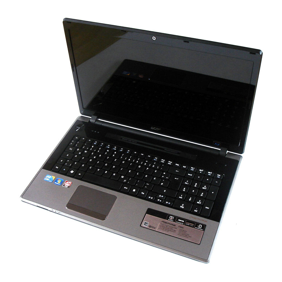
Notebook Tour This section provides an overview of the features and functions of the notebook. Top View Icon Microphone Display screen Chapter 1 Item Internal microphone for recording sound. Also called Liquid-Crystal Display (LCD), displays computer output (configuration may vary by model). Description... -
Page 18: Closed Front View
Icon HDD indicator Num Lock indicator Caps Lock indicator Power button/ Indicator Keyboard Touchpad Click buttons (left and right) Palmrest Acer PowerSmart P key Speaker Integrated webcam Closed Front View Icon Multi-in-1 card reader Power Battery Communication indicator Item Indicates when the hard disc drive is active. -
Page 19: Left View
Left View Icon Kensington lock slot Ventilation slots External display (VGA) port HDMI port USB 2.0 port Line-in jack Microphone jack Headphones/ speaker/line-out jack with S/PDIF support. Right View Chapter 1 Item Connects to a Kensington-compatible computer security lock. Note: Wrap the computer security lock cable around an immovable object such as a table or handle of a locked drawer. -
Page 20: Base View
Icon USB 2.0 port Optical drive Optical disk access indicator Optical drive eject button Emergency eject hole Ethernet (RJ-45) port DC-in jack Base View Icon Battery bay Battery lock Sub Woofer Memory compartment Item Connects to USB 2.0 devices (e.g., USB mouse, USB camera). -
Page 21: Indicators
Icon Hard disk bay - Main HDD bay - Secondary Battery release latch Indicators The computer has several easy-to-read status indicators. The power, battery and WiFi indicators are visible even when the computer cover is closed. Icon Function Power Battery Wireless LAN Num Lock Caps Lock... -
Page 22: Touchpad Basics
TouchPad Basics The following items show you how to use the TouchPad: • Move your finger across the TouchPad (1) to move the cursor. • Press the left (2) and right (3) buttons located beneath the TouchPad to perform selection and execution functions. -
Page 23: Using The Keyboard
Using the Keyboard Your computer has a close-to-full-sized keyboard and an embedded numeric keypad, separate cursor, lock, function and special keys. Lock Keys and embedded numeric keypad The keyboard has three lock keys which you can toggle on and off. Lock key Caps Lock When Caps Lock is on, all alphabetic characters typed are in uppercase. -
Page 24: Windows Keys
Windows Keys The keyboard has two keys that perform Windows-specific functions. Windows key Pressed alone, this key has the same effect as clicking on the Windows Start button; it launches the Start menu. It can also be used with other keys to provide a variety of functions: <... -
Page 25: Hot Keys
Hot Keys The computer employs hotkeys or key combinations to access most of the computer's controls like screen brightness and volume output. To activate hotkeys, press and hold the <Fn> key before pressing the other key in the hotkey combination. Hotkey Icon <Fn>... -
Page 26: Special Keys
Special Keys On models that support the Euro symbol and the US dollar sign, the symbols can be located at the upper- center and/or bottom-right of your keyboard. The Euro symbol Open a text editor or word processor. Hold <Alt Gr> and then press the <5> key at the upper-center of the keyboard. NOTE: Some fonts and software do not support the Euro symbol. -
Page 27: Hardware Specifications And Configurations
620 M 4 MB 720 M 6 MB 820 M 8 MB 3 MB Fan Speed (RPM) 2700 3000 3350 3650 3750 Core Package Acer P/N Voltage PGA988 KC.33001.DMP PGA988 KC.35001.DMP PGA988 KC.35K01.DMP PGA988 KC.37K01.DMP PGA988 KC.43001.DMP PGA988 35 W KC.45K01.DMP PGA988P KC.52001.DMP... - Page 28 Pixel size Image size Fan Speed (RPM) 2700 3000 3350 3650 Specification ACER AC7T_A10B AC7T Internal 17 103/104/107 Supports application keys for Windows 7 version AU6437-GBL -GR LQFP • Fully compatible with USB2.0 High Speed and backward compatible with USB1.1 specifications •...
- Page 29 Core Logic Specifications Item Chipset Package Features System Memory Item Memory size DIMM socket number Supports memory size per socket Supports maximum memory size Supports DIMM type Supports DIMM Speed Chapter 1 Specification Intel Ibex-Peak (HM55) 1071-pins FCBGA 27mm x 25mm •...
- Page 30 Video Specifications Item Chipset VGA chip Build-in Intel Graphics Media Accelerator HD (UMA) Type Arrandale HM55 PCH Package 1071P FCBGA 27mm x 27mm Features • • • • • • • VRAM Item Chipset Memory size Interface Specification The integrated graphics controller contains a refresh of the 5th generation graphics core.
- Page 31 • Suspend to RAM (S3)/Disk (S4) • Various hot-keys for system control • Support SMBIOS 2.3, PCI2.2. • Refer to Acer BIOS specification. • DMI utility for BIOS serial number configurable/asset tag • Support PXE • Support Y2K solution •...
- Page 32 LCD 17.3” Item Vendor/model name Screen Diagonal (mm) Display resolution (pixels) Pixel Pitch Display Mode Typical White Luminance (cd/m (also called Brightness) Contrast Ratio Response Time (Optical Rise Time/Fall Time) msec Luminance Uniformity Electrical Interface Support Color Viewing Angle (up/down/right/ left) Temperature Range (°C) Operating...
- Page 33 Audio Subsystem Item Audio Codec Chipset Package Speaker Amplifier Audio port Internal Compatibility Sampling rate External Wireless Module 802.11b/g/Draft-N Item Manufacturer Model Supported Standards Battery Item Vendor & model name Part name Battery Type Pack capacity Normal voltage Charge voltage Fast charge current Package configuration Chapter 1...
- Page 34 LAN Interface Item LAN Chipset Atheros AR8151L Package 48-pin QFN Features • IEEE 802.3x compliant flow control support • IPv4 and IPv6 support • 802.3u support • IEEE 802.1Q VLAN feature • Supports remote wake-up (including AMD Magic packet and MS Wake-up frame) in both ACPI and APM Device and Technology Features •...
- Page 35 Memory Combinations Slot 1 512MB 512MB 512MB 1024MB 1024MB 1024MB 1024MB 2048MB 2048MB 2048MB 2048MB NOTE: Above table lists some system memory configurations. You may combine DIMMs with various capacities to form other combinations. On above table, the configuration of slot 1 and slot 2 could be reversed.
- Page 36 Super-Multi Drive Module Item Vendor & model HLDS GT30N name Performance With CD Specification Diskette Transfer rate (MB/ Sustained: sec) 3,600 KB/s (24x) max. Buffer Memory 1 MB Interface SATA Applicable disc DVD-ROM, DVD-R (Ver.1.0, formats Ver. 2.0 for Authoring) DVD-R (Ver.
- Page 37 System Board Major Chips Item Core logic USB (version) Super I/O controller Bluetooth Wireless (type=802.11 b+g) PCMCIA Audio codec Card reader I/O Ports Item I/O support LCD Inverter (Not available with this model) Item Vendor & model name Brightness conditions Input voltage (v) Input current (mA) Output voltage (V, RMS)
- Page 38 LCD Display Supported Resolution Resolution 640x480p/60Hz 4:3 720x480p/60Hz 4:3 720x480p/60Hz 16:9 1280x720p/60Hz 16:9 1920x1080i/60Hz 16:9 1440x480i/60Hz 4:3 1440x480i/60Hz 16:9 1920x1080p/60Hz 16:9 720x576p/50Hz 4:3 720x576p/50Hz 16:9 1280x720p/50Hz 16:9 1920x1080i/50Hz 16:9 1440x576i/50Hz 4:3 1440x576i/50Hz 16:9 1920x1080p/50Hz 16:9 AC Adapter Item Input rating Maximum input AC current Inrush current Efficiency...
- Page 39 Power Specification Item Initial Initial ON (S0) Standby (S1) Suspend (S3) Hibernate (S4) Soft Off (S5) *Mechanical off is a condition where all power except the RTC battery has been removed from the system. 1. Initial to On state: When the AC adapter or Battery pack has been plugged into the system, the I WPC781 will be reset and initial all output pins then the system goes into Initial state and waiting for power on event.
- Page 40 Chapter 1...
-
Page 41: System Utilities
System Utilities BIOS Setup Utility The BIOS Setup Utility is a hardware configuration program built into your computer’s BIOS (Basic Input/ Output System). Your computer is already properly configured and optimized, and you do not need to run this utility. However, if you encounter configuration problems, you may need to run Setup. -
Page 42: Information
Information The Information screen displays a summary of your computer hardware information. Information Main Security C P U Ty p e : C P U S p e e d : I D E 0 M o d e l N a m e : I D E 0 S e r i a l N u m b e r : I D E 1 M o d e l N a m e : I D E 0 S e r i a l N u m b e r :... -
Page 43: Main
Main The Main screen allows the user to set the system time and date as well as enable and disable boot option and recovery. Information Main S y s t e m T i m e : S y s t e m T i m e : S y s t e m D a t e : S y s t e m D a t e : T o t a l M e m o r y :... -
Page 44: Security
Security The Security screen contains parameters that help safeguard and protect your computer from unauthorized use. Information Main S u p e r v i s o r P a s s w o r d I s : S u p e r v i s o r P a s s w o r d I s : U s e r P a s s w o r d I s : U s e r P a s s w o r d I s : H D D P a s s w o r d I s :... -
Page 45: Setting A Password
Setting a Password Follow these steps as you set the user or the supervisor password: Use the ↑ and ↓ keys to highlight the Set Supervisor Password parameter and press the Enter key. The Set Supervisor Password box appears: C o n f i r m N e w P a s s w o r d Type a password in the “Enter New Password”... -
Page 46: Changing A Password
Changing a Password Use the ↑ and ↓ keys to highlight the Set Supervisor Password parameter and press the Enter key. The Set Password box appears. E n t e r C u r r e n t P a s s w o r d C o n f i r m N e w P a s s w o r d Type the current password in the Enter Current Password field and press Enter. -
Page 47: Boot
Boot This menu allows the user to decide the order of boot devices to load the operating system. Bootable devices includes the USB diskette drives, the onboard hard disk drive and the DVD drive in the module bay. Information Main Security B o o t p r i o r i t y o r d e r : B o o t p r i o r i t y o r d e r :... -
Page 48: Exit
Exit The Exit screen allows you to save or discard any changes you made and quit the BIOS Utility. Security Information Main E x i t S a v i n g C h a n g e s E x i t S a v i n g C h a n g e s E x i t D i s c a r d i n g C h a n g e s E x i t D i s c a r d i n g C h a n g e s L o a d S e t u p D e f a u l t s... -
Page 49: Bios Flash Utility
BIOS Flash Utility The BIOS flash memory update is required for the following conditions: New versions of system programs • New features or options • Restore a BIOS when it becomes corrupted. • DOS Flash Utility Perform the following steps to use the DOS Flash Utility: Press F2 during boot to enter the Setup Menu. -
Page 50: Winflash Utility
In flash BIOS, the message Please do not remove AC Power Source displays. NOTE: If the AC power is not connected, the following message displays. Plug in the AC power to continue. Flash is complete when the message Flash programming complete displays. WinFlash Utility Perform the following steps to use the WinFlash Utility: Double click the WinFlash executable. - Page 51 Reboot the system. When prompted for the HDD User Password, enter the password generated in Step 3. Save and exit the BIOS to complete the process. Chapter 2...
-
Page 52: Removing Bios Passwords
Removing BIOS Passwords: If you key in the wrong Supervisor Password three times, System Disabled displays on the screen. See the image below. To reset the BIOS password, run bios_pw.exe as follows: Enter “bios_pw 14452 0” Choose one of the following strings: qjjg9vy 07yqmjd cjl14tm... -
Page 53: Miscellaneous Utilities
Miscellaneous Utilities Using Boot Sequence Selector Boot Sequence Selector allows the boot order to be changes without accessing the BIOS. To use Boot Sequence Selector, perform the following steps: Enter into DOS. Execute BS.exe to display the usage screen. Select the desired boot sequence by entering the corresponding sequence, for example, enter BS2 to change the boot sequence to HDD|CD ROM|LAN|Floppy. - Page 54 Enter the required key number of the feature required to be modified. See the following table. Key No. Enter 1 to modify the Asset Tag Enter 2 to modify the Product Name Enter 3 to modify the Serial Number Enter 4 to modify the 1394 GUID Number Enter 0 to exit the program Using the LAN MAC Utility Perform the following steps to write MAC information to eeprom:...
-
Page 55: Removing Bios Passwords
Removing BIOS Passwords To clear the User or Supervisor passwords, open the DIMM door and use a metal instrument to short the J1 point. Chapter 2 CMOS Jumper Location... - Page 56 Chapter 2...
-
Page 57: Machine Disassembly And Replacement
Machine Disassembly and Replacement This chapter contains step-by-step procedures on how to disassemble the notebook computer for maintenance and troubleshooting. Disassembly Requirements To disassemble the computer, you need the following tools: • Wrist grounding strap and conductive mat for preventing electrostatic discharge •... -
Page 58: Pre-Disassembly Instructions
Pre-disassembly Instructions Before proceeding with the disassembly procedure, make sure that you do the following: Turn off the power to the system and all peripherals. Unplug the AC adapter and all power and signal cables from the system. Place the system on a flat, stable surface. Chapter 3... -
Page 59: Disassembly Process
Mainboard, you must first remove the Keyboard, and LCD Module then disassemble the inside assembly frame in that order. Main Screw List Screw M2.0*3L(BK) M2.5*5L(NI) M2.5*4L(BNI) M3.0*3.5L(NI) M2.5*5L(BNI) M2.0*5L M2.5*6L(BNI) M2.5*2L(NI) Chapter 3 Quantity Acer Part Number 86.ARE07.002 86.T23V7.009 86.TDY07.003 86.T23V7.010 86.A08V7.004 86.EDM07.002... -
Page 60: External Module Disassembly Process
External Module Disassembly Process NOTE: The product previews seen in the disassembly procedures may not represent the final product color or configuration. Screw List Step Base Cover Disassembly 2nd HDD Cover Disassembly WLAN Module Disassembly HDD Disassembly 2nd HDD Disassembly ODD Module Disassembly External Modules Disassembly Flowchart Remove HDD... -
Page 61: Removing The Battery Pack
Removing the Battery Pack Turn the computer over. Slide the battery lock/unlock latch to the unlock position. Slide and hold the battery release latch to the release position (1), then slide out the battery pack from the main unit (2). NOTE: The battery has been highlighted with a yellow oval as shown in the above image. -
Page 62: Removing The Dummy Card
Removing the Dummy Card Press the dummy card in to allow it to spring out. Pull the dummy card out. Chapter 3... -
Page 63: Removing The Base Door
Removing the Base Door See “Removing the Battery Pack” on page 51. Remove the six (6) screws. Step Base Door M2.5*5L(BNI) Disassembly Lift the base door up at the finger indentation location provided in the bottom cover. Chapter 3 Screw Quantity Screw Type... -
Page 64: Removing The Hard Disk Drive Module
Removing the Hard Disk Drive Module See “Removing the Battery Pack” on page 51. See “Removing the Base Door” on page 53. Grasp the pull tab on the top of the HDD. Pull the tab horizontally to slide the HDD out of the connector dock. Lift the HDD out of the lower cover. - Page 65 Remove the two (2) screws of the HDD bracket. Step HDD Bracket M3.0*3.5L(NI) Disassembly Lift the bracket away from the HDD. Chapter 3 Screw Quantity Screw Type...
-
Page 66: Removing The Dimm Module
Removing the DIMM Module See “Removing the Battery Pack” on page 51. See “Removing the Base Door” on page 53. Push the memory module clips outwards. Pull the memory module out. Chapter 3... -
Page 67: Removing The Wlan Module
Removing the WLAN Module See “Removing the Battery Pack” on page 51. See “Removing the Base Door” on page 53. Detach the two (2) cables from the Wireless LAN module. IMPORTANT:Take note of the position of the Main (black) and Auxiliary (white) connectors. Remove the one (1) screw. - Page 68 Pull the WLAN module out and away. Chapter 3...
-
Page 69: Removing The 2Nd Hdd Module
Removing the 2nd HDD Module See “Removing the Battery Pack” on page 51. Remove the one (1) screw from the 2nd HDD module door. Step 2nd HDD Module M2.5*5L(BNI) Disassembly Remove the HDD module door from the lower cover. Chapter 3 Screw Quantity Screw Type... - Page 70 Remove the three (3) screws to release the 2nd HDD module from the chassis. Step 2nd HDD Module M2.5*5L(BNI) Disassembly Grasp the pull tab on the top of the HDD. Lift the HDD out of the lower cover. Screw Quantity Screw Type Chapter 3...
- Page 71 Remove the four (4) screws from the HDD bracket. Step HDD Bracket M3.0*3.5L(NI) Disassembly Lift the bracket away from the HDD. Chapter 3 Screw Quantity Screw Type...
-
Page 72: Removing The Odd Module
Removing the ODD Module See “Removing the Battery Pack” on page 51. See “Removing the Base Door” on page 53. Pry the ODD from the chassis and pull the ODD completely out of the bay. Remove the two (2) screws from the ODD bracket. Step ODD Module M2.0*3L(BK) - Page 73 Remove the ODD bracket. Pry the ODD bezel off of the ODD module. Chapter 3...
-
Page 74: Main Unit Disassembly Process
Main Unit Disassembly Process IMPORTANT: Cable paths and positioning may not represent the actual model. During the removal and replacement of components, ensure all available cable channels and clips are used and that the cables are replaced in the same position. NOTE: The product previews seen in the disassembly procedures may not represent the final product color or configuration. - Page 75 Step Bluetooth Module M2.0*3L(BK) Disassembly LAN Board M2.5*6L(BNI) Disassembly PCH Heatsink M2.5*6L(BNI) Disassembly LCD Module M2.5*6L(BNI) Disassembly Chapter 3 Screw Quantity Part No. 86.ARE07.002 86.A08V7.004 86.A08V7.004 86.A08V7.004...
-
Page 76: Removing The Keyboard
Removing the Keyboard IMPORTANT: The keyboard is easily warped or damaged during the removal process. Take care not to use excessive force when removing to prevent damage. Remove the twenty two (22) screws in the lower cover. Step Lower Cover M2.5*6.0 (red callouts) Disassembly M2.5*2L(NI) (green... - Page 77 Gently pry up the keyboard. Carefully flip the keyboard over. Detach the keyboard FCC and remove the keyboard. Chapter 3...
-
Page 78: Removing The Upper Cover
Removing the Upper Cover See “Removing the Keyboard” on page 66. Disconnect the power board FFC. Unlock and disconnect the touchpad board FFC. Unlock and disconnect the speaker cable. Chapter 3... - Page 79 Remove the seven (7) screws from the upper cover. Step Upper Cover 2.5*4.0 (red callouts) Disassembly 2.0*3.0 (green callout) Chapter 3 Screw Quantity Screw Type...
-
Page 80: Removing The Lcd Module
Lift the upper cover away from the lower cover as shown. Removing the LCD Module See "Removing the Upper Cover" on page 68 Pull the WLAN antenna up through the upper cover and free it from the cable channel. Using the pull tab, release the LVDS cable from the connector. Chapter 3... - Page 81 Remove the four (4) screws from the hinges. Step Remove LCD M2.5*6.0 Module Remove the LCD module from the chassis. CAUTION: Make sure all cables are pulled back and away from the device to avoid damage during removal. Chapter 3 Screw Quantity Screw Type...
-
Page 82: Removing The Bluetooth Module
Removing the Bluetooth Module See “Removing the Upper Cover” on page 68. Disconnect the Bluetooth cable from the mainboard.. Remove the one (1) screw from the Bluetooth module. Step Bluetooth Module M2.5*3 Disassembly LIft the Bluetooth module away from the upper cover. Screw Quantity Screw Type. - Page 83 Detach the Bluetooth module cable from the module. Chapter 3...
-
Page 84: Removing The Usb Board
Removing the USB Board See “Removing the Upper Cover” on page 68. Unlock the USB board connector and disconnect the cable from the mainboard. Unlock the USB board cable connector and disconnect the cable from the board. Chapter 3... - Page 85 Remove one (1) screw from the USB board. Step USB Module 2.5*6 Disassembly Lift the USB board clear of the chassis. Chapter 3 Screw Quantity Screw Type.
-
Page 86: Removing The Mainboard
Removing the Mainboard See “Removing the Upper Cover” on page 68. Disconnect the following cables (a,b) from the mainboard. Chapter 3... - Page 87 Remove the three (3) screws from the mainboard. Step Main Board M2.5*6 Disassembly Lift the mainboard out of the chassis as shown. Chapter 3 Screw Quantity Screw Type.
-
Page 88: Removing The Lan Board
Removing the LAN Board See “Removing the Mainboard” on page 76. Remove two (2) screws from the LAN board. Step LAN Module M2.5*6.0 Disassembly Lift the LAN board clear of the chassis. Screw Quantity Screw Type. Chapter 3... -
Page 89: Removing The Rtc Battery
Removing the RTC Battery See “Removing the Mainboard” on page 76. Pull the RTC battery off the mainboard. NOTE: The RTC battery has been highlighted with the yellow circle as shown in the previous image. Please detach the RTC battery and follow local regulations for disposal. Chapter 3... -
Page 90: Removing The Thermal Module
Removing the Thermal Module See “Removing the Mainboard” on page 76. Disconnect the thermal module fan connector. Loosen the seven (7) captive screws from the thermal module. Chapter 3... - Page 91 Lift the thermal module away from the main board. Chapter 3...
-
Page 92: Removing The Cpu
Removing the CPU See “Removing the Thermal Module” on page 80. Unlock the CPU. Use a flathead screw driver to turn the screw 180 Lift the CPU out of the socket. º Chapter 3... -
Page 93: Removing The Pch Heatsink
Removing the PCH Heatsink See “Removing the Mainboard” on page 76. Loosen the two (2) captive screws. Lift the thermal unit away. Step Removing the PCH M2.5*6.0 Heatsink NOTE: Circuit boards >10 cm² have been highlighted with a yellow rectangle as shown in the previous image. -
Page 94: Removing The Dc-In Cable Assembly
Removing the DC-IN Cable Assembly See “Removing the Mainboard” on page 76. See “Removing the Upper Cover” on page 68. Remove the DC-IN cable from the retention guides. Lift the DC-IN cable assembly out of the chassis. Chapter 3... -
Page 95: Removing The Switch Board
Removing the Switch Board See “Removing the Upper Cover” on page 68. Remove the two (2) screws. Step Switch Board M2.5*2Ni Disassembly Lift the switch board away from the upper cover (1) and turn it over (2). Chapter 3 Screw Quantity Screw Type... - Page 96 Unlock and disconnect the switch board FFC. Chapter 3...
-
Page 97: Removing The Power Board
Removing the Power Board See “Removing the Upper Cover” on page 68. Unlock and disconnect the power board FFC. Chapter 3... - Page 98 Remove the three (3) screws. Step Power Board 2.0*3 Disassembly Lift the power board away. Screw Quantity Screw Type Chapter 3...
-
Page 99: Lcd Module Disassembly Process
LCD Module Disassembly Process IMPORTANT: Cable paths and positioning may not represent the actual model. During the removal and replacement of components, ensure all available cable channels and clips are used and that the cables are replaced in the same position. NOTE: The product previews seen in the disassembly procedures may not represent the final product color or configuration. -
Page 100: Removing The Lcd Bezel
Removing the LCD Bezel See “Removing the Upper Cover” on page 68. Remove the two (2) screws from the LCD bezel as shown. Step Removing the LCD 2.5*4 Bezel Pry the bezel away from the top-center and then work around until the entire bezel is detached. Screw Quantity Screw Type. - Page 101 Remove the bezel from the LCD module. Chapter 3...
-
Page 102: Removing The Camera Board
Removing the Camera Board See “Removing the LCD Bezel” on page 90. Pull up the camera board. Disconnect the camera connector. Chapter 3... -
Page 103: Removing The Lcd Panel
Removing the LCD Panel See “Removing the LCD Bezel” on page 90. Remove the six (6) screws from the LCD panel. Step LCD Panel 2.5*5L Ni Disassembly Remove LVDS cable from cable guides Chapter 3 Screw Quantity Screw Type... - Page 104 Disconnect the microphone cable. Lift the LCD panel out. Remove 6 screws from the LCD brackets (3 on each side). Step LCD Bracket 2.5*3L Disassembly Screw Quantity Screw Type Chapter 3...
- Page 105 Separate the brackets from the panel as shown. Peel the LVDS cable off the panel. Continue peeling the cable off the LCD panel. Chapter 3...
- Page 106 10. Peel back the mylar tape and disconnect the LVDS cable. 11. Remove the adhesive foil tabs covering the microphone cable. 12. Lift up the microphone cable and remove it from the LCD cover. Chapter 3...
-
Page 107: Removing The Antennas
Removing the Antennas See “Removing the LCD Panel” on page 93. Remove the antenna cables from the retention guides. Free the cables completely. Pry the left antenna from the casing. Chapter 3... - Page 108 Pry the right antenna from the casing. Chapter 3...
-
Page 109: Lcd Reassembly Procedure
LCD Reassembly Procedure Replacing the Microphone Lay the microphone cable in the LCD cover and replace the adhesive foil tabs. Replace the microphone. Chapter 3... -
Page 110: Replacing The Antennas
Replacing the Antennas Adhere the left antenna down firmly onto the LCD module casing. Adhere the right antenna down firmly onto the LCD module casing. Chapter 3... - Page 111 Lay the cables around the module edge. Chapter 3...
-
Page 112: Replacing The Lcd Panel
Replacing the LCD Panel Connect the FPC cable connector. Place the protective clear adhesive mylar tape down firmly over the connector. Continue adhering the webcam cable to the LCD panel. Chapter 3... - Page 113 Adhere the webcam cable to the back of the LCD panel, in parallel with the panel edges. Replace the brackets to the panel as shown. Replace the six (6) screws to the LCD brackets (3 on each side). Chapter 3...
- Page 114 Replace the LCD panel into the top cover. Replace the six (6) screws to the LCD panel. Connect the microphone cable. Chapter 3...
- Page 115 10. Place the LVDS cable into cable guides Chapter 3...
-
Page 116: Replacing The Camera Board
Replacing the Camera Board Connect the cable to the Camera Board. Lay the Camera board down and press firmly to apply the adhesive. Chapter 3... -
Page 117: Replacing The Lcd Bezel
Replacing the LCD Bezel Place the bezel hinge covers over the hinges. Ensure the cables are correctly exiting the hinges. Press down on the top middle edge of the bezel to engage the locking clips. Press down on the bezel edge working simultaneously around the edges to the bottom. Chapter 3... - Page 118 Replace the two (2) bezel screws. Chapter 3...
-
Page 119: Main Unit Reassembly Process
Main Unit Reassembly Process Replacing the Power Assembly Place the DC jack into the lower cover. Lay the cables in the retention guides. Chapter 3... -
Page 120: Replacing The Pch Thermal Module
Replacing the PCH Thermal Module Place the PCH thermal module on the PCH chip. Replace the two (2) screws. Replacing the CPU IMPORTANT: The CPU has a Pin1 locator that must be positioned corresponding to the marker on the CPU socket. - Page 121 2. Using a flat-bladed screw driver, rotate the CPU locking screw 180° clockwise to secure the CPU in place. Chapter 3...
-
Page 122: Replacing The Thermal Module
Replacing the Thermal Module IMPORTANT: Apply a suitable thermal grease and ensure all heat pads are in place before replacing the Thermal Module. The following thermal grease types are approved for use: Silmore GP50 • Honeywell • Jet Motor 7762 •... -
Page 123: Replacing The Rtc Battery
Replacing the RTC Battery Push the RTC battery into the cradle on the mainboard, plus (+) side up. Chapter 3... -
Page 124: Removing The Lan Board
Removing the LAN Board Line up the screw holes, then replace the LAN board onto the mainboard. Replace the two (2) screws. Chapter 3... -
Page 125: Replacing The Mainboard
Replacing the Mainboard Slide the main board external connector edge in first to the lower case, then lower into place. Replace the three (3) screws to secure the mainboard to the lower cover. NOTE: Ensure the USB cable is clear of the mainboard before securing the screws. Connect the CD-IN connector. -
Page 126: Replacing The Usb Board
Replacing the USB board Place the USB board into the lower case edge first. Replace the one (1) screw. Adhere the USB board FFC to the chassis. Chapter 3... - Page 127 Connect and lock the USB board FFC to the USB board. Connect and lock the USB board FFC to the mainboard. Chapter 3...
-
Page 128: Replacing The Bluetooth Module
Replacing the Bluetooth Module Connect the Bluetooth cable to the Bluetooth module. Place the Bluetooth module onto the mainboard pressing down firmly. Replace the one (1) screw. Chapter 3... - Page 129 Connect the Bluetooth module cable to the main board. Chapter 3...
-
Page 130: Replacing The Lcd Module
Replacing the LCD Module Place the LCD module hinges into position on the lower case. Replace the four (4) screws, two each in the left and right hinges. Insert the antenna cables through the lower cover and pull through from the other side. Chapter 3... - Page 131 Connect the LVDC cable. Lay the LVDS cable across the assembly as shown and press down firmly. Chapter 3...
-
Page 132: Replacing The Power Board
Replacing the Power Board Place the power board into the upper cover. Replace the three (3) screws. Connect and lock the FFC. Chapter 3... -
Page 133: Replacing The Switch Board
Replacing the Switch Board Connect and lock the FFC. Turn the switch board over and place into the upper cover. Replace the two (2) screws. Chapter 3... -
Page 134: Replacing The Upper Cover
Replacing the Upper Cover Place the upper cover onto the lower cover aligning the hinges first and then press down around the edges. Replace the seven (7) screws. Chapter 3... - Page 135 Turn the computer over and replace the twenty (24) screws on the bottom cover. Connect the speaker cable. Connect and lock the Switch Board FFC. Chapter 3...
- Page 136 Connect and lock the Power board FFC. Chapter 3...
-
Page 137: Replacing The Keyboard
Replacing the Keyboard Connect and lock the FFC to the mainboard. Turn the keyboard over and insert the bottom edge in first, then push to down ensure the five latches across the top are fully secured. Chapter 3... -
Page 138: Replacing The Wireless Lan Module
Replacing the Wireless LAN Module Insert the wireless LAN module into the connector. Replace the one screw. Replace the connectors. The white (Aux) cable attaches to the connector marked 2 on the board. The black (Main) cable attaches to the connector marked 1 on the board. Chapter 3... -
Page 139: Replacing The Dimm Module
Replacing the DIMM Module Slide the DIMM module into the connector. Press down till the locking springs click into place. Chapter 3... -
Page 140: Replacing The 2Nd Hdd Module
Replacing the 2nd HDD Module Replace the HDD bracket. Replace the four (4) screws. Place the HDD into the lower cover. Chapter 3... - Page 141 Replace the three (3) screws to secure the 2nd HDD module in the chassis. Replace the HDD cover. Replace the one (1) screw. Chapter 3...
-
Page 142: Replacing The Hard Disk Drive
Replacing the Hard Disk Drive Place the HDD bracket onto the HDD. Replace the two (2) screws. Insert the HDD into the bay inserting the bracket flanges into the lower cover slot first. Chapter 3... - Page 143 Grasp the tab and slide the HDD firmly into the docking connector. Chapter 3...
-
Page 144: Replacing The Odd Module
Replacing the ODD Module Replace the ODD bezel. Replace the ODD bracket. Replace the two (2) screws of the ODD bracket. Chapter 3... - Page 145 Push the ODD completely into the bay until flush with the lower cover. Chapter 3...
-
Page 146: Replacing The Base Door
Replacing the Base Door Insert the base door edge flanges into the slots (1) and lower the base door (2). Tighten the six (6) screws. Chapter 3... -
Page 147: Replacing The Battery
Replacing the Battery Slide the battery into position. Close the locking latch. Replace the Dummy Card Push the dummy card into the slot until it clicks into place. Chapter 3... - Page 148 Chapter 3...
-
Page 149: Troubleshooting
Common Problems Use the following procedure as a guide for computer problems. NOTE: The diagnostic tests are intended to test only Acer products. Non-Acer products, prototype cards, or modified options can give false errors and invalid system responses. Obtain the failing symptoms in as much detail as possible. -
Page 150: Power On Issue
Power On Issue If the system doesn’t power on, perform the following actions one at a time to correct the problem. Do not replace non-defective FRUs: Computer Shuts down Intermittently If the system powers off at intervals, perform the following actions one at a time to correct the problem. Check the power cable is properly connected to the computer and the electrical outlet. -
Page 151: No Display Issue
No Display Issue If the Display doesn’t work, perform the following actions one at a time to correct the problem. Do not replace non-defective FRUs: Replace LCD Panel and Cable No POST or Video If the POST or video doesn’t display, perform the following actions one at a time to correct the problem. Make sure that the internal display is selected. -
Page 152: Random Loss Of Bios Settings
If the computer boots correctly, add the devices one by one until the failure point is discovered. Reseat the memory modules. Remove the drives (see “Disassembly Process” on page 49). If the Issue is still not resolved, see “Online Support Information” on page 279. Abnormal Video Display If video displays abnormally, perform the following actions one at a time to correct the problem. -
Page 153: Lcd Failure
If the Issue is still not resolved, see “Online Support Information” on page 279. LCD Failure If the LCD fails, perform the following actions one at a time to correct the problem. Do not replace non- defective FRUs: Check MB LCD connector and cables Chapter 4 Start... -
Page 154: Built-In Keyboard Failure
Built-In Keyboard Failure If the built-in Keyboard fails, perform the following actions one at a time to correct the problem. Do not replace non-defective FRUs: Keyboard functioning? Start Keyboard properly connected? Replace mainboard Disconnect and reconnect Replace Keyboard Chapter 4... -
Page 155: Touchpad Failure
TouchPad Failure If the TouchPad doesn’t work, perform the following actions one at a time to correct the problem. Do not replace non-defective FRUs: Check M/B T/P Check M/B T/P Chapter 4 Start Start Check Check TouchPad TouchPad Swap M/B Swap M/B Re-assemble the Re-assemble the... -
Page 156: Internal Speaker Failure
Internal Speaker Failure If the internal Speakers fail, perform the following actions one at a time to correct the problem. Do not replace non-defective FRUs: Check M/B SPK Sound Problems If sound problems are experienced, perform the following actions one at a time to correct the problem. Reboot the computer. -
Page 157: Internal Microphone Failure
Restore system and file settings from a known good date using System Restore. If the issue is not fixed, repeat the preceding steps and select an earlier time and date. 10. Reinstall the Operating System. 11. If the Issue is still not resolved, see “Online Support Information” on page 279. Internal Microphone Failure If the internal Microphone fails, perform the following actions one at a time to correct the problem. -
Page 158: Hdd Not Operating Correctly
If the Issue is still not resolved, see “Online Support Information” on page 279. HDD Not Operating Correctly If the HDD does not operate correctly, perform the following actions one at a time to correct the problem. Disconnect all external devices. Run a complete virus scan using up-to-date software to ensure the computer is virus free. -
Page 159: Usb Failure (Right Up/Down Side)
USB Failure (Right up/down side) If the rightside USB port fails, perform the following actions one at a time to correct the problem. Do not replace non-defective FRUs: Check USB/B to Check USB/B to Check USB/B Check USB/B Other Failures If the VGA board, LAN Port, external MIC or Speakers, PCI Express Card, 5-in-1 Card Reader or Volume Wheel fail, perform the following general steps to correct the problem. -
Page 160: Intermittent Problems
Issue” on page 140.): Power-off the computer. Visually check them for damage. If any problems are found, replace the FRU. Remove or disconnect all of the following devices: • Non-Acer devices • Printer, mouse, and other external devices • Battery pack •... -
Page 161: Post Code Reference Tables
Post Code Reference Tables These tables describe the POST codes and descriptions during the POST. Post Code Range Phase PostBDS InsydeH2ODDT™ Reserve OEM Reserve Reserved SEC Phase POST Code Table Functionality Name (Include\ PostCode.h) SEC_SYSTEM_POWER_ON SEC_BEFORE_MICROCODE_PATCH SEC_AFTER_MICROCODE_PATCH SEC_ACCESS_CSR SEC_GENERIC_MSRINIT SEC_CPU_SPEEDCFG SEC_SETUP_CAR_OK SEC_FORCE_MAX_RATIO SEC_GO_TO_SECSTARTUP... - Page 162 Functionality Name (Include\ PostCode.h) PEI_PROGRAM_CLOCK_GEN PEI_IGD_EARLY_INITIAL PEI_HECI_INIT PEI_WATCHDOG_INIT PEI_MEMORY_INIT PEI_MEMORY_INIT_FOR_CRISIS PEI_MEMORY_INSTALL PEI_TXTPEI PEI_SWITCH_STACK PEI_MEMORY_CALLBACK PEI_ENTER_RECOVERY_MODE PEI_RECOVERY_MEDIA_FOUND PEI_RECOVERY_MEDIA_NOT_FOUND PEI_RECOVERY_LOAD_FILE_DONE PEI_RECOVERY_START_FLASH PEI_ENTER_DXEIPL PEI_FINDING_DXE_CORE PEI_GO_TO_DXE_CORE DXE Phase POST Code Table: Functionality Name (Include\ PostCode.h) DXE_TCGDXE DXE_SB_SPI_INIT DXE_CF9_RESET DXE_SB_SERIAL_GPIO_INIT DXE_SMMACCESS DXE_SIO_INIT DXE_LEGACY_REGION DXE_IDENTIFY_FLASH_DEVICE DXE_FTW_INIT DXE_VARIABLE_INIT DXE_VARIABLE_INIT_FAIL DXE_MTC_INIT...
- Page 163 Functionality Name (Include\ PostCode.h) DXE_SATA_INIT DXE_SMM_CONTROLER_INIT DXE_LEGACY_INTERRUPT DXE_RELOCATE_SMBASE DXE_FIRST_SMI DXE_VTD_INIT DXE_BEFORE_CSM16_INIT DXE_AFTER_CSM16_INIT DXE_LOAD_ACPI_TABLE DXE_SB_DISPATCH DXE_SB_IOTRAP_INIT DXE_SUBCLASS_DRIVER DXE_PPM_INIT DXE_HECIDRV_INIT BDS Phase POST Code Table: Functionality Name (Include\ PostCode.h) BDS_ENTER_BDS BDS_INSTALL_HOTKEY BDS_ASF_INIT BDS_PCI_ENUMERATION_START BDS_BEFORE_PCIIO_INSTALL BDS_PCI_ENUMERATION_END BDS_CONNECT_CONSOLE_IN BDS_CONNECT_CONSOLE_OUT BDS_CONNECT_STD_ERR BDS_CONNECT_USB_HC BDS_CONNECT_USB_BUS BDS_CONNECT_USB_DEVICE BDS_NO_CONSOLE_ACTION BDS_DISPLAY_LOGO_SYSTEM_INFO BDS_START_IDE_CONTROLLER BDS_START_SATA_CONTROLLER...
- Page 164 Functionality Name (Include\ PostCode.h) BDS_CONNECT_LEGACY_ROM BDS_ENUMERATE_ALL_BOOT_OPTION BDS_END_OF_BOOT_SELECTION BDS_ENTER_SETUP BDS_ENTER_BOOT_MANAGER BDS_BOOT_DEVICE_SELECT BDS_EFI64_SHADOW_ALL_LEGACY_RO BDS_ACPI_S3SAVE BDS_READY_TO_BOOT_EVENT BDS_GO_LEGACY_BOOT BDS_GO_UEFI_BOOT BDS_LEGACY16_PREPARE_TO_BOOT BDS_EXIT_BOOT_SERVICES BDS_LEGACY_BOOT_EVENT BDS_ENTER_LEGACY_16_BOOT BDS_RECOVERY_START_FLASH PostBDS POST Code Table Functionality Name (Include\ PostCode.h) POST_BDS_NO_BOOT_DEVICE POST_BDS_START_IMAGE POST_BDS_ENTER_INT19 POST_BDS_JUMP_BOOT_SECTOR S3 Functions POST Code Table Functionality Name (Include\ PostCode.h) POST_BDS_NO_BOOT_DEVICE POST_BDS_START_IMAGE POST_BDS_ENTER_INT19...
- Page 165 Functionality Name (Include\ PostCode.h) ASL_ENTER_S4 ASL_ENTER_S5 ASL_WAKEUP_S1 ASL_WAKEUP_S3 ASL_WAKEUP_S4 SMM Functions POST Code Table Functionality Name (Include\ PostCode.h) SMM_IDENTIFY_FLASH_DEVICE SMM_SMM_PLATFORM_INIT SMM_ACPI_ENABLE_START SMM_ACPI_ENABLE_END SMM_S1_SLEEP_CALLBACK SMM_S3_SLEEP_CALLBACK SMM_S4_SLEEP_CALLBACK SMM_S5_SLEEP_CALLBACK SMM_ACPI_DISABLE_START SMM_ACPI_DISABLE_END InsydeH2ODDT Debugger POST Code Table Functionality Name (Include\ PostCode.h) Used by Insyde debugger Used by Insyde debugger Used by Insyde debugger Used by Insyde debugger...
- Page 166 Chapter 4...
-
Page 167: Jumper And Connector Locations
Jumper and Connector Locations Mainboard Top View Item Description Power save/P Key TP Conn. Power Button CN11 Card Reader USB Conn. B/B Chapter 5 Item Description Keyboard Conn. LVDS Conn. SPK Conn. CN10 BT Conn. Chapter 5... -
Page 168: Mainboard Bottom View
Mainboard Bottom View Item Description AC IN Conn. CN14 Mini Card WLAN DDR3 A Channel JDIM1/JDIM2 CN16 SATA ODD CN20 SATA Main HDD CN21 2nd HDD CN17 HDMI CN19 Line-IN CN23 SPDIF/Lino Item Description CN13 LAN B/B Conn. BATT Conn. CN12 DDR3 B Channel JDIM3/JDIMM4... -
Page 169: Clearing Password Check And Bios Recovery
Clearing Password Check and BIOS Recovery This section provides a procedure for clearing the password and BIOS. The Hardware Open Gap on the main board clears the CMOS of all user settings and restores factory defaults. Mainboard CMOS Discharge Discharging the CMOS clears all user settings. Disassemble the notebook and take out the 2nd HDD. -
Page 170: Bios Recovery By Crisis Disk
BIOS Recovery by Crisis Disk BIOS Recovery Boot Block The BIOS Recovery Boot Block is a special block of BIOS. It is used to boot up the system with minimum BIOS initialization. Users can enable this feature to restore the BIOS firmware to the factory settings if a BIOS flash process fails. -
Page 171: Fru (Field Replaceable Unit) List
Guide. For ACER AUTHORIZED SERVICE PROVIDERS, your Acer office may have a DIFFERENT part number code from those given in the FRU list of this printed Service Guide. You MUST use the local FRU list provided by your regional Acer office to order FRU parts for repair and service of customer machines. -
Page 172: Exploded Diagrams
Exploded Diagrams Main Assembly Item Description K/B MODULE TOP SUB ASSY POWER BOARD ASSY MAINBOARD THERMAL MODULE ASSY BASE SUB ASSY 2ND HDD 2ND HDD DOOR SUB ASSY NOTE: Part numbers may be different depending on your model. Please refer to the FRU List for a full listing of part numbers. -
Page 173: Lcd Assembly
LCD Assembly Item LCD COVER SUB ASSY HINGE L LCD PANEL HINGE R LCD BEZEL SUB ASSY NOTE: Part numbers may be different depending on your model. Please refer to the FRU List for a full listing of part numbers. Chapter 6 Description Part Number... -
Page 174: Fru List
FRU List CATEGORY ADAPTER BATTERY BOARD PART NAME Adapter LITE-ON 65W 19V 1.7x5.5x11 Yellow PA- 1650-22AC LV5 LED LF Adapter DELTA 120W-DE 19V 1.7x5.5x11 Green ADP-120ZB BBGB, LV5+OBL LED LF Adapter LITE-ON 90W 19V 1.7x5.5x11 Blue PA- 1900-34AR, LV5 LED LF Battery SIMPLO AS10B Li-Ion 3S2P PANASONIC 6 cell 4400mAh Battery SIMPLO AS10B Li-Ion 3S2P LGC 6 cell... - Page 175 CATEGORY CABLE CASE/COVER/BRACKET ASSEMBLY CPU/PROCESSOR Chapter 6 PART NAME PWR CORD V943B30001218008 DANISH 3P PWR CORD(ISR)1.8M 3PBLK FZ0I0008-038 PWR CORD V50CB3T3012180QD TW-110V,3P POWER CORD(SWI)1.8M 3PBLACK FZ010008- POWER CORD(IT) 1.8M 3PBLACK FZ010008-008 POWER CORD(S.A) 1.8M 3BLACK FZ010008-006 POWER CORD US 3PIN ROHS POWER CORD(EU) 1.8M 3PBLACK FM010008- POWER CORD BRAZIL IMETRO 3 PIN POWER CORD UK 3PIN...
- Page 176 CATEGORY DVD RW DRIVE BD COMBO DRIVE PART NAME CPU Intel Core i5 430M PGA 2.26G ARD, up to SC 2.53G, 3M L3 CPU Intel Core i7 720QM 1.6G 6M 1333 45W CPU Intel Core i3 330M PGA 2.13G 35W Arrandale, TJ90, VT, 3M L3 CPU Intel Core i7 620M PGA 2.66G 4M ODD SUPER MULTI MODULE ASSY TRAY 8X DL...
- Page 177 22A23T0, WD, ML320S SATA 8MB LF F/ W:01.01A01. HDD BRACKET 2ND HDD BRACKET 2ND HDD CONN Keyboard ACER AC7T_A10B AC7T Internal 17 Standard 103KS Black US International Texture Keyboard ACER AC7T_A10B AC7T Internal 17 Standard 103KS Black Chinese Texture Keyboard ACER AC7T_A10B AC7T Internal 17...
- Page 178 CATEGORY PART NAME Keyboard ACER AC7T_A10B AC7T Internal 17 Standard 104KS Black Sweden Texture Keyboard ACER AC7T_A10B AC7T Internal 17 Standard 104KS Black UK Texture Keyboard ACER AC7T_A10B AC7T Internal 17 Standard 104KS Black French Texture Keyboard ACER AC7T_A10B AC7T Internal 17...
- Page 179 CATEGORY MAINBOARD Chapter 6 PART NAME LCD BEZEL LCD CABLE LCD BRACKET HINGE - L LCD BRACKET HINGE - R Suyin 1.3M SY9665SN Chicony 1.3M CH9665SN (CNF9157) Liteon 1.3M LT9665AL (09P2SF119) Liteon 1.3M LT6AASP( 09P2BF127) M/B DC UMA HM55 W/CARD READER W/O CPU M/B DC DIS HM55 BROADWAY_PRO 1G W/ CARD READER W/O CPU RAM M/B DC DIS HM55 MADISON_PRO 1G W/CARD...
-
Page 180: Screw Table
CATEGORY MEMORY HEATSINK SPEAKER MISCELLANEOUS Screw Table SCREW SCREW M2.5X4-I-NYLOK K SCREW M2.5*6- I(BNI)(NYLOK) SCREW M2.0*3.0- I(BKAG)(NYLOK) IRON SCREW M2.5*2-I (NI,NYLOK)IRON SCREW M2.0*5- I(NI)(NYLOK) SCREW M3*0.5+3.5I PART NAME Memory HYNIX SO-DIMM DDRIII 1066 1GB HMT112S6BFR6C-G7 N0 LF 64*16 0.055um Memory SAMSUNG SO-DIMM DDRIII 1066 2GB M471B5673EH1-CF8 LF 128*8 0.055um Memory ELPIDA SO-DIMM DDRIII 1333 2GB EBJ21UE8BDS0-DJ-F LF 128*8 0.065um... -
Page 181: Model Definition And Configuration
Model Definition and Configuration Acer Aspire 7745G Series Model Country AS7745G- 728G75Bn AS7745G- 728G75Bn AS7745G- EMEA Germany 728G64Bn AS7745G- 728G57M AS7745G- 728G57M AS7745G- 728G50Bn AS7745G- 728G50Bn AS7745G- EMEA France 728G1TW AS7745G- EMEA Spain 728G1TMn AS7745G- EMEA France 728G1TBn Appendix A... - Page 182 AS7745G- EMEA Belgium 728G1.28 AS7745G- EMEA Cyprus 728G1.28 AS7745G- EMEA Czech 728G1.28 AS7745G- EMEA Denmark 728G1.28 Acer Description Part No LX.PUM AS7745G-728G1TBn W7HP64ATCH1 MC 02.005 BROADWAY_PRO1GBCksQ_3D4V3J 2G+2G+2G+2G/500_L+500_L/BT/9L3.0/5R/ CB_bgn_1.3C_GEk_IT41 LX.PUM AS7745G-728G1TBi W7HP64RUATRU1 MC 02.053 BROADWAY_PRO1GBCksQ_3D4V3J 2G+2G+2G+2G/500_L+500_L/BT/9L3.0/5R/ CB_bg_1.3C_GEk_RU11 LX.PUM AS7745G-728G1.28TWn W7HP64ATDE1 MC 02.055...
- Page 183 EMEA Hungary 728G1.28 AS7745G- EMEA Israel 728G1.28 AS7745G- EMEA Italy 728G1.28 AS7745G- EMEA Latvia 728G1.28 Appendix A Acer Description Part No LX.PUL AS7745G-728G1.28TBn W7HP64ATEU7 MC 02.047 MADISON_PRO1GBCksQ_3D4V3J 2G+2G+2G+2G/640+640/6L2.2/5R/ CB_bgn_1.3C_GEk_SL11 LX.PUL AS7745G-728G1.28TBn W7HP64ATEU4 MC 02.052 MADISON_PRO1GBCksQ_3D4V3J 2G+2G+2G+2G/640+640/6L2.2/5R/ CB_bgn_1.3C_GEk_SV21 LX.PUL AS7745G-728G1.28TBn W7HP64ATEU5 MC 02.057...
- Page 184 Middle 728G1.28 East AS7745G- EMEA Middle 728G1.28 East AS7745G- EMEA Poland 728G1.28 AS7745G- EMEA Portugal 728G1.28 Acer Description Part No LX.PUL AS7745G-728G1.28TBn W7HP64ATLV1 MC 02.056 MADISON_PRO1GBCksQ_3D4V3J 2G+2G+2G+2G/640+640/6L2.2/5R/ CB_bgn_1.3C_GEk_RU22 LX.PUL AS7745G-728G1.28TBn W7HP64ATLU3 MC 02.076 MADISON_PRO1GBCksQ_3D4V3J 2G+2G+2G+2G/640+640/6L2.2/5R/ CB_bgn_1.3C_GEk_IT41 LX.PUL AS7745G-728G1.28TBn EM W7HP64EMATME6 02.067...
- Page 185 EMEA Russia 728G1.28 AS7745G- EMEA Czech 726G64M AS7745G- EMEA Belgium 726G1TMn AS7745G- EMEA Belgium 726G1TMn Appendix A Acer Description Part No LX.PUL AS7745G-728G1.28TBn W7HP64ATCS1 MC 02.051 MADISON_PRO1GBCksQ_3D4V3J 2G+2G+2G+2G/640+640/6L2.2/5R/ CB_bgn_1.3C_GEk_SL11 LX.PUL AS7745G-728G1.28TBn EM W7HP64EMATZA4 02.069 MC MADISON_PRO1GBCksQ_3D4V3J 2G+2G+2G+2G/640+640/6L2.2/5R/ CB_bgn_1.3C_GEk_ES61 LX.PUL AS7745G-728G1.28TBn EM W7HP64EMATZA1 02.082...
- Page 186 EMEA Belgium 724G64M AS7745G- EMEA Cyprus 724G64M AS7745G- EMEA Czech 724G64M AS7745G- EMEA Denmark 724G64M Acer Description Part No LX.PUM AS7745G-726G1TMn W7HP64ATFR1 MC 02.002 BROADWAY_PRO1GBCksQ_3D4V3J 2G+2G+2G/ 500_L+500_L/9L3.0/5R/CB_bgn_1.3C_GEk_FR21 LX.PUL AS7745G-726G1TMn W7HP64ATNL1 MC 02.141 MADISON_PRO1GBCksQ_3D4V3J 2G+2G+2G/ 500_L+500_L/BT/6L2.2/5R/ CB_bgn_1.3C_GEk_NL11 LX.PUM AS7745G-726G1TMn W7HP64ATNL1 MC 02.061...
- Page 187 AS7745G- EMEA Luxembo 724G64M AS7745G- EMEA Middle 724G64M East AS7745G- EMEA Middle 724G64M East Appendix A Acer Description Part No LX.PUL AS7745G-724G64Mn W7HP64ATEU7 MC 02.002 MADISON_PRO1GBCksQ_3D4V3J 2*2G/640/ 6L2.2/5R/CB_bgn_1.3C_GEk_SL11 LX.PUL AS7745G-724G64Mn W7HP64ATEU5 MC 02.016 MADISON_PRO1GBCksQ_3D4V3J 2*2G/640/ 6L2.2/5R/CB_bgn_1.3C_GEk_PL71 LX.PUL AS7745G-724G64Mn W7HP64ATEU4 MC 02.017...
- Page 188 EMEA Spain 724G64M AS7745G- EMEA Switzerla 724G64M AS7745G- EMEA Turkey 724G64M AS7745G- EMEA 724G64M Acer Description Part No LX.PUL AS7745G-724G64Mn EM W7HP64EMATME2 MC 02.033 MADISON_PRO1GBCksQ_3D4V3J 2*2G/640/ 6L2.2/5R/CB_bgn_1.3C_GEk_AR11 LX.PUL AS7745G-724G64Mn EM W7HP64EMATME4 MC 02.034 MADISON_PRO1GBCksQ_3D4V3J 2*2G/640/ 6L2.2/5R/CB_bgn_1.3C_GEk_ES61 LX.PUL AS7745G-724G64Mn EM W7HP64EMATME9 MC 02.036...
- Page 189 EMEA Eastern 724G50M Europe AS7745G- EMEA Eastern 724G50M Europe AS7745G- EMEA Eastern 724G50M Europe Appendix A Acer Description Part No LX.PUL AS7745G-724G64Mn W7HP64RUATUK1 MC 02.045 MADISON_PRO1GBCksQ_3D4V3J 2*2G/640/ 6L2.2/5R/CB_bgn_1.3C_GEk_RU61 LX.PUL AS7745G-724G64Mi W7HP64RUATRU1 MC 02.044 MADISON_PRO1GBCksQ_3D4V3J 2*2G/640/ 6L2.2/5R/CB_bg_1.3C_GEk_RU11 LX.PUM AS7745G-724G64Bn W7HP64ATDE1 MC 02.006...
- Page 190 AS7745G- EMEA Middle 724G50M East AS7745G- EMEA Middle 724G50M East AS7745G- EMEA Middle 724G50M East Acer Description Part No LX.PUL AS7745G-724G50Mn W7HP64ATEU5 MC 02.111 MADISON_PRO1GBCksQ_3D4V3J 2*2G/500_L/ 6L2.2/5R/CB_bgn_1.3C_GEk_RO11 LX.PUL AS7745G-724G50Mn W7HP64ATFR1 MC 02.093 MADISON_PRO1GBCksQ_3D4V3J 2*2G/500_L/ 6L2.2/5R/CB_bgn_1.3C_GEk_FR21 LX.PUM AS7745G-724G50Mn W7HP64ATFR1 MC 02.001 BROADWAY_PRO1GBCksQ_3D4V3J 2*2G/ 500_L/9L3.0/5R/CB_bgn_1.3C_GEk_FR21...
- Page 191 AS7745G- EMEA Turkey 724G50M AS7745G- EMEA 724G50M AS7745G- EMEA Ukraine 724G50M AS7745G- 724G50M Appendix A Acer Description Part No LX.PUL AS7745G-724G50Mn EM W7HP64EMATME2 MC 02.131 MADISON_PRO1GBCksQ_3D4V3J 2*2G/500_L/ 6L2.2/5R/CB_bgn_1.3C_GEk_AR21 LX.PUL AS7745G-724G50Mn EM W7HP64EMATMEB MC 02.132 MADISON_PRO1GBCksQ_3D4V3J 2*2G/500_L/ 6L2.2/5R/CB_bgn_1.3C_GEk_ARA1 LX.PUL AS7745G-724G50Mn EM W7HP64EMATME2 MC 02.135...
- Page 192 AS7745G- EMEA Eastern 724G1TBn Europe AS7745G- EMEA Eastern 724G1TBn Europe AS7745G- EMEA Eastern 724G1TBn Europe Acer Description Part No LX.PUL AS7745G-724G50Mi W7HP64RUATRU1 MC 02.137 MADISON_PRO1GBCksQ_3D4V3J 2*2G/500_L/ 6L2.2/5R/CB_bg_1.3C_GEk_RU11 LX.PUL AS7745G-724G50Bn W7HP64ATDE1 MC 02.142 MADISON_PRO1GBCksQ_3D4V3J 2*2G/500_L/ 6L2.2/5R/CB_bgn_1.3C_GEk_DE11 S2.PUM AS7745G-724G48Bn W7HP64AWW1 MC 02.003 BROADWAY_PRO1GBCksQ_3D4V3J 2*2G/ 320+160/BT/6L2.2/5R/CB_bgn_1.3C_GEk_ES62...
- Page 193 EMEA Middle 724G1TBn East AS7745G- EMEA Middle 724G1TBn East AS7745G- EMEA Middle 724G1TBn East Appendix A Acer Description Part No LX.PUM AS7745G-724G1TBn W7HP64ATEU5 MC 02.027 BROADWAY_PRO1GBCksQ_3D4V3J 2*2G/ 500_L+500_L/9L3.0/5R/CB_bgn_1.3C_GEk_RO11 LX.PUM AS7745G-724G1TBn W7HP64ATFR1 MC 02.008 BROADWAY_PRO1GBCksQ_3D4V3J 2*2G/ 500_L+500_L/9L3.0/5R/CB_bgn_1.3C_GEk_FR21 LX.PUM AS7745G-724G1TBn W7HP64ATDE1 MC 02.037...
- Page 194 AS7745G- EMEA 724G1TBn AS7745G- EMEA Ukraine 724G1TBn AS7745G- EMEA Russia 724G1TBi AS7745G- GCTWN 722G75Bn Acer Description Part No LX.PUM AS7745G-724G1TBn EM W7HP64EMATMEB MC 02.048 BROADWAY_PRO1GBCksQ_3D4V3J 2*2G/ 500_L+500_L/9L3.0/5R/CB_bgn_1.3C_GEk_ARA1 LX.PUM AS7745G-724G1TBn EM W7HP64EMATME2 MC 02.051 BROADWAY_PRO1GBCksQ_3D4V3J 2*2G/ 500_L+500_L/9L3.0/5R/CB_bgn_1.3C_GEk_ES61 LX.PUM AS7745G-724G1TBn EM W7HP64EMATME4 MC 02.052...
- Page 195 AS7745G- 542G16M AS7745G- EMEA Germany 526G64Bn AS7745G- EMEA Germany 524G64Bn AS7745G- EMEA Turkey 524G50M Appendix A Acer Description Part No S2.PUM AS7745G-722G75Bn W7HP64AWW1 MC 02.001 BROADWAY_PRO1GBCksQ_3D4V3J 1*2G/ 500_L+250/BT/6L2.2/5R/ CB_bgn_1.3C_GEk_ES61 S2.PUL AS7745G-722G57Mn W7HP64AWW1 MC 02.001 MADISON_PRO1GBCksQ_3D4V3J 1*2G/ 320+250/BT/6L2.2/5R/CB_bgn_1.3C_GEk_ES61 S2.PUL AS7745G-722G57Mn W7HP64AWW1 MC 02.001...
- Page 196 EMEA Algeria 434G82Bn AS7745G- EMEA Austria 434G82Bn AS7745G- EMEA Baltic 434G82Bn AS7745G- EMEA Baltic 434G82Bn Acer Description Part No LX.PUN AS7745G-523G32Mn EM W7HB64EMATTR1 MC 01.003 MADISON_PRO1GBCks_3V3J 2G+1G/320/BT/ 6L2.2/5R/CB_bgn_1.3C_GEk_TR31 LX.PUN AS7745G-438G64Mn W7HP64ATES1 MC 02.096 MADISON_PRO1GBCks_3V3J 2*4G/640/6L2.2/ 5R/CB_bgn_1.3C_GEk_ES51 LX.PUN AS7745G-438G64Mn W7HP64ATCH1 MC 02.214...
- Page 197 Holland 434G82Bn AS7745G- EMEA Hungary 434G82Bn AS7745G- EMEA Israel 434G82Bn AS7745G- EMEA Italy 434G82Bn Appendix A Acer Description Part No LX.PUN AS7745G-434G82Bn W7HP64ATBC5 MC 02.176 MADISON_PRO1GBCks_3V3J 2*2G/500_L+320/ 6L2.2/5R/CB_bgn_1.3C_GEk_LT11 LX.PUN AS7745G-434G82Bn W7HP64ATBE1 MC 02.174 MADISON_PRO1GBCks_3V3J 2*2G/500_L+320/ 6L2.2/5R/CB_bgn_1.3C_GEk_NL11 LX.PUN AS7745G-434G82Bn W7HP64ATCY1 MC 02.163...
- Page 198 AS7745G- EMEA Serbia/ 434G82Bn Macedoni AS7745G- EMEA South 434G82Bn Africa AS7745G- EMEA South 434G82Bn Africa Acer Description Part No LX.PUN AS7745G-434G82Bn W7HP64ATLV1 MC 02.170 MADISON_PRO1GBCks_3V3J 2*2G/500_L+320/ 6L2.2/5R/CB_bgn_1.3C_GEk_RU22 LX.PUN AS7745G-434G82Bn W7HP64ATLV1 MC 02.171 MADISON_PRO1GBCks_3V3J 2*2G/500_L+320/ 6L2.2/5R/CB_bgn_1.3C_GEk_LT11 LX.PUN AS7745G-434G82Bn W7HP64ATLU3 MC 02.172 MADISON_PRO1GBCks_3V3J 2*2G/500_L+320/ 6L2.2/5R/CB_bgn_1.3C_GEk_IT41...
- Page 199 434G64M AS7745G- EMEA Cyprus 434G64M AS7745G- EMEA Czech 434G64M AS7745G- EMEA Czech 434G64M Appendix A Acer Description Part No LX.PUN AS7745G-434G82Bn EM W7HP64EMATZA5 MC 02.187 MADISON_PRO1GBCks_3V3J 2*2G/500_L+320/ 6L2.2/5R/CB_bgn_1.3C_GEk_ES61 LX.PUN AS7745G-434G82Bn EM W7HP64EMATZA2 MC 02.191 MADISON_PRO1GBCks_3V3J 2*2G/500_L+320/ 6L2.2/5R/CB_bgn_1.3C_GEk_ES61 LX.PUN AS7745G-434G82Bn W7HP64ATES1 MC 02.159...
- Page 200 EMEA Israel 434G64M AS7745G- EMEA Italy 434G64M AS7745G- EMEA Latvia 434G64M AS7745G- EMEA Latvia 434G64M Acer Description Part No LX.PUN AS7745G-434G64Mn W7HP64ATCZ2 MC 02.213 MADISON_PRO1GBCks_3V3J 2*2G/640/BT/ 6L2.2/5R/CB_bgn_1.3C_GEk_SK11 LX.PUP AS7745G-434G64Mn W7HP64ATCZ2 MC 02.086 BROADWAY_PRO1GBCks_3V3J 2*2G/640/BT/ 9L3.0/5R/CB_bgn_1.3C_GEk_SK11 LX.PUN AS7745G-434G64Mn W7HP64ATDK2 MC 02.108 MADISON_PRO1GBCks_3V3J 2*2G/640/6L2.2/...
- Page 201 South 434G64M Africa AS7745G- EMEA South 434G64M Africa AS7745G- EMEA South 434G64M Africa Appendix A Acer Description Part No LX.PUN AS7745G-434G64Mn W7HP64ATLU3 MC 02.124 MADISON_PRO1GBCks_3V3J 2*2G/640/6L2.2/ 5R/CB_bgn_1.3C_GEk_IT41 LX.PUN AS7745G-434G64Mn EM W7HP64EMATME6 MC 02.132 MADISON_PRO1GBCks_3V3J 2*2G/640/6L2.2/ 5R/CB_bgn_1.3C_GEk_ES61 LX.PUN AS7745G-434G64Mn EM W7HP64EMATME3 MC 02.133...
- Page 202 AS7745G- EMEA Turkey 434G50M AS7745G- EMEA 434G50M AS7745G- EMEA Germany 434G50Bn AS7745G- EMEA Germany 434G50Bn Acer Description Part No LX.PUN AS7745G-434G64Mn EM W7HP64EMATZA2 MC 02.196 MADISON_PRO1GBCks_3V3J 2*2G/640/BT/ 6L2.2/5R/CB_bgn_1.3C_GEk_ES61 LX.PUN AS7745G-434G64Mn W7HP64ATES1 MC 02.109 MADISON_PRO1GBCks_3V3J 2*2G/640/6L2.2/ 5R/CB_bgn_1.3C_GEk_ES51 LX.PUN AS7745G-434G64Mn W7HP64ATCH1 MC 02.125...
- Page 203 AS7745G- EMEA Eastern 434G32M Europe AS7745G- EMEA France 434G32M AS7745G- EMEA Germany 434G32M Appendix A Acer Description Part No LX.PUN AS7745G-434G32Mn EM W7HP64EMATDZ1 MC 02.039 MADISON_PRO1GBCks_3V3J 2*2G/320/6L2.2/ 5R/CB_bgn_1.3C_GEk_ES81 LX.PUN AS7745G-434G32Mn W7HP64ATAT1 MC 02.018 MADISON_PRO1GBCks_3V3J 2*2G/320/6L2.2/ 5R/CB_bgn_1.3C_GEk_DE61 LX.PUN AS7745G-434G32Mn W7HP64ATBC3 MC 02.013...
- Page 204 AS7745G- EMEA Middle 434G32M East AS7745G- EMEA Middle 434G32M East AS7745G- EMEA Middle 434G32M East Acer Description Part No LX.PUN AS7745G-434G32Mn W7HP64ATGR1 MC 02.006 MADISON_PRO1GBCks_3V3J 2*2G/320/6L2.2/ 5R/CB_bgn_1.3C_GEk_EL31 LX.PUN AS7745G-434G32Mn W7HP64ATNL1 MC 02.028 MADISON_PRO1GBCks_3V3J 2*2G/320/6L2.2/ 5R/CB_bgn_1.3C_GEk_NL11 LX.PUN AS7745G-434G32Mn W7HP64ATHU1 MC 02.019 MADISON_PRO1GBCks_3V3J 2*2G/320/6L2.2/...
- Page 205 Russia 434G32Mi AS7745G- EMEA Algeria 434G1TMn AS7745G- EMEA Algeria 434G1TMn AS7745G- EMEA Austria 434G1TMn Appendix A Acer Description Part No LX.PUN AS7745G-434G32Mn W7HP64ATPL1 MC 02.032 MADISON_PRO1GBCks_3V3J 2*2G/320/6L2.2/ 5R/CB_bgn_1.3C_GEk_PL11 LX.PUN AS7745G-434G32Mn W7HP64ATPT1 MC 02.014 MADISON_PRO1GBCks_3V3J 2*2G/320/6L2.2/ 5R/CB_bgn_1.3C_GEk_PT11 LX.PUN AS7745G-434G32Mn W7HP64ATCS1 MC 02.012...
- Page 206 Czech 434G1TMn AS7745G- EMEA Denmark 434G1TMn AS7745G- EMEA Denmark 434G1TMn AS7745G- EMEA Eastern 434G1TMn Europe Acer Description Part No LX.PUP AS7745G-434G1TMn W7HP64ATAT1 MC 02.053 BROADWAY_PRO1GBCks_3V3J 2*2G/ 500_L+500_L/6L2.2/5R/CB_bgn_1.3C_GEk_DE61 LX.PUN AS7745G-434G1TMn W7HP64ATBC3 MC 02.059 MADISON_PRO1GBCks_3V3J 2*2G/ 500_L+500_L/6L2.2/5R/CB_bgn_1.3C_GEk_SV21 LX.PUN AS7745G-434G1TMn W7HP64ATBC4 MC 02.062 MADISON_PRO1GBCks_3V3J 2*2G/ 500_L+500_L/6L2.2/5R/CB_bgn_1.3C_GEk_LT11...
- Page 207 France 434G1TMn AS7745G- EMEA Germany 434G1TMn AS7745G- EMEA Germany 434G1TMn AS7745G- EMEA Greece 434G1TMn Appendix A Acer Description Part No LX.PUN AS7745G-434G1TMn W7HP64ATEU7 MC 02.003 MADISON_PRO1GBCks_3V3J 2*2G/ 500_L+500_L/BT/6L2.2/5R/ CB_bgn_1.3C_GEk_SL11 LX.PUN AS7745G-434G1TMn W7HP64ATEU7 MC 02.049 MADISON_PRO1GBCks_3V3J 2*2G/ 500_L+500_L/6L2.2/5R/CB_bgn_1.3C_GEk_SL11 LX.PUN AS7745G-434G1TMn W7HP64ATEU4 MC 02.054...
- Page 208 434G1TMn AS7745G- EMEA Luxembo 434G1TMn AS7745G- EMEA Middle 434G1TMn East AS7745G- EMEA Middle 434G1TMn East Acer Description Part No LX.PUP AS7745G-434G1TMn W7HP64ATGR1 MC 02.054 BROADWAY_PRO1GBCks_3V3J 2*2G/ 500_L+500_L/6L2.2/5R/CB_bgn_1.3C_GEk_EL31 LX.PUN AS7745G-434G1TMn W7HP64ATNL1 MC 02.073 MADISON_PRO1GBCks_3V3J 2*2G/ 500_L+500_L/6L2.2/5R/CB_bgn_1.3C_GEk_NL11 LX.PUP AS7745G-434G1TMn W7HP64ATNL1 MC 02.076 BROADWAY_PRO1GBCks_3V3J 2*2G/ 500_L+500_L/6L2.2/5R/CB_bgn_1.3C_GEk_NL11...
- Page 209 EMEA Middle 434G1TMn East AS7745G- EMEA Middle 434G1TMn East AS7745G- EMEA Poland 434G1TMn Appendix A Acer Description Part No LX.PUN AS7745G-434G1TMn EM W7HP64EMATME2 MC 02.081 MADISON_PRO1GBCks_3V3J 2*2G/ 500_L+500_L/6L2.2/5R/CB_bgn_1.3C_GEk_AR11 LX.PUN AS7745G-434G1TMn EM W7HP64EMATME4 MC 02.082 MADISON_PRO1GBCks_3V3J 2*2G/ 500_L+500_L/6L2.2/5R/CB_bgn_1.3C_GEk_ES61 LX.PUN AS7745G-434G1TMn EM W7HP64EMATME9 MC 02.085...
- Page 210 EMEA Spain 434G1TMn AS7745G- EMEA Switzerla 434G1TMn AS7745G- EMEA Switzerla 434G1TMn AS7745G- EMEA Turkey 434G1TMn Acer Description Part No LX.PUP AS7745G-434G1TMn W7HP64ATPL1 MC 02.078 BROADWAY_PRO1GBCks_3V3J 2*2G/ 500_L+500_L/6L2.2/5R/CB_bgn_1.3C_GEk_PL11 LX.PUN AS7745G-434G1TMn W7HP64ATPT1 MC 02.060 MADISON_PRO1GBCks_3V3J 2*2G/ 500_L+500_L/6L2.2/5R/CB_bgn_1.3C_GEk_PT11 LX.PUP AS7745G-434G1TMn W7HP64ATPT1 MC 02.063 BROADWAY_PRO1GBCks_3V3J 2*2G/ 500_L+500_L/6L2.2/5R/CB_bgn_1.3C_GEk_PT11...
- Page 211 334G50M AS7745G- EMEA France 334G1TMn AS7745G- EMEA Turkey 333G48M AS7745G- EMEA Turkey 333G32M Appendix A Acer Description Part No LX.PUP AS7745G-434G1TMn EM W7HP64EMATTR1 MC 02.008 BROADWAY_PRO1GBCks_3V3J 2*2G/ 500_L+500_L/6L2.2/5R/CB_bgn_1.3C_GEk_TR31 LX.PUN AS7745G-434G1TMn W7HP64ATGB1 MC 02.066 MADISON_PRO1GBCks_3V3J 2*2G/ 500_L+500_L/6L2.2/5R/CB_bgn_1.3C_GEk_EN11 LX.PUP AS7745G-434G1TMn W7HP64ATGB1 MC 02.070...
- Page 212 728G50Bn AS7745G- 728G50Bn AS7745G- France 728G1TWn AS7745G- Spain 728G1TMn AS7745G- France 728G1TBn AS7745G- Switzerland 728G1TBn Acer Part No S2.PUK AS7745G-332G32Mn W7HP64AWW1 MC 02.003 PARK_XT512Cks_3V3J 2*1G/160+160/BT/6L2.2/ 5R/CB_bgn_1.3C_GEk_ES62 S2.PUK AS7745G-332G32Mn W7HP64AWW1 MC 02.003 PARK_XT512Cks_3V3J 2*1G/160+160/BT/6L2.2/ 5R/CB_bgn_1.3C_GEk_ES62 S2.PUK AS7745G-332G16Mn W7HP64AWW1 MC 02.001 PARK_XT512Cks_3V3J 1*2G/160/6L2.2/5R/ CB_bgn_1.3C_GEk_ES61...
- Page 213 Europe AS7745G- Eastern 728G1.28TB Europe AS7745G- Eastern 728G1.28TB Europe AS7745G- Eastern 728G1.28TB Europe AS7745G- Eastern 728G1.28TB Europe Appendix A Acer BOM Name Part No LX.PUM AS7745G_BROADWAY_PRO1GBCksQ 02.053 _3D4V3J LX.PUM AS7745G_BROADWAY_PRO1GBCksQ 02.055 _3D4V3J LX.PUM AS7745G_BROADWAY_PRO1GBCksQ 02.064 _3D4V3J LX.PUL AS7745G_MADISON_PRO1GBCksQ_3 02.078 D4V3J LX.PUL...
- Page 214 728G1.28TB AS7745G- Middle East 728G1.28TB AS7745G- Middle East 728G1.28TB AS7745G- Middle East 728G1.28TB AS7745G- Middle East 728G1.28TB AS7745G- Middle East 728G1.28TB Acer BOM Name Part No LX.PUL AS7745G_MADISON_PRO1GBCksQ_3 02.046 D4V3J LX.PUL AS7745G_MADISON_PRO1GBCksQ_3 02.080 D4V3J LX.PUL AS7745G_MADISON_PRO1GBCksQ_3 02.048 D4V3J LX.PUL AS7745G_MADISON_PRO1GBCksQ_3 02.075...
- Page 215 Ukraine 728G1.28TB AS7745G- Russia 728G1.28TB AS7745G- Czech 726G64Mn AS7745G- Belgium 726G1TMn AS7745G- Belgium 726G1TMn AS7745G- France 726G1TMn Appendix A Acer BOM Name Part No LX.PUL AS7745G_MADISON_PRO1GBCksQ_3 02.086 D4V3J LX.PUL AS7745G_MADISON_PRO1GBCksQ_3 02.087 D4V3J LX.PUL AS7745G_MADISON_PRO1GBCksQ_3 02.081 D4V3J LX.PUL AS7745G_MADISON_PRO1GBCksQ_3 02.064 D4V3J LX.PUL...
- Page 216 AS7745G- Eastern 724G64Mn Europe AS7745G- France 724G64Mn AS7745G- Germany 724G64Mn AS7745G- Greece 724G64Mn AS7745G- Holland 724G64Mn AS7745G- Hungary 724G64Mn Acer BOM Name Part No LX.PUL AS7745G_MADISON_PRO1GBCksQ_3 02.141 D4V3J LX.PUM AS7745G_BROADWAY_PRO1GBCksQ 02.061 _3D4V3J LX.PUL AS7745G_MADISON_PRO1GBCksQ_3 02.140 D4V3J LX.PUM AS7745G_BROADWAY_PRO1GBCksQ 02.060 _3D4V3J LX.PUM...
- Page 217 South Africa 724G64Mn AS7745G- South Africa 724G64Mn AS7745G- Spain 724G64Mn AS7745G- Switzerland 724G64Mn AS7745G- Turkey 724G64Mn AS7745G- 724G64Mn Appendix A Acer BOM Name Part No LX.PUL AS7745G_MADISON_PRO1GBCksQ_3 02.012 D4V3J LX.PUL AS7745G_MADISON_PRO1GBCksQ_3 02.019 D4V3J LX.PUL AS7745G_MADISON_PRO1GBCksQ_3 02.014 D4V3J LX.PUL AS7745G_MADISON_PRO1GBCksQ_3 02.015 D4V3J LX.PUL...
- Page 218 Europe AS7745G- France 724G50Mn AS7745G- France 724G50Mn AS7745G- Germany 724G50Mn AS7745G- Greece 724G50Mn AS7745G- Holland 724G50Mn AS7745G- Hungary 724G50Mn Acer BOM Name Part No LX.PUL AS7745G_MADISON_PRO1GBCksQ_3 02.045 D4V3J LX.PUL AS7745G_MADISON_PRO1GBCksQ_3 02.044 D4V3J LX.PUM AS7745G_BROADWAY_PRO1GBCksQ 02.006 _3D4V3J LX.PUM AS7745G_BROADWAY_PRO1GBCksQ 02.054 _3D4V3J LX.PUL...
- Page 219 724G50Mn AS7745G- South Africa 724G50Mn AS7745G- South Africa 724G50Mn AS7745G- Spain 724G50Mn AS7745G- Switzerland 724G50Mn AS7745G- Turkey 724G50Mn Appendix A Acer BOM Name Part No LX.PUL AS7745G_MADISON_PRO1GBCksQ_3 02.107 D4V3J LX.PUL AS7745G_MADISON_PRO1GBCksQ_3 02.101 D4V3J LX.PUL AS7745G_MADISON_PRO1GBCksQ_3 02.113 D4V3J LX.PUL AS7745G_MADISON_PRO1GBCksQ_3 02.114 D4V3J LX.PUL...
- Page 220 724G1TBn Europe AS7745G- Eastern 724G1TBn Europe AS7745G- Eastern 724G1TBn Europe AS7745G- France 724G1TBn AS7745G- Germany 724G1TBn AS7745G- Greece 724G1TBn Acer BOM Name Part No LX.PUL AS7745G_MADISON_PRO1GBCksQ_3 02.112 D4V3J LX.PUL AS7745G_MADISON_PRO1GBCksQ_3 02.138 D4V3J LX.PUL AS7745G_MADISON_PRO1GBCksQ_3 02.146 D4V3J LX.PUL AS7745G_MADISON_PRO1GBCksQ_3 02.137 D4V3J LX.PUL...
- Page 221 AS7745G- South Africa 724G1TBn AS7745G- South Africa 724G1TBn AS7745G- South Africa 724G1TBn AS7745G- South Africa 724G1TBn AS7745G- Spain 724G1TBn Appendix A Acer BOM Name Part No LX.PUM AS7745G_BROADWAY_PRO1GBCksQ 02.034 _3D4V3J LX.PUM AS7745G_BROADWAY_PRO1GBCksQ 02.024 _3D4V3J LX.PUM AS7745G_BROADWAY_PRO1GBCksQ 02.023 _3D4V3J LX.PUM AS7745G_BROADWAY_PRO1GBCksQ 02.015...
- Page 222 AS7745G- GCTWN 542G16Mn AS7745G- 542G16Mn AS7745G- 542G16Mn AS7745G- Germany 526G64Bn AS7745G- Germany 524G64Bn AS7745G- Turkey 524G50Mn AS7745G- Turkey 523G32Mn Acer BOM Name Part No LX.PUM AS7745G_BROADWAY_PRO1GBCksQ 02.032 _3D4V3J LX.PUM AS7745G_BROADWAY_PRO1GBCksQ 02.049 _3D4V3J LX.PUM AS7745G_BROADWAY_PRO1GBCksQ 02.028 _3D4V3J LX.PUM AS7745G_BROADWAY_PRO1GBCksQ 02.019 _3D4V3J LX.PUM...
- Page 223 AS7745G- Cyprus 434G82Bn AS7745G- Czech 434G82Bn AS7745G- Denmark 434G82Bn AS7745G- Eastern 434G82Bn Europe AS7745G- Eastern 434G82Bn Europe Appendix A Acer BOM Name Part No LX.PUN AS7745G_MADISON_PRO1GBCks_3V 02.096 LX.PUN AS7745G_MADISON_PRO1GBCks_3V 02.214 LX.PUN AS7745G_MADISON_PRO1GBCks_3V 02.215 LX.PUN AS7745G_MADISON_PRO1GBCks_3V 02.212 LX.PUN AS7745G_MADISON_PRO1GBCks_3V 02.097 LX.PUN AS7745G_MADISON_PRO1GBCks_3V 02.211...
- Page 224 Middle East 434G82Bn AS7745G- Middle East 434G82Bn AS7745G- Middle East 434G82Bn AS7745G- Middle East 434G82Bn AS7745G- Poland 434G82Bn AS7745G- Portugal 434G82Bn Acer BOM Name Part No LX.PUN AS7745G_MADISON_PRO1GBCks_3V 02.154 LX.PUN AS7745G_MADISON_PRO1GBCks_3V 02.156 LX.PUN AS7745G_MADISON_PRO1GBCks_3V 02.157 LX.PUN AS7745G_MADISON_PRO1GBCks_3V 02.149 LX.PUN AS7745G_MADISON_PRO1GBCks_3V 02.178...
- Page 225 434G64Mn AS7745G- Czech 434G64Mn AS7745G- Czech 434G64Mn AS7745G- Czech 434G64Mn AS7745G- Denmark 434G64Mn AS7745G- Eastern 434G64Mn Europe Appendix A Acer BOM Name Part No LX.PUN AS7745G_MADISON_PRO1GBCks_3V 02.161 LX.PUN AS7745G_MADISON_PRO1GBCks_3V 02.179 LX.PUN AS7745G_MADISON_PRO1GBCks_3V 02.184 LX.PUN AS7745G_MADISON_PRO1GBCks_3V 02.187 LX.PUN AS7745G_MADISON_PRO1GBCks_3V 02.191 LX.PUN AS7745G_MADISON_PRO1GBCks_3V 02.159...
- Page 226 Middle East 434G64Mn AS7745G- Middle East 434G64Mn AS7745G- Middle East 434G64Mn AS7745G- Middle East 434G64Mn AS7745G- Middle East 434G64Mn AS7745G- Poland 434G64Mn Acer BOM Name Part No LX.PUN AS7745G_MADISON_PRO1GBCks_3V 02.106 LX.PUN AS7745G_MADISON_PRO1GBCks_3V 02.107 LX.PUN AS7745G_MADISON_PRO1GBCks_3V 02.119 LX.PUN AS7745G_MADISON_PRO1GBCks_3V 02.120 LX.PUN AS7745G_MADISON_PRO1GBCks_3V 02.103...
- Page 227 AS7745G- Spain 434G50Mn AS7745G- Turkey 434G50Mn AS7745G- 434G50Mn AS7745G- Germany 434G50Bn AS7745G- Germany 434G50Bn AS7745G- Algeria 434G32Mn Appendix A Acer BOM Name Part No LX.PUN AS7745G_MADISON_PRO1GBCks_3V 02.114 LX.PUN AS7745G_MADISON_PRO1GBCks_3V 02.111 LX.PUN AS7745G_MADISON_PRO1GBCks_3V 02.131 LX.PUN AS7745G_MADISON_PRO1GBCks_3V 02.136 LX.PUN AS7745G_MADISON_PRO1GBCks_3V 02.139 LX.PUN AS7745G_MADISON_PRO1GBCks_3V 02.143...
- Page 228 434G32Mn AS7745G- Hungary 434G32Mn AS7745G- Israel 434G32Mn AS7745G- Italy 434G32Mn AS7745G- Latvia 434G32Mn AS7745G- Latvia 434G32Mn AS7745G- Luxembourg 434G32Mn Acer BOM Name Part No LX.PUN AS7745G_MADISON_PRO1GBCks_3V 02.018 LX.PUN AS7745G_MADISON_PRO1GBCks_3V 02.013 LX.PUN AS7745G_MADISON_PRO1GBCks_3V 02.016 LX.PUN AS7745G_MADISON_PRO1GBCks_3V 02.030 LX.PUN AS7745G_MADISON_PRO1GBCks_3V 02.027 LX.PUN AS7745G_MADISON_PRO1GBCks_3V 02.015...
- Page 229 AS7745G- 434G32Mn AS7745G- Ukraine 434G32Mn AS7745G- Russia 434G32Mi AS7745G- Russia 434G32Mi AS7745G- Russia 434G32Mi AS7745G- Algeria 434G1TMn Appendix A Acer BOM Name Part No LX.PUN AS7745G_MADISON_PRO1GBCks_3V 02.034 LX.PUN AS7745G_MADISON_PRO1GBCks_3V 02.035 LX.PUN AS7745G_MADISON_PRO1GBCks_3V 02.036 LX.PUN AS7745G_MADISON_PRO1GBCks_3V 02.037 LX.PUN AS7745G_MADISON_PRO1GBCks_3V 02.040 LX.PUN AS7745G_MADISON_PRO1GBCks_3V 02.041...
- Page 230 Eastern 434G1TMn Europe AS7745G- Eastern 434G1TMn Europe AS7745G- Eastern 434G1TMn Europe AS7745G- Eastern 434G1TMn Europe AS7745G- Eastern 434G1TMn Europe Acer BOM Name Part No LX.PUP AS7745G_BROADWAY_PRO1GBCks_3 02.003 LX.PUN AS7745G_MADISON_PRO1GBCks_3V 02.050 LX.PUP AS7745G_BROADWAY_PRO1GBCks_3 02.053 LX.PUN AS7745G_MADISON_PRO1GBCks_3V 02.059 LX.PUN AS7745G_MADISON_PRO1GBCks_3V 02.062 LX.PUN AS7745G_MADISON_PRO1GBCks_3V 02.075...
- Page 231 Italy 434G1TMn AS7745G- Latvia 434G1TMn AS7745G- Latvia 434G1TMn AS7745G- Latvia 434G1TMn AS7745G- Latvia 434G1TMn AS7745G- Luxembourg 434G1TMn Appendix A Acer BOM Name Part No LX.PUP AS7745G_BROADWAY_PRO1GBCks_3 02.036 LX.PUP AS7745G_BROADWAY_PRO1GBCks_3 02.055 LX.PUP AS7745G_BROADWAY_PRO1GBCks_3 02.056 LX.PUP AS7745G_BROADWAY_PRO1GBCks_3 02.068 LX.PUP AS7745G_BROADWAY_PRO1GBCks_3 02.069 LX.PUN AS7745G_MADISON_PRO1GBCks_3V 02.048...
- Page 232 Middle East 434G1TMn AS7745G- Poland 434G1TMn AS7745G- Poland 434G1TMn AS7745G- Portugal 434G1TMn AS7745G- Portugal 434G1TMn AS7745G- Serbia/ 434G1TMn Macedonia Acer BOM Name Part No LX.PUP AS7745G_BROADWAY_PRO1GBCks_3 02.073 LX.PUN AS7745G_MADISON_PRO1GBCks_3V 02.079 LX.PUN AS7745G_MADISON_PRO1GBCks_3V 02.080 LX.PUN AS7745G_MADISON_PRO1GBCks_3V 02.081 LX.PUN AS7745G_MADISON_PRO1GBCks_3V 02.082 LX.PUN AS7745G_MADISON_PRO1GBCks_3V 02.085...
- Page 233 Ukraine 434G1TMn AS7745G- Russia 434G1TMi AS7745G- Russia 434G1TMi AS7745G- Belgium 434G1.28T AS7745G- Holland 434G1.28T AS7745G- Luxembourg 434G1.28T Appendix A Acer BOM Name Part No LX.PUP AS7745G_BROADWAY_PRO1GBCks_3 02.060 LX.PUN AS7745G_MADISON_PRO1GBCks_3V 02.078 LX.PUN AS7745G_MADISON_PRO1GBCks_3V 02.083 LX.PUN AS7745G_MADISON_PRO1GBCks_3V 02.089 LX.PUP AS7745G_BROADWAY_PRO1GBCks_3 02.002 LX.PUP AS7745G_BROADWAY_PRO1GBCks_3 02.005...
- Page 234 AS7745G- 332G16Mn Model Country AS7745G- 728G75Bn AS7745G- 728G75Bn AS7745G- Germany 728G64Bn AS7745G- 728G57Mn AS7745G- 728G57Mn AS7745G- 728G50Bn AS7745G- 728G50Bn Acer BOM Name Part No LX.PUN AS7745G_MADISON_PRO1GBCks_3V 02.099 LX.PUN AS7745G_MADISON_PRO1GBCks_3V 01.002 LX.PUP AS7745G_BROADWAY_PRO1GBCks_3 02.085 LX.PUK AS7745G_PARK_XT512Cks_3V3J 02.003 LX.PUN AS7745G_MADISON_PRO1GBCks_3V 02.095 LX.PUK AS7745G_PARK_XT512Cks_3V3J 01.002...
- Page 235 AS7745G- Cyprus 728G1.28TB AS7745G- Czech 728G1.28TB AS7745G- Denmark 728G1.28TB AS7745G- Eastern 728G1.28TB Europe AS7745G- Eastern 728G1.28TB Europe Appendix A Acer VGA Chip Part No LX.PUM BROADWAY_P 02.003 LX.PUL MADISON_PR 02.091 LX.PUM BROADWAY_P 02.004 LX.PUM BROADWAY_P 02.005 LX.PUM BROADWAY_P 02.053 LX.PUM BROADWAY_P 02.055...
- Page 236 Latvia 728G1.28TB AS7745G- Luxembour 728G1.28TB AS7745G- Middle East 728G1.28TB AS7745G- Middle East 728G1.28TB AS7745G- Middle East 728G1.28TB AS7745G- Middle East 728G1.28TB Acer VGA Chip Part No LX.PUL MADISON_PR 02.057 LX.PUL MADISON_PR 02.058 LX.PUL MADISON_PR 02.061 LX.PUL MADISON_PR 02.046 LX.PUL MADISON_PR 02.080...
- Page 237 AS7745G- Spain 728G1.28TB AS7745G- Switzerland 728G1.28TB AS7745G- Turkey 728G1.28TB AS7745G- 728G1.28TB AS7745G- Ukraine 728G1.28TB AS7745G- Russia 728G1.28TB Appendix A Acer VGA Chip Part No LX.PUL MADISON_PR 02.079 LX.PUL MADISON_PR 02.083 LX.PUL MADISON_PR 02.084 LX.PUL MADISON_PR 02.086 LX.PUL MADISON_PR 02.087 LX.PUL MADISON_PR 02.081...
- Page 238 AS7745G- Eastern 724G64Mn Europe AS7745G- Eastern 724G64Mn Europe AS7745G- Eastern 724G64Mn Europe AS7745G- Eastern 724G64Mn Europe AS7745G- France 724G64Mn Acer VGA Chip Part No LX.PUM BROADWAY_P 02.062 LX.PUL MADISON_PR 02.139 LX.PUM BROADWAY_P 02.059 LX.PUM BROADWAY_P 02.002 LX.PUL MADISON_PR 02.141 LX.PUM BROADWAY_P 02.061...
- Page 239 724G64Mn AS7745G- Serbia/ 724G64Mn Macedonia AS7745G- South 724G64Mn Africa AS7745G- South 724G64Mn Africa AS7745G- South 724G64Mn Africa Appendix A Acer VGA Chip Part No LX.PUL MADISON_PR 02.028 LX.PUL MADISON_PR 02.003 LX.PUL MADISON_PR 02.026 LX.PUL MADISON_PR 02.013 LX.PUL MADISON_PR 02.012 LX.PUL MADISON_PR 02.019...
- Page 240 Europe AS7745G- Eastern 724G50Mn Europe AS7745G- Eastern 724G50Mn Europe AS7745G- Eastern 724G50Mn Europe AS7745G- France 724G50Mn AS7745G- France 724G50Mn Acer VGA Chip Part No LX.PUL MADISON_PR 02.018 LX.PUL MADISON_PR 02.024 LX.PUL MADISON_PR 02.040 LX.PUL MADISON_PR 02.022 LX.PUL MADISON_PR 02.045 LX.PUL MADISON_PR 02.044...
- Page 241 724G50Mn AS7745G- Serbia/ 724G50Mn Macedonia AS7745G- South 724G50Mn Africa AS7745G- South 724G50Mn Africa AS7745G- South 724G50Mn Africa Appendix A Acer VGA Chip Part No LX.PUL MADISON_PR 02.121 LX.PUL MADISON_PR 02.095 LX.PUL MADISON_PR 02.118 LX.PUL MADISON_PR 02.108 LX.PUL MADISON_PR 02.107 LX.PUL MADISON_PR 02.101...
- Page 242 AS7745G- Denmark 724G1TBn AS7745G- Eastern 724G1TBn Europe AS7745G- Eastern 724G1TBn Europe AS7745G- Eastern 724G1TBn Europe AS7745G- Eastern 724G1TBn Europe Acer VGA Chip Part No LX.PUL MADISON_PR 02.134 LX.PUL MADISON_PR 02.099 LX.PUL MADISON_PR 02.116 LX.PUL MADISON_PR 02.133 LX.PUL MADISON_PR 02.112 LX.PUL MADISON_PR 02.138...
- Page 243 AS7745G- Middle East 724G1TBn AS7745G- Poland 724G1TBn AS7745G- Portugal 724G1TBn AS7745G- Serbia/ 724G1TBn Macedonia AS7745G- South 724G1TBn Africa Appendix A Acer VGA Chip Part No LX.PUM BROADWAY_P 02.027 LX.PUM BROADWAY_P 02.008 LX.PUM BROADWAY_P 02.037 LX.PUM BROADWAY_P 02.010 LX.PUM BROADWAY_P 02.034 LX.PUM...
- Page 244 Luxembour 72161.28TB AS7745G- France 624G50Mn AS7745G- 624G16Mn AS7745G- 624G16Mn AS7745G- GCTWN 542G16Mn AS7745G- GCTWN 542G16Mn AS7745G- 542G16Mn AS7745G- 542G16Mn Acer VGA Chip Part No LX.PUM BROADWAY_P 02.043 LX.PUM BROADWAY_P 02.046 LX.PUM BROADWAY_P 02.050 LX.PUM BROADWAY_P 02.014 LX.PUM BROADWAY_P 02.032 LX.PUM BROADWAY_P 02.049...
- Page 245 Austria 434G82Bn AS7745G- Baltic 434G82Bn AS7745G- Baltic 434G82Bn AS7745G- Baltic 434G82Bn AS7745G- Belgium 434G82Bn AS7745G- Cyprus 434G82Bn Appendix A Acer VGA Chip Part No LX.PUN MADISON_PR 02.208 LX.PUN MADISON_PR 02.209 LX.PUN MADISON_PR 02.217 LX.PUN MADISON_PR 01.003 LX.PUN MADISON_PR 02.096 LX.PUN MADISON_PR 02.214...
- Page 246 434G82Bn AS7745G- Middle East 434G82Bn AS7745G- Middle East 434G82Bn AS7745G- Middle East 434G82Bn AS7745G- Middle East 434G82Bn AS7745G- Middle East 434G82Bn Acer VGA Chip Part No LX.PUN MADISON_PR 02.168 LX.PUN MADISON_PR 02.158 LX.PUN MADISON_PR 02.148 LX.PUN MADISON_PR 02.153 LX.PUN MADISON_PR 02.154...
- Page 247 Baltic 434G64Mn AS7745G- Baltic 434G64Mn AS7745G- Belgium 434G64Mn AS7745G- Cyprus 434G64Mn AS7745G- Czech 434G64Mn AS7745G- Czech 434G64Mn Appendix A Acer VGA Chip Part No LX.PUN MADISON_PR 02.192 LX.PUN MADISON_PR 02.193 LX.PUN MADISON_PR 02.177 LX.PUN MADISON_PR 02.164 LX.PUN MADISON_PR 02.161 LX.PUN MADISON_PR 02.179...
- Page 248 434G64Mn AS7745G- Middle East 434G64Mn AS7745G- Middle East 434G64Mn AS7745G- Middle East 434G64Mn AS7745G- Middle East 434G64Mn AS7745G- Middle East 434G64Mn Acer VGA Chip Part No LX.PUN MADISON_PR 02.213 LX.PUP BROADWAY_P 02.086 LX.PUN MADISON_PR 02.108 LX.PUN MADISON_PR 02.102 LX.PUN MADISON_PR 02.106...
- Page 249 434G64Mi AS7745G- Germany 434G64Bn AS7745G- Germany 434G64Bn AS7745G- 434G57Mn AS7745G- 434G57Mn AS7745G- Spain 434G50Mn AS7745G- Turkey 434G50Mn Appendix A Acer VGA Chip Part No LX.PUN MADISON_PR 02.141 LX.PUN MADISON_PR 02.144 LX.PUN MADISON_PR 02.145 LX.PUN MADISON_PR 02.129 LX.PUN MADISON_PR 02.114 LX.PUN MADISON_PR 02.111...
- Page 250 Europe AS7745G- France 434G32Mn AS7745G- Germany 434G32Mn AS7745G- Greece 434G32Mn AS7745G- Holland 434G32Mn AS7745G- Hungary 434G32Mn AS7745G- Israel 434G32Mn Acer VGA Chip Part No LX.PUK PARK_XT 02.005 LX.PUN MADISON_PR 02.210 LX.PUP BROADWAY_P 02.084 LX.PUN MADISON_PR 02.039 LX.PUN MADISON_PR 02.018 LX.PUN MADISON_PR 02.013...
- Page 251 South 434G32Mn Africa AS7745G- Spain 434G32Mn AS7745G- Switzerland 434G32Mn AS7745G- Turkey 434G32Mn AS7745G- 434G32Mn AS7745G- Ukraine 434G32Mn Appendix A Acer VGA Chip Part No LX.PUN MADISON_PR 02.008 LX.PUN MADISON_PR 02.024 LX.PUN MADISON_PR 02.025 LX.PUN MADISON_PR 02.029 LX.PUN MADISON_PR 02.034 LX.PUN MADISON_PR 02.035...
- Page 252 434G1TMn AS7745G- Denmark 434G1TMn AS7745G- Denmark 434G1TMn AS7745G- Eastern 434G1TMn Europe AS7745G- Eastern 434G1TMn Europe AS7745G- Eastern 434G1TMn Europe Acer VGA Chip Part No LX.PUK PARK_XT 01.001 LX.PUN MADISON_PR 01.001 LX.PUN MADISON_PR 02.046 LX.PUN MADISON_PR 02.084 LX.PUP BROADWAY_P 02.003 LX.PUN MADISON_PR 02.050...
- Page 253 Hungary 434G1TMn AS7745G- Israel 434G1TMn AS7745G- Israel 434G1TMn AS7745G- Italy 434G1TMn AS7745G- Italy 434G1TMn AS7745G- Latvia 434G1TMn Appendix A Acer VGA Chip Part No LX.PUN MADISON_PR 02.054 LX.PUN MADISON_PR 02.056 LX.PUN MADISON_PR 02.067 LX.PUN MADISON_PR 02.068 LX.PUP BROADWAY_P 02.036 LX.PUP BROADWAY_P 02.055...
- Page 254 Middle East 434G1TMn AS7745G- Middle East 434G1TMn AS7745G- Middle East 434G1TMn AS7745G- Middle East 434G1TMn AS7745G- Middle East 434G1TMn AS7745G- Poland 434G1TMn Acer VGA Chip Part No LX.PUN MADISON_PR 02.070 LX.PUP BROADWAY_P 02.071 LX.PUP BROADWAY_P 02.072 LX.PUN MADISON_PR 02.074 LX.PUP BROADWAY_P 02.073...
- Page 255 434G1TMn AS7745G- 434G1TMn AS7745G- 434G1TMn AS7745G- Ukraine 434G1TMn AS7745G- Ukraine 434G1TMn AS7745G- Russia 434G1TMi AS7745G- Russia 434G1TMi Appendix A Acer VGA Chip Part No LX.PUP BROADWAY_P 02.078 LX.PUN MADISON_PR 02.060 LX.PUP BROADWAY_P 02.063 LX.PUN MADISON_PR 02.058 LX.PUP BROADWAY_P 02.060 LX.PUN MADISON_PR 02.078...
- Page 256 332G32Mn AS7745G- GCTWN 332G16Mn AS7745G- GCTWN 332G16Mn AS7745G- South 332G16Mn Africa AS7745G- South 332G16Mn Africa AS7745G- 332G16Mn AS7745G- 332G16Mn Acer VGA Chip Part No LX.PUN MADISON_PR 02.199 LX.PUN MADISON_PR 02.198 LX.PUN MADISON_PR 02.197 LX.PUN MADISON_PR 02.099 LX.PUN MADISON_PR 01.002 LX.PUP BROADWAY_P 02.085...
- Page 257 Algeria 728G1.28T AS7745G- Austria 728G1.28T AS7745G- Baltic 728G1.28T AS7745G- Baltic 728G1.28T AS7745G- Baltic 728G1.28T AS7745G- Belgium 728G1.28T Appendix A Acer Memory 1 Memory 2 Part No S2.PUM SO2GBIII10 SO2GBIII10 02.002 S2.PUM SO2GBIII10 SO2GBIII10 02.002 LX.PUL0 SO2GBIII10 SO2GBIII10 2.143 S2.PUL0 SO2GBIII10 SO2GBIII10 2.002...
- Page 258 AS7745G- Holland 728G1.28T AS7745G- Hungary 728G1.28T AS7745G- Israel 728G1.28T AS7745G- Italy 728G1.28T AS7745G- Latvia 728G1.28T AS7745G- Latvia 728G1.28T Acer Memory 1 Memory 2 Part No LX.PUL0 SO2GBIII10 SO2GBIII10 2.065 LX.PUL0 SO2GBIII10 SO2GBIII10 2.066 LX.PUL0 SO2GBIII10 SO2GBIII10 2.062 LX.PUL0 SO2GBIII10 SO2GBIII10 2.047...
- Page 259 728G1.28T Macedoni AS7745G- South 728G1.28T Africa AS7745G- South 728G1.28T Africa AS7745G- South 728G1.28T Africa AS7745G- Spain 728G1.28T Appendix A Acer Memory 1 Memory 2 Part No LX.PUL0 SO2GBIII10 SO2GBIII10 2.076 LX.PUL0 SO2GBIII10 SO2GBIII10 2.067 LX.PUL0 SO2GBIII10 SO2GBIII10 2.068 LX.PUL0 SO2GBIII10 SO2GBIII10 2.070...
- Page 260 AS7745G- Baltic 724G64Mn AS7745G- Baltic 724G64Mn AS7745G- Baltic 724G64Mn AS7745G- Belgium 724G64Mn AS7745G- Cyprus 724G64Mn AS7745G- Czech 724G64Mn Acer Memory 1 Memory 2 Part No LX.PUL0 SO2GBIII10 SO2GBIII10 2.073 LX.PUL0 SO2GBIII10 SO2GBIII10 2.085 LX.PUL0 SO2GBIII10 SO2GBIII10 2.071 LX.PUL0 SO2GBIII10 SO2GBIII10 2.090...
- Page 261 East AS7745G- Middle 724G64Mn East AS7745G- Middle 724G64Mn East AS7745G- Middle 724G64Mn East AS7745G- Middle 724G64Mn East Appendix A Acer Memory 1 Memory 2 Part No LX.PUL0 SO2GBIII10 SO2GBIII10 2.007 LX.PUL0 SO2GBIII10 SO2GBIII10 2.002 LX.PUL0 SO2GBIII10 SO2GBIII10 2.016 LX.PUL0 SO2GBIII10 SO2GBIII10 2.017...
- Page 262 AS7745G- Baltic 724G50Mn AS7745G- Baltic 724G50Mn AS7745G- Belgium 724G50Mn AS7745G- Cyprus 724G50Mn AS7745G- Czech 724G50Mn AS7745G- Denmark 724G50Mn Acer Memory 1 Memory 2 Part No LX.PUL0 SO2GBIII10 SO2GBIII10 2.042 LX.PUL0 SO2GBIII10 SO2GBIII10 2.029 LX.PUL0 SO2GBIII10 SO2GBIII10 2.009 LX.PUL0 SO2GBIII10 SO2GBIII10 2.006...
- Page 263 East AS7745G- Middle 724G50Mn East AS7745G- Middle 724G50Mn East AS7745G- Middle 724G50Mn East AS7745G- Middle 724G50Mn East Appendix A Acer Memory 1 Memory 2 Part No LX.PUL0 SO2GBIII10 SO2GBIII10 2.092 LX.PUL0 SO2GBIII10 SO2GBIII10 2.096 LX.PUL0 SO2GBIII10 SO2GBIII10 2.097 LX.PUL0 SO2GBIII10 SO2GBIII10 2.110...
- Page 264 AS7745G- Algeria 724G1TBn AS7745G- Austria 724G1TBn AS7745G- Baltic 724G1TBn AS7745G- Baltic 724G1TBn AS7745G- Baltic 724G1TBn AS7745G- Belgium 724G1TBn Acer Memory 1 Memory 2 Part No LX.PUL0 SO2GBIII10 SO2GBIII10 2.136 LX.PUL0 SO2GBIII10 SO2GBIII10 2.120 LX.PUL0 SO2GBIII10 SO2GBIII10 2.105 LX.PUL0 SO2GBIII10 SO2GBIII10 2.102...
- Page 265 East AS7745G- Middle 724G1TBn East AS7745G- Middle 724G1TBn East AS7745G- Middle 724G1TBn East AS7745G- Middle 724G1TBn East Appendix A Acer Memory 1 Memory 2 Part No LX.PUM SO2GBIII10 SO2GBIII10 02.020 LX.PUM SO2GBIII10 SO2GBIII10 02.025 LX.PUM SO2GBIII10 SO2GBIII10 02.013 LX.PUM SO2GBIII10 SO2GBIII10 02.007...
- Page 266 AS7745G- GCTWN 722G75Bn AS7745G- GCTWN 722G57Mn AS7745G- GCTWN 722G57Mn AS7745G- Belgium 72161.28T AS7745G- Holland 72161.28T AS7745G- Luxembo 72161.28T Acer Memory 1 Memory 2 Part No LX.PUM SO2GBIII10 SO2GBIII10 02.048 LX.PUM SO2GBIII10 SO2GBIII10 02.051 LX.PUM SO2GBIII10 SO2GBIII10 02.052 LX.PUM SO2GBIII10 SO2GBIII10 02.036...
- Page 267 Belgium 436G1.28T AS7745G- Holland 436G1.28T AS7745G- Luxembo 436G1.28T AS7745G- Belgium 434G82Mn AS7745G- Holland 434G82Mn AS7745G- Luxembo 434G82Mn Appendix A Acer Memory 1 Memory 2 Part No LX.PUN0 SO2GBIII10 SO2GBIII10 2.101 S2.PUP0 SO2GBIII10 SO2GBIII10 2.001 S2.PUP0 SO2GBIII10 SO2GBIII10 2.001 S2.PUN0 SO2GBIII10 2.001...
- Page 268 AS7745G- Hungary 434G82Bn AS7745G- Israel 434G82Bn AS7745G- Italy 434G82Bn AS7745G- Latvia 434G82Bn AS7745G- Latvia 434G82Bn AS7745G- Luxembo 434G82Bn Acer Memory 1 Memory 2 Part No LX.PUN0 SO2GBIII10 SO2GBIII10 2.185 LX.PUN0 SO2GBIII10 SO2GBIII10 2.150 LX.PUN0 SO2GBIII10 SO2GBIII10 2.162 LX.PUN0 SO2GBIII10 SO2GBIII10 2.165...
- Page 269 AS7745G- Turkey 434G82Bn AS7745G- 434G82Bn AS7745G- Ukraine 434G82Bn AS7745G- Russia 434G82Bi AS7745G- Algeria 434G64Mn AS7745G- Austria 434G64Mn Appendix A Acer Memory 1 Memory 2 Part No LX.PUN0 SO2GBIII10 SO2GBIII10 2.180 LX.PUN0 SO2GBIII10 SO2GBIII10 2.181 LX.PUN0 SO2GBIII10 SO2GBIII10 2.182 LX.PUN0 SO2GBIII10 SO2GBIII10 2.183...
- Page 270 AS7745G- Holland 434G64Mn AS7745G- Hungary 434G64Mn AS7745G- Israel 434G64Mn AS7745G- Italy 434G64Mn AS7745G- Latvia 434G64Mn AS7745G- Latvia 434G64Mn Acer Memory 1 Memory 2 Part No LX.PUN0 SO2GBIII10 SO2GBIII10 2.112 LX.PUN0 SO2GBIII10 SO2GBIII10 2.115 LX.PUN0 SO2GBIII10 SO2GBIII10 2.128 LX.PUN0 SO2GBIII10 SO2GBIII10 2.126...
- Page 271 AS7745G- Spain 434G64Mn AS7745G- Switzerlan 434G64Mn AS7745G- Turkey 434G64Mn AS7745G- 434G64Mn AS7745G- Ukraine 434G64Mn AS7745G- Russia 434G64Mi Appendix A Acer Memory 1 Memory 2 Part No LX.PUN0 SO2GBIII10 SO2GBIII10 2.124 LX.PUN0 SO2GBIII10 SO2GBIII10 2.132 LX.PUN0 SO2GBIII10 SO2GBIII10 2.133 LX.PUN0 SO2GBIII10 SO2GBIII10 2.134...
- Page 272 Denmark 434G32Mn AS7745G- Eastern 434G32Mn Europe AS7745G- Eastern 434G32Mn Europe AS7745G- Eastern 434G32Mn Europe AS7745G- Eastern 434G32Mn Europe Acer Memory 1 Memory 2 Part No LX.PUN0 SO2GBIII10 SO2GBIII10 2.194 LX.PUN0 SO2GBIII10 SO2GBIII10 2.195 LX.PUN0 SO2GBIII10 SO2GBIII10 2.207 S2.PUN0 SO2GBIII10 SO2GBIII10 2.003...
- Page 273 Middle 434G32Mn East AS7745G- Poland 434G32Mn AS7745G- Portugal 434G32Mn AS7745G- Serbia/ 434G32Mn Macedoni AS7745G- South 434G32Mn Africa Appendix A Acer Memory 1 Memory 2 Part No LX.PUN0 SO2GBIII10 SO2GBIII10 2.023 LX.PUN0 SO2GBIII10 SO2GBIII10 2.004 LX.PUN0 SO2GBIII10 SO2GBIII10 2.031 LX.PUN0 SO2GBIII10 SO2GBIII10 2.006...
- Page 274 AS7745G- Baltic 434G1TMn AS7745G- Baltic 434G1TMn AS7745G- Belgium 434G1TMn AS7745G- Belgium 434G1TMn AS7745G- Cyprus 434G1TMn AS7745G- Cyprus 434G1TMn Acer Memory 1 Memory 2 Part No LX.PUN0 SO2GBIII10 SO2GBIII10 2.038 LX.PUN0 SO2GBIII10 SO2GBIII10 2.044 LX.PUN0 SO2GBIII10 SO2GBIII10 2.007 LX.PUN0 SO2GBIII10 SO2GBIII10 2.026...
- Page 275 Germany 434G1TMn AS7745G- Germany 434G1TMn AS7745G- Greece 434G1TMn AS7745G- Greece 434G1TMn AS7745G- Holland 434G1TMn AS7745G- Holland 434G1TMn Appendix A Acer Memory 1 Memory 2 Part No LX.PUN0 SO2GBIII10 SO2GBIII10 2.065 LX.PUP0 SO2GBIII10 SO2GBIII10 2.067 LX.PUN0 SO2GBIII10 SO2GBIII10 2.057 LX.PUP0 SO2GBIII10 SO2GBIII10 2.057...
- Page 276 434G1TMn East AS7745G- Middle 434G1TMn East AS7745G- Middle 434G1TMn East AS7745G- Middle 434G1TMn East AS7745G- Middle 434G1TMn East Acer Memory 1 Memory 2 Part No LX.PUN0 SO2GBIII10 SO2GBIII10 2.064 LX.PUP0 SO2GBIII10 SO2GBIII10 2.066 LX.PUN0 SO2GBIII10 SO2GBIII10 2.063 LX.PUP0 SO2GBIII10 SO2GBIII10 2.065...
- Page 277 Africa AS7745G- South 434G1TMn Africa AS7745G- Spain 434G1TMn AS7745G- Spain 434G1TMn AS7745G- Switzerlan 434G1TMn AS7745G- Switzerlan 434G1TMn Appendix A Acer Memory 1 Memory 2 Part No LX.PUP0 SO2GBIII10 SO2GBIII10 2.007 LX.PUP0 SO2GBIII10 SO2GBIII10 2.010 LX.PUP0 SO2GBIII10 SO2GBIII10 2.011 LX.PUP0 SO2GBIII10 SO2GBIII10 2.081...
- Page 278 333G48Mn AS7745G- Turkey 333G32Mn AS7745G- 332G32Mn AS7745G- 332G32Mn AS7745G- GCTWN 332G16Mn AS7745G- GCTWN 332G16Mn AS7745G- South 332G16Mn Africa Acer Memory 1 Memory 2 Part No LX.PUN0 SO2GBIII10 SO2GBIII10 2.088 LX.PUP0 SO2GBIII10 SO2GBIII10 2.008 LX.PUN0 SO2GBIII10 SO2GBIII10 2.066 LX.PUP0 SO2GBIII10 SO2GBIII10 2.070...
-
Page 279: Acer Aspire 7745 Series
Model Country AS7745G- South 332G16Mn Africa AS7745G- 332G16Mn AS7745G- 332G16Mn Acer Aspire 7745 Series Model AS7745- EMEA 434G50Mn AS7745- GCTWN 432G48Mi AS7745- GCTWN 432G48Mi AS7745- 432G48Mi AS7745- 432G48Mi AS7745- GCTWN 431G48Mn AS7745- GCTWN 431G48Mn AS7745- 431G48Mn AS7745- 431G48Mn AS7745- GCTWN... - Page 280 AS7745-431G32Mi W7HP64AWW1 MC 2.004 UMACks_3V3J 1*1G/320/BT/6L2.2/5R/ CB_bg_1.3C_GEk_ES62 S2.PTZ0 AS7745-332G57Bn W7HP64AWW1 MC 2.007 UMACks_3V3J 2*1G/250+320/BT/6L2.2/5R/ CB_bgn_1.3C_GEk_ES62 S2.PTZ0 AS7745-332G57Bn W7HP64AWW1 MC 2.007 UMACks_3V3J 2*1G/250+320/BT/6L2.2/5R/ CB_bgn_1.3C_GEk_ES62 Country Acer Part No LX.PTZ02.001 S2.PTZ02.005 S2.PTZ02.005 S2.PTZ02.006 S2.PTZ02.006 S2.PTZ02.001 S2.PTZ02.001 S2.PTZ02.002 S2.PTZ02.002 S2.PTZ02.003 S2.PTZ02.003 S2.PTZ02.004 S2.PTZ02.004 S2.PTZ02.007 S2.PTZ02.007...
- Page 281 AS7745- GCTWN 432G48Mi AS7745- 432G48Mi AS7745- 432G48Mi AS7745- GCTWN 431G48Mn AS7745- GCTWN 431G48Mn AS7745- 431G48Mn AS7745- 431G48Mn Appendix A Acer VGA Chip Part No S2.PTZ 02.005 S2.PTZ 02.006 S2.PTZ 02.006 S2.PTZ 02.001 S2.PTZ 02.001 S2.PTZ 02.002 S2.PTZ 02.002 S2.PTZ 02.003 S2.PTZ...
- Page 282 Model Country AS7745- GCTWN 431G32Mi AS7745- GCTWN 431G32Mi AS7745- 431G32Mi AS7745- 431G32Mi AS7745- 332G57Bn AS7745- 332G57Bn Acer Memory 1 Memory 2 Part No S2.PTZ SO1GBIII10 02.003 S2.PTZ SO1GBIII10 02.003 S2.PTZ SO1GBIII10 02.004 S2.PTZ SO1GBIII10 02.004 S2.PTZ SO1GBIII10 SO1GBIII10 02.007 S2.PTZ...
-
Page 283: Test Compatible Components
Test Compatible Components This computer’s compatibility is tested and verified by Acer’s internal testing department. All of its system functions are tested under Windows Refer to the following lists for components, adapter cards, and peripherals which have passed these tests. - Page 284 Vendor Type Battery SANYO 6CELL2.2 SANYO 9CELL2.8 SIMPLO 6CELL2.2 SIMPLO 9CELL2.8 SIMPLO 9CELL3.0 Bluetooth Foxconn BT 3.0 Foxconn BT 3.0 Foxconn BT 3.0 Camera Chicony 1.3M Suyin 1.3M Card Reader 5 in 1-Build in INTEL Ci3330M INTEL Ci3350M INTEL Ci3350M INTEL Ci3370M INTEL...
- Page 285 22A0RT0, ML320M,WD SATA 8MB LF F/ W:01.01A01 HDD WD 2.5" 5400rpm 640GB WD6400BEVT- 22A0RT0, ML320 SATA 8MB LF F/W:01.01A01 Keyboard ACER AC7T_A10B AC7T Internal 17 Standard Black NONE Y2010 Acer Texture Atheros AR8151L LED LCD AUO 17.3" WXGA+ Glare B173RW01-V3 LF 220nit 8ms 500:1 Memory ELPIDA SO-DIMM DDRIII 1066 1GB EBJ10UE8BDS0-AE-F LF 128*8 0.065um...
- Page 286 Vendor Type KINGSTON SO2GBIII13 NONE SO4GBIII10 SAMSUNG SO1GBIII10 SAMSUNG SO2GBIII10 NB Chipset INTEL HM55 HLDS NBDCB4XS HLDS NSM8XS PANASONIC NBDRW4XS PANASONIC NSM8XS PLDS NBDCB4XS PLDS NSM8XS SONY NSM8XS VGA Chip BROADWAY_P MADISON_PR PARK_XT None VRAM 1G-DDR3 (64*16*8) 512M-DDR3 (64*16*4) WiFi Antenna PIFA Wireless LAN Foxconn...
- Page 287 Vendor Type Foxconn 3rd WiFi 2x2 Foxconn 3rd WiFi 2x2 Appendix B Description Foxconn Wireless LAN Broadcomm 43225 2x2 BGN (HM) T77H103.00 Foxconn Wireless LAN Atheros HB97 2x2 BGN (HM) NI.23600.066 NI.23600.072...
- Page 288 Appendix B...
-
Page 289: Online Support Information
This section describes online technical support services available to help you repair your Acer Systems. If you are a distributor, dealer, ASP or TPM, please refer your technical queries to your local Acer branch office. Acer Branch Offices and Regional Business Units may access our website. However some information sources will require a user i.d. - Page 291 Antennas 97, 100 Removing Battery Pack Removing BIOS ROM type vendor 31–39 BIOS Utility Advanced Boot Exit Navigating Power Save and Exit Security System Security brightness hotkeys Camera Board 92, 106 Removing caps lock on indicator Common Problems Replacing CRT Cable Removing DIMM Module Removing...
- Page 292 Mainboard Removing media access on indicator Memory Check Microphone Removing Model Definition No Display Issue num lock on indicator ODD Failure Online Support Information Panel PC Card Power On Failure Speaker Module Removing speakers hotkey System Block Diagram Test Compatible Components Thermal Module Removing Touch Pad Failure...