Advertisement
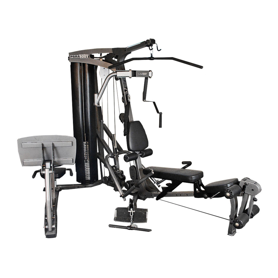
GS6 GYM SYSTEM
WARNING:
Read and follow all directions
for each step to insure proper
Assembly of this product.
CLASS H
PART # 7359601
REV. A
USER'S GUIDE
1
Version: GS6-101
Revision: 11/06/02
Advertisement
Table of Contents

Related Manuals for ParaBody GS6


Summary of Contents for ParaBody GS6
- Page 1 GS6 GYM SYSTEM WARNING: Read and follow all directions for each step to insure proper assembly of this product. USER’S GUIDE CLASS H PART # 7359601 REV. A Version: GS6-101 Revision: 11/06/02...
- Page 2 7. Inspect cables and their connections before using machine. Pay particular attention to the cable ends. DO NOT attempt to fix. Notify your authorized ParaBody dealer before use and have repairs made by an authorized service technician. 8. Make sure all spring loaded pull pins are fully engaged in the adjustment position and fully tighten thumbscrew before use.
-
Page 3: Tools Required For Assembly
Please note: * Thank you for purchasing the ParaBody GS6 Gym System. Please read these instructions thoroughly and keep them for future reference. * This product must be assembled on a flat, level surface to assure its proper function. DO NOT securely tighten any frame connections until the entire frame has been assembled, unless otherwise stated. - Page 4 COMPONENTS PARTS LIST DESCRIPTION PAR T # BASE ACU04-1528 BASE PLATE ACU02-1526 3-1/2” PULLEY GUARD ACU02-1451 REAR FRAME ACU04-1529 FRONT FRAME ACU04-1530 FOOT ASSEMBLY ACU04-1532 PRESS ARM ADJUSTMENT ACU04-1533 LEG EXTENSION HOLDER ACU04-1534 PRESS ARM ACU04-1535 BENCH TUBE ACU04-1536 BENCH BRACE ACU02-1523 FLOATING PULLEY PLATE ACU02-1071...
- Page 5 PART # ACUDA1E012101213NB HEX BOLT 1/2 X 10-1/2 ACUDA1E01271413NB HEX BOLT 1/2 X 7-1/4 ACUDA1E01260013NB HEX BOLT 1/2 X 6 ACUDA1E01241413NB HEX BOLT 1/2 X 4-1/4 ACUDA1C01209213NB HEX BOLT 1/2 X 92mm ACUDA1E01231213NB HEX BOLT 1/2 X 3-1/2 ACUDA1E01230013NB HEX BOLT 1/2 X 3 ACUDA1C01210413NB HEX BOLT 1/2 X 104mm ACUDA1E03853416NB...
-
Page 6: Assembly
3/8 X 3-3/4” 11 FIGURE 1 STEP 1: • SECURELY assemble the REAR FRAME (D) to the BASE (A) using two 3/8 X 3-3/4” BOLTS (11), two 3/8” WASHERS (23) and two 3/8” LOCK NUTS (28) as shown in FIGURE 1. - Page 7 3/8 X 4” 10 FIGURE 2 STEP 2: • LOOSELY assemble two BASE PLATES (B) and the FOOT ASSEMBLY (F) to the BASE (A) using two 3/8 X 4” BOLTS (10) and two 3/8” LOCK NUTS (28). See FIGURE 2.
- Page 8 3/8 X 3-3/4” 11 FIGURE 3 STEP 3: • SECURELY assemble the FRONT FRAME (E) to the BASE PLATES (B) using two 3/8 X 3-3/4” BOLTS (11) and two 3/8” LOCK NUTS (28) as shown in FIGURE 3.
- Page 9 FIGURE 4 • CHECK THAT THE HEADPLATE AND WEIGHT PLATES ARE ASSEMBLED AS SHOWN IN FIGURES 4 & 5 FIGURE 5...
- Page 10 FIGURE 6 OPTIONAL 50 LB. ADD-ON KIT GS-6 SHROUD OPTION ONLY! STEP 6: • Insert two GUIDE RODS (AI) into the REAR FRAME (O) as shown on FIGURE 6. (NOTE: If theGS-6 SHROUD OPTION was purchased, place the GUIDE RODS (AI) through the BOTTOM SHROUD BRACKET (found in SHROUD OPTION box) and into the REAR FRAME (D) as shown in FIGURE 6.
- Page 11 FIGURE 7 11 3/8 X 3-3/4” SECURELY TIGHTEN! 3/8 X 3-3/4” 11 STEP 7: • Swing the GUIDE RODS (AI) into the guide rod bushings in the RIGHT TOP ASSEMBLY (Y) as shown in FIGURE 7. • LOOSELY assemble the RIGHT TOP ASSEMBLY (Y) and the LEFT TOP PLATE (Y) to the REAR FRAME (D) and the FRONT FRAME (E) using three 3/8 X 3-3/4”...
- Page 12 FIGURE 8 7 1/2 X 3” STEP 8: • SECURELY assemble the PEC FLY MOUNT (U) and BACKING PLATE (V) to the FRONT FRAME (E) using two 1/2 X 3” BOLTS (7) and two 1/2” LOCK NUTS (26) as shown in FIGURE 8.
- Page 13 5 1/2 X 92mm 27 1/2” LOW HEIGHT FIGURE 9 STEP 9: • Assemble the RIGHT PEC FLY ARM (T) and LEFT PEC FLY ARM (S) to the PEC FLY MOUNT (U) using two 1/2 X 92mm BOLTS (5), two 3” LONG SPACERS (35), four SHIM WASHERS (25), two 1/2” LOW HEIGHT LOCK NUTS (27) and four RH CAPS (45) as shown in FIGURE 9.
- Page 14 FIGURE 10 STEP 10: • Assemble the PEC HANDLE (P) to the LEFT PEC FLY ARM (S) using one 1/2 X 3/4” BUTTON HEAD BOLT (20) and on 1/2” WASHER (21) as shown in FIGURE 10. • Assemble the PEC HANDLE (P) to the RIGHT PEC FLY ARM (T) using one 1/2 X 3/4” BUTTON HEAD BOLT (20) and on 1/2” WASHER (21) as shown in FIGURE 10.
- Page 15 PLUNGER FIGURE 11 STEP 11: • CAREFULLY slide the SEAT ADJUST (M) onto the SEAT FRAME (AF) as shown. The SEAT can be adjusted and tightened using the PLUNGER PIN. 3/8 X 3-3/4” 11 FIGURE 12 STEP 12: • SECURELY assemble the SEAT FRAME (AF) to the BASE PLATES (B) using two 3/8 X 3-3/4” BOLTS (11) and two 3/8” LOCK NUTS (28) as shown in FIGURE 12.
- Page 16 FIGURE 13 STEP 13: • SECURELY assemble the PIVOT ASSEMBLY (AG) to the SEAT FRAME (AF) using two 3/8 X 2-3/4” BOLTS (15), two 3/8” WASHERS (23) and two 3/8” LOCK NUTS (28) as shown in FIGURE 13. STEP 14: •...
- Page 17 1/2 X 6” 3 STEP 15: • Assemble the SEAT SUPPORT BRACKET (O) to the PIVOT ASSEMBLY (AG) and the BENCH TUBE (J) using two 1/2 X 6” BOLTS (3) and two 1/2” LOW HEIGHT LOCK NUTS (27). (Note: Tighten this connection enough to remove excess play yet allow the BENCH TUBE to rotate freely.) •...
- Page 18 FIGURE 17 STEP 17: • Assemble the LEG PEDESTAL (AD) to the SEAT FRAME (AF) using one 1/2 X 104mm BOLT (8), two SHIM WASHERS (25), one 1/2” LOCK NUT (27) and two RH CAPS (45). (Note: Tighten this connection enough to remove excess play yet allow the LEG PEDESTAL to rotate freely.) 14 3/8 X 3”...
- Page 19 FIGURE 19 STEP 19: • Assemble two 4 X 7” ROLLER PADS (AS) to the LEG PEDESTAL (AD) using two PLASTIC WASHERS (48) and two STARLOCK COLLARS (44) as shown in FIGURE 19. • Assemble two 4 X 7” ROLLER PADS (AS) to the SEAT FRAME (AF) using one 3/4 X 17-1/2” TUBE (AB), two PLASTIC WASHERS (48) and two STARLOCK COLLARS (44) as shown in FIGURE 19.
- Page 20 1/2 X 7-1/4” 2 FIGURE 20 STEP 20: • Insert one 3/4” X 6” SHAFT (36) into the tube on the REAR FRAME (D) as shown. • SECURELY assemble the PRESS LOAD ARM (AE) to the REAR FRAME (D) using one 1/2 X 7-1/4” BOLT (2), one 1/2” WASHER (22) and one 1/2”...
- Page 21 1/2 X 3-1/2” FIGURE 22 STEP 22: • SECURELY assemble the PRESS ARM ADJUSTMENT (G) to the PRESS LOAD ARM (AE) using one 1/2 X 3-1/2” BOLT (6) and one 1/2” LOCK NUT (26) as shown in FIGURE 22. 19 3/8 X 1/2” 29 3/4”...
- Page 22 STEP 24: • Assemble the RIGHT PRESS ARM HANDLE (R) to the PRESS ARM (I) using one 25/32” BUMPER (AO) and one 1/2” LOW HEIGHT LOCK NUT (27) as shown in FIGURE 24. (NOTE: Tighten 1/2” LOW HEIGHT LOCK NUT (27) to remove excess play yet allow the RIGHT PRESS ARM HANDLE (R) to rotate freely.) •...
- Page 23 FIGURE 25 STEP 25: • SECURELY assemble two 2” PLASTIC SLEEVES (46) to the RIGHT TOP ASSEMBLY (X) using two 3/8 X 2-3/4” BOLTS (15) and two 3/8” LOCK NUTS (28) as shown in FIGURE 25(a) • SECURELY assemble two 2-29/32” PLASTIC SLEEVES (47) to the RIGHT TOP ASSEMBLY (X) and LEFT TOP PLATE (Y) using two 3/8 X 3-3/4”...
- Page 24 3/8 X 2” 16 3/8 X 1-3/4” FIGURE 26 STEP 26: • IMPORTANT! Uncoil and straighten all CABLES in order to remove all twist prior to installation • Screw the long threaded end of the LAT CABLE (AV) into the end of the HEAD PLATE (AK) .See FIGURE 26(a) •...
- Page 25 FIGURE 27 STEP 27: • Route the threaded end of the LOW CABLE (AW) thru theSEAT FRAME (AF) and assemble the swivel end of LOW CABLE (AW) to the LEG PEDESTAL (AD) using one 3/8 X 3-1/4” BOLT (13), two 15/16” FLANGE SPACERS (41) and one 3/8” LOCK NUT (28). See FIGURE 27(a) •...
- Page 26 17 3/8 X 1-3/4” 10 3/8 X 4” 11 3/8 X 3-3/4” FIGURE 28 STEP 28: • Assemble one 3-1/2” PULLEY (49) to the BASE PLATES (B) using one 3/8 X 4” BOLT (10), one 3/8 X 15/16” SPACER (30) and one 3/8” LOCK NUT (28).
- Page 27 52 3/8 X 2-1/4” 3/8 X 3-1/2” 12 3/8 X 3” 14 FIGURE 29 STEP 29: • Assemble one 3-1/2” PULLEY (49) to the bracket on the BASE (A) using one 3/8 X 2-1/4” BOLT (52),one 3-1/2” PULLEY GUARD (C), one 3/8” SPACER (31) and one 3/8” LOCK NUT (28). See FIGURE 29(a) (Note: Loop the LOW CABLE (45) around the PULLEY prior to assembling the PULLEY to the BASE .) •...
- Page 28 3/8 X 5-3/4” 9 STEP 30: • Securely assemble the PEC FLY CABLE (AX) to the RIGHT PEC FLY ARM (T) as shown in FIGURE 30(a) • Assemble one 3-1/2” PULLEY (49) to the PEC FLY MOUNT (13) using one 3/8 X 2-3/4” BOLT (15), one 3-1/2” PULLEY GUARD (C) and one 3/8”...
- Page 29 STEP 31: • Securely assemble the ball end of the AB CRUNCH CABLE (AY) and one 4-1/2” V-PULLEY (51) to the FRONT FRAME (E) using two 3/8 X 3-3/4” BOLTS (11), two 3/8 X 19/32” FLANGE SPACERS (42), two 3/8” WASHERS (23) and two 3/8” LOCKNUTS (28). See FIGURE 31(a) (NOTE: The AB CRUNCH CABLE (44) should be routed underneath the retaing bolt as shown in FIGURE 31.) •...
- Page 30 • Attach the AB STRAP (AT) to the ball end of LOW CABLE (AW) using one SNAP LINK (39) as shown in FIGURE 32. Thank you for purchasing the ParaBody GS6 Gym System. If unsure of proper use of equipment, call...
- Page 31 Please note: * We recommend cleaning your product (pads and frame) on a regular basis, using warm soapy water. Touch-up paint can be purchased from your ParaBody customer service representative at (800) 328-9714. * Inspect equipment daily. Tighten all loose connections are replace worn parts immediately.
-
Page 32: Limited Warranty
ParaBody extends the following LIMITED WARRANTY to the original owner of the ParaBody products. The Warranty terms apply to IN HOME USE ONLY. 1. LIMITED WARRANTY ON FRAME AND WELDS. If the frame of the ParaBody product or a weld should crack or break, it will be repaired or replaced by ParaBody. - Page 33 Life Fitness Asia Pacific Limited Room 2610, Miramar Tower 132 Nathan Road, Tsimshatsui Kowloon, Hong Kong Phone: (852) 2891-6677 Fax: (852) 2575-6001 www.parabody.com Life Fitness (UK) Ltd. Queen Adelaide Ely, Cambs CB7 4UB United Kingdom Phone CSS: (01353) 665507 Fax CSS: (01353) 666719 Life Fitness Benelux N.V.