Advertisement
Quick Links
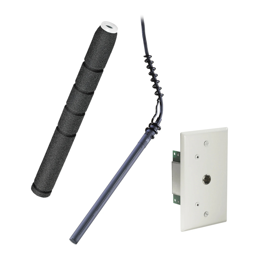
ES933PMML
The microphone's MicroLine
acceptance. Additional interchangeable elements with omnidirec-
tional (360°), cardioid (120°) and hypercardioid (100°) pickup pat-
terns are available.
The microphone features a 50' (15.2 m) permanently attached
miniature cable. Its free end connects to the provided AT8534
wall/ceiling plate power module via TA3F-type connector. The
power module features a white-finished standard electrical cover
plate for easy, secure installation. The microphone can be powered
from any external 11V to 52V DC phantom power supply. Switches
in the power module permit a +10 dB gain setting for extra sensitive
pickup as well as a choice of flat response or low-frequency roll-off
(via integral 80 Hz high-pass UniSteep
undesired ambient noise.
The microphone is enclosed in a rugged housing with a low-
reflectance black finish. It is also available with white housing,
cable and hanger as the ES933PMWML.
INSTALLATION AND OPERATION
The combination of small size and excellent response makes the
ES933PMML ideal for suspension over choirs, instrumental groups
or theater stages. A uniform 90° angle of acceptance provides
well-balanced audio pickup. The microphone should be located
forward of the front-most source, above the rear-most source, and
"aimed" between them (Fig. 1). Increasing the height of the mic
above the sources will tend to equalize sound levels between
them, but may also increase pickup of background or reverberant
sound. Whenever possible, the distance from the mic to the rear-
most source should be no more than twice the distance to the front
source, to maintain front-to-rear balance (Fig. 1).
Width of pickup is approximately 1.5 times the distance to the
closest performer. If additional mics are needed for wide sources,
they should be positioned apart laterally at least 1.5 times the
distance to the front source, to avoid phase cancellation (Fig. 2).
To orient the microphone in the proper direction, twist the housing
slightly in its wire holder (clockwise rotation moves the microphone
to the right; counterclockwise rotation moves it to the left).
The provided foam windscreen simply slips over the head of the
microphone, effectively reducing noise from wind or ventilation air
currents.
An integral 80 Hz high-pass UniSteep
from a flat frequency response to a low-end roll-off. The roll-off
position reduces the pickup of low-frequency ambient noise (such
as traffic, air-handling systems, etc.), room reverberation and
mechanically coupled vibrations. To engage the UniSteep
slide the switch toward the "bent" line.
A 10 dB gain switch is provided for situations that demand extra
sensitive pickup. The +10 position increases the microphone's
MICROLINE
®
CONDENSER
HANGING MICROPHONE
DESCRIPTION
The ES933PMML is a wide-
range miniature condenser
microphone with a MicroLine
polar pattern. It is designed for
quality sound reinforcement,
professional recording, televi-
sion and other demanding
sound pickup applications. The
ES933PMML is furnished with a
vinyl-coated steel hanger that
allows it to be adjusted for
correct positioning. An included
foam windscreen effectively
reduces noise from wind or
ventilation air currents.
The ES933PMML is equipped
with UniGuard
®
RFI-shielding
technology,
which
outstanding rejection of radio
frequency interference (RFI).
The microphone is RoHS com-
pliant – free from all substances
specified in the EU directive on
hazardous substances.
polar pattern provides a 90° angle of
®
®
filter) to help control
®
filter provides easy switching
overall output by 10 dB. To engage the 10 dB gain, slide the switch
toward the +10 position.
®
The AT8534 wall/ceiling plate power module is designed to be
mounted in a standard metal U.S. single-gang electrical box. For
safety and best performance, use the electrical box only for the
AT8534; do not include any AC power conductors. (Also route the
mic cable as far away from AC power cables as possible.)
Screw-terminal output connections of the AT8534 are the same as
those of an XLR-type plug: shield to Terminal 1, balanced signal
and phantom power to Terminals 2 and 3. Output is phased so that
positive acoustic pressure produces positive voltage at Terminal 2,
in accordance with industry convention. Do not connect the output
cable shield to the box. Double-check to make certain that all
input and output leads have no bare wires or loose strands that
could touch each other, the circuit board or the electrical box.
Then attach the power module plate to the electrical box.
offers
Connect the TA3F-type connector from the microphone's cable to
the TA3M-type connector in the power module plate.
NOTE: Audio-Technica has developed a special RFI-shielding
mechanism that is an integral part of the connectors in the
Engineered Sound line. If you remove or incorrectly replace the
connector, you may adversely affect the unit's RFI immunity.
Audio-Technica offers a crimp tool (ATCT) and RFI shields for
TA3F-type, TA5F-type and XLRM-type connectors that enable you
to shorten the cable and correctly reinstall the connector while
maintaining the highest level of RFI immunity.
If you need to shorten the cable between the microphone and
power module, it can be done two ways:
a.If RF integrity must be maintained, the TA3F-type connector can
be removed from the cable end, the cable shortened and the
connector replaced using Audio-Technica's available crimp tool
and RFI shield for TA3F-type connector to maintain original RFI
shielding. (See note above.)
b.If RFI immunity is not required, the TA3M-type connector on the
plate can be removed and discarded (save the back nut and
washer). Assemble the included plastic ferrule into the hole left
from the TA3M-type connector, using the washer and nut from
the connector to secure the ferrule. Cut the cable to the desired
length plus a few inches. Thread the cable through the ferrule
and tie a knot in the cable behind the ferrule to secure it.
Carefully strip the ends of the cable and connect the wires to
the terminals formerly occupied by the TA3M-type connector.
Maintain color coding (Shield - S, Yellow - Y, Red - R) and
connect the microphone wires to the appropriate terminal
screws. (Fig. 3) NOTE: The cable has two red wires and two
yellow wires. Twist the two red wires together and the two yellow
wires together. (Fig. 4)
(Continued on back)
90°
ANGLE OF
ACCEPTANCE
RED/ RED
v+
SIG
YEL / YEL
SHIELD
GND
INPUT
®
filter,
90°
MIC A
1.5 TIMES
DISTANCE "X"
Figure 2
Figure 1
1"
AUDIO -
3
2
AUDIO +
1
SHIELD
1
/
"
2
OUTPUT
Terminal screws
Shield strands,
fully twisted
Figure 4
Figure 3
90°
MIC B
Yellow-Yellow
Red-Red
1
/
" strip reds
8
and yellows
Advertisement

Related Manuals for Audio Technica MICROLINE ES933PMML


Summary of Contents for Audio Technica MICROLINE ES933PMML
- Page 1 Engineered Sound line. If you remove or incorrectly replace the connector, you may adversely affect the unit's RFI immunity. Audio-Technica offers a crimp tool (ATCT) and RFI shields for TA3F-type, TA5F-type and XLRM-type connectors that enable you to shorten the cable and correctly reinstall the connector while maintaining the highest level of RFI immunity.
- Page 2 8 kHz Frequency Response Frequency in Hertz LEGEND 12" or more on axis Roll-off Audio-Technica U.S., Inc., 1221 Commerce Drive, Stow, Ohio 44224 Audio-Technica Limited, Old Lane, Leeds LS11 8AG England www.audio-technica.com P51930 ©2007 Audio-Technica U.S., Inc. † Fixed-charge back plate...