Advertisement
Quick Links
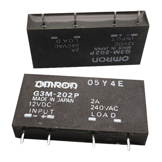
Solid State Relay
G3M
1, 2, 3 and 5 A single in-line package SSR
Thin design for high-density PCB applications.
D
DC input-AC output for up to a 5-A load.
D
Two foot prints offer greater flexibility.
D
Approved by UL and CSA.
D
Ordering Information
To order: Select the part number and add the desired input voltage rating, (e.g., G3M-202P-US DC5)
Isolation
Input terminal
pitch
Phototriac
7.62 mm
Zero cross
Indicator
function
Yes
No
No
(This table continues on the next page.)
Rated output load
Rated input voltage
(Applicable output load)
5 VDC
2 A at 100 to 240 VAC
(2 A at 75 to 264 VAC)
(2 A t 75 t 264 VAC)
12 VDC
24 VDC
5 VDC
3 A at 100 to 240 VAC
(3 A at 75 to 264 VAC)
(3 A t 75 t 264 VAC)
12 VDC
24 VDC
5 VDC
5 A at 100 to 240 VAC
(5 A at 75 to 264 VAC)
(5 A at 75 to 264 VAC)
12 VDC
24VDC
2 A at 100 to 120 VAC
5 VDC
(2 A t 75 t 132 VAC)
(2 A at 75 to 132 VAC)
12 VDC
24 VDC
5 VDC
2 A at 100 to 240 VAC
(2 A t 75 t 264 VAC)
(2 A at 75 to 264 VAC)
12 VDC
24 VDC
3 A at 100 to 240 VAC
5 VDC
(3 A at 75 to 264 VAC)
(3 A t 75 t 264 VAC)
12 VDC
24 VDC
5 VDC
5 A at 100 to 240 VAC
(5 A at 75 to 264 VAC)
(5 A t 75 t 264 VAC)
12 VDC
24 VDC
Solid State Relay
Model
G3M-202P-US
G3M-203P
G3M-205P
G3M-102PL-US
G3M-202PL-US
G3M-203PL
G3M-205PL
G3M
1
Advertisement

Related Manuals for Omron G3M


Summary of Contents for Omron G3M
-
Page 1: Ordering Information
DC input-AC output for up to a 5-A load. Two foot prints offer greater flexibility. Approved by UL and CSA. Ordering Information To order: Select the part number and add the desired input voltage rating, (e.g., G3M-202P-US DC5) Isolation Input terminal Zero cross... -
Page 2: Specifications
Zero cross pitch function Phototriac 5.08 mm Note: 1. TÜV marking is available with “-UTU” in place of “-US” on the part number. 2. VDE versions available. Contact your local OMRON representative. Specifications J RATINGS Input Rated voltage Operating voltage... - Page 3 J CHARACTERISTICS Item G3M-102PL-US (-4) Operate time 1 ms max. (1/2 of load power source cycle + 1 ms max. for G3M-202P, G3M-203P, G3M-205P) Release time 1/2 of load power source cycle + 1 ms max. Output ON voltage drop 1.6 V (RMS) max.
-
Page 4: Engineering Data
Load Current vs. Ambient Temperature (Close Mounting) G3M-205 (5-A Load) Thirty Relays are soldered to the PCB at each given spacing. Continuous power. Solid State Relay Inrush Current Immunity Non-repetitive Reduce the current to 1/2 or less if the G3M is in repetitive operation. - Page 5 Note: All units are in millimeters unless otherwise indicated. G3M-102PL-US(-4), G3M-202P(L)-US(-4) G3M-203P(L)(-4) G3M-205P(L)(-4) Precautions Protective Element No overvoltage absorption element is built in. Therefore, if the G3M is connected to an inductive load, be sure to connect the overvol- tage absorption element. PCB Dimensions (Bottom View) Terminal Arrangement...
- Page 6 III. PRECAUTIONS 1. Suitability: IT IS THE BUYER’S SOLE RESPOINSIBILITY TO ENSURE THAT ANY OMRON PRODUCT IS FIT AND SUFFICIENT FOR USE IN A MOTORIZED VEHICLE APPLICATION. BUYER SHALL BE SOLELY RESPONSIBLE FOR DETERMINING APPROPRIATENESS OF THE PARTICULAR PRODUCT WITH RESPECT TO THE BUYER’S APPLICATION INCLUDING (A) ELECTRICAL OR...
- Page 7 RIOUS RISK TO LIFE OR PROPERTY WITHOUT ENSURING THAT THE SYSTEM AS A WHOLE HAS BEEN DESIGNED TO ADDRESS THE RISKS, AND THAT THE OMRON PRODUCT ISPROPERLY RATED AND INSTALLED FOR THE INTENDED USE WITHIN THE OVERALL EQUIP- MENT OR SYSTEM.
- Page 8 Complete “Terms and Conditions of Sale” for product purchase and use are on Omron’s website at www.omron.com/oei – under the “About Us” tab, in the Legal Matters section. ALL DIMENSIONS SHOWN ARE IN MILLIMETERS. To convert millimeters into inches, multiply by 0.03937. To convert grams into ounces, multiply by 0.03527.