NuTone 8663RP Instruction Manual
Ventilation fan with light
Hide thumbs
Also See for 8663RP:
- Selection manual (36 pages) ,
- Installation instructions manual (13 pages)
Advertisement
Quick Links
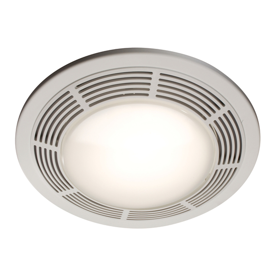
Ventilation Fan
with Light
MODEL: 8663RP, 8664RP
Suitable for use in shower or tub enclosure when used
with GFI protected branch circuit.
Suitable for use in insulated ceilings.
WARNING: To reduce the risk of fire or electrical shock, do not use this
fan with any solid-state speed control device. Do not install in a ceiling
insulated to a value greater than R-40.
IMPORTANT SAFETY INSTRUCTIONS
WARNING – TO REDUCE THE RISK OF FIRE, ELECTRIC SHOCK, OR
INJURY TO PERSONS, OBSERVE THE FOLLOWING:
A. U se this unit only in the manner intended by the manufacturer.
If you have questions, contact the manufacturer.
B. B efore servicing or cleaning unit, switch power off at Service Panel and
lock Service Panel to prevent power from being switched on accidentally.
When the service disconnecting means cannot be locked, securely fas-
ten a prominent warning device, such as a tag, to the service panel.
CAUTION:
For general ventilating use only. Do not use to exhaust hazardous or
explosive materials and vapors.
INSTALLATION INSTRUCTIONS
WARNING – TO REDUCE THE RISK OF FIRE, ELECTRIC SHOCK, OR
INJURY TO PERSONS, OBSERVE THE FOLLOWING:
A. I nstallation work and electrical wiring must be done by qualified person(s)
in accordance with all applicable codes and standards, including fire-rated
construction.
B. S ufficient air is needed for proper combustion and exhausting of gases
through the flue (chimney) of fuel burning equipment to prevent back
drafting. Follow the heating equipment manufacturer's guideline and
safety standards such as those published by the National Fire Protection
Association (NFPA),
and the American Society for Heating, Refrigeration and Air Conditioning
Engineers (ASHRAE), and the local code authorities.
C. W hen cutting or drilling into wall or ceiling, do not damage electrical wiring
and other hidden utilities.
D. D ucted fans must always be vented to the outdoors.
E. I f this unit is to be installed over a tub or shower, it must be marked as
appropriate for the application.
F. N EVER place a switch where it can be reached from a tub or shower.
G. F or installation in sloped ceilings up to 12/12 pitch.
H. D uctwork must point up.
FOR BEST RESULTS
When installing the Exhaust Fan/Light in a new construction site, install
housing during the rough-in construction of the building. The blower unit,
reflector and grille should be installed after the finished ceiling is in place.
Refer to instructions on page 3 to install the Exhaust Fan/Light in an exist-
ing finished building.
PLANNING DUCTWORK AND WIRING
1. U se 4" round duct.
2. P lan duct run from discharge opening of fan to the outside. For best fan
performance, make duct run as short as possible and use minimum num-
ber of elbows.
3. U se optional NuTone ducting accessories as needed.
TO REGISTER THIS PRODUCT, VISIT WWW.NUTONE.COM
READ & SAVE THESE INSTRUCTIONS!
Hanger Bars
Slots
Tabs
Night Light
Socket
(not provided
on 8664RP)
IMPORTANT: Use wire suitable for 90°C.
Plan to run 120vAC house wiring (with ground) from power source, through
wall switches, to junction box in fan. For separate control of fan, light, and
night light three wall switches are required. See NuTone Catalog for accesso-
ry switches. For separate control of fan, light, and night light, five conductors
are needed between the wall switch box and the fan's junction box. (Night
light not provided on 8664RP).
INSTALLATION IN A NEW
CONSTRUCTION SITE
PREPARATION
1. R efer to Figure 1. Remove power unit/blower assembly from housing.
A. U nplug power unit.
B. R emove screw (located next to plug-in receptacle) which holds power/
blower unit mounting plate in place. Save screw.
C. L ift mounting plate at end near the plug-in receptacle until blower
wheel clears the scroll.
D. R emove plate by pulling its tabs out of slots in housing. Set power/
blower unit aside until needed.
2. R emove one of the wiring knockouts from housing.
INSTALLATION INSTRUCTIONS
Wiring
Knockouts
Housing
Scroll
Power/Blower
Unit
Reflector
Assembly
Acorn Nut
Mounting
Springs (2)
Grille/Lens
Assembly
Duct
Collar
FIGURE 1
Advertisement

Related Manuals for NuTone 8663RP


Summary of Contents for NuTone 8663RP
-
Page 1: Important Safety Instructions
Refer to instructions on page 3 to install the Exhaust Fan/Light in an exist- ing finished building. PLANNING DUCTWORK AND WIRING 1. U se 4” round duct. 2. P lan duct run from discharge opening of fan to the outside. For best fan performance, make duct run as short as possible and use minimum num- ber of elbows. 3. U se optional NuTone ducting accessories as needed. TO REGISTER THIS PRODUCT, VISIT WWW.NUTONE.COM READ & SAVE THESE INSTRUCTIONS! INSTALLATION INSTRUCTIONS Hanger Bars Slots Tabs Night Light Socket... -
Page 2: Mounting The Housing
All wiring must comply with local codes and unit must be properly ground- IMPORTANT: Use wire suitable for 90°C. 1. R un 120vAC house wiring from wall switches to fan location, neutral (white), ground (bare copper), and three switched hot leads. See Figure 4. 2. I nsert and secure an approved box connector into wiring entrance hole. 3. P ull wires through box connector and into junction box. Tighten box connector. 4. R efer to Figure 4A. (For 8663RP) C onnect white wires from the fan and light receptacles to white (neutral) wire from the supply. Connect black wire to wire from fan switch. Connect red wire to wire from light switch. Connect yellow wire to wire from night light switch. R efer to Figure 4B. (For 8664RP) C onnect white wires from the fan and light receptacles to white (neutral) wire ... -
Page 3: Completing Installation
POWER/BLOWER UNIT INSTALLATION 1. R efer to Figure 1. Place power/blower unit into housing so that mounting plate’s tabs insert into slots in housing. 2. P ress other end of mounting plate down until it is firmly seated over scroll and plug-in receptacles. 3. S ecure mounting plate to housing with provided screw. 4. I nsert motor plug into junction box receptacle. COMPLETING INSTALLATION 1. I nsert lamp plug into junction box receptacle and secure reflector assembly to motor frame with wing nut provided. 2. I nstall lamps 100 watt (maximum) for light, and 7 watt (maximum) for night light (Night light not provided on 8664RP). 3. S queezing the grille assembly’s mounting springs together, insert springs into slots on both sides of housing. - Page 4 MERCHANTABILITY OR FITNESS FOR A PARTICULAR PURPOSE. During this one year period, Broan-NuTone will, at its option, repair or replace, without charge, any product or part which is found to be defective under normal use and service. THIS WARRANTY DOES NOT EXTEND TO FLUORESCENT LAMP STARTERS OR TUBES, FILTERS, DUCT, ROOF CAPS, WALL CAPS AND OTHER ACCESSORIES FOR DUCTING. This warranty does not cover (a) normal maintenance and service or (b) any products or parts which have been subject to misuse, negligence, accident, improper maintenance or repair (other than by Broan-NuTone), faulty installation or installation contrary to recommended installation instructions.
-
Page 5: Service Parts
ModelS 8663RP & 8664RP KEY NO. 1 1 2 3 4 5 7 7 8 9 10 11 12 13 14 15 ... - Page 6 99044123B...