Table of Contents
Advertisement
Quick Links
Advertisement
Table of Contents

Related Manuals for Nortel Passport 241-5101-200


Summary of Contents for Nortel Passport 241-5101-200
- Page 1 Passport Installation Guide 241-5101-200...
- Page 3 Publication: 241-5101-200 Document status: Standard Document version: R2.2 Document date: October 1999 Copyright © 1999 Nortel Networks. All Rights Reserved. Printed in Canada NORTEL, NORTEL NETWORKS, the globemark design, the NORTEL NETWORKS corporate logo, and PASSPORT are trademarks of Nortel Networks.
- Page 5 Publication history October 1999 R2.2 Standard Commercial availability. Passport 8250 Installation Guide R2.2...
- Page 6 Publication history 241-5101-200 R2.2...
-
Page 7: Table Of Contents
Contents About this document Who should read this guide 11 What you need to know 11 How this guide is organized 11 Conventions 12 Documentation conventions 12 Symbol conventions 13 Related documents 13 Passport documents 13 NMS documents 14 Nortel support services 14 Chapter 1 Passport 8250 Passport 8250 functions 15... - Page 8 Contents Chapter 2 Preparing for the hardware installation Selecting an installation site 21 Unpacking the Passport 8250 shipment 22 Taking inventory of the Passport 8250 shipment 22 Getting the tools to mount the chassis in a rack 24 Chapter 3 Installing the Passport 8250 device Mounting the chassis in a rack 25 Safety precautions 25...
-
Page 9: Contents
Appendix A Replacing hardware Replacing a power supply module 46 Replacing a board module 47 Passport 8250 board guidelines 49 Replacing the fan module 49 Appendix B LEDs Appendix C Standards Product safety standards 55 Electromagnetic compatibility standards 55 Telecom standards 56 Thermal, mechanical, and power standards 56 Regulatory information standards 56 Federal Communications Commission (FCC) 57... - Page 10 Contents 241-5101-200 R2.2...
-
Page 11: About This Document
About this document This document explains how to install the Passport 8250 device. This document uses the terms DS-1/E1 and STM-1/OC-3. The term DS-1/E1 is for information that applies to both DS-1 and E1 interfaces. The term STM-1/OC-3 is for information that applies to both STM-1 and OC-3 ports. When information is for a specific interface or port, the individual designation is given. -
Page 12: Conventions
About this document • “Replacing hardware” (page 45). • “LEDs” (page 51). • “Standards” (page 55). Conventions There are documentation and symbol conventions used in this document. Documentation conventions There are a number of documentation conventions you should know about. •... -
Page 13: Symbol Conventions
• Three dots in a command indicate that the parameter may be repeated more than once in succession. Symbol conventions The following are samples of caution and warning conventions used in this document: Related documents Documents related to the Passport 8250 are available from Passport and NMS documentation suites. -
Page 14: Nms Documents
NTP 241-6001-028, NMS Passport 8250 Tools Guide. • NTP 241-6001-110, NMS Passport 8250 Integration Guide. • NTP 241-6001-807, NMS Backup and Restore User Guide. Nortel support services For information on training, problem reporting, and technical support, contact your Nortel Networks customer representative. 241-5101-200 R2.2... -
Page 15: Passport 8250
Chapter 1 Passport 8250 This section describes the Passport 8250 device. You can view the following topics in this section: • “Passport 8250 functions” (page 15) • “Passport 8250 hardware” (page 16) • “Passport 8250 software” (page 19) • “Related documents” (page 19) Passport 8250 functions The Passport 8250 is an Integrated Access MUX, a rugged, high-density unit that provides a seamless bridge between traditional voice networks and ATM... -
Page 16: Passport 8250 Hardware
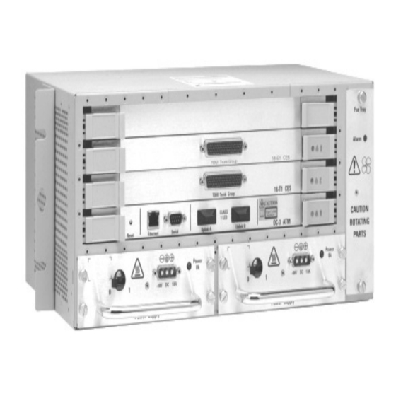
16 Chapter 1 Passport 8250 Figure 1 Passport 8250 device The Passport 8250 can be used for the following applications: • Providing medium to high density DS-1 or E1 ingress to an ATM carrier network. • Providing medium to high density DS-1 or E1 ingress to an ATM wireless network. -
Page 17: Board Modules
See “Passport 8250 front panel” (page 17) for an illustration of the hardware components. Figure 2 Passport 8250 front panel Service board 3 Service board 2 Ethernet Service board 1 port Serial port Board modules The Passport 8250 device has a field-replaceable network board and up to three field-replaceable DS-1/E1 service boards. -
Page 18: Communication Ports
18 Chapter 1 Passport 8250 Communication ports The communication ports, which are located on the network board, include a serial port, ethernet port, and redundant ATM uplink port. Serial port The serial port connects the Passport 8250 device to a local host using a RS-232 cable. -
Page 19: Passport 8250 Software
Passport 8250 software You do not have to order software for the Passport 8250. The Passport 8250 comes preloaded with the operating system and the applications it needs. Base trunking software is included with the integrated trunk/control card (network board), and the CES software with the access modules (service boards), so no service support is required. - Page 20 20 Chapter 1 Passport 8250 241-5101-200 R2.2...
-
Page 21: Preparing For The Hardware Installation
Chapter 2 Preparing for the hardware installation This section provides the following procedures for preparing for installing the Passport 8250 device: “Selecting an installation site” (page 21) “Unpacking the Passport 8250 shipment” (page 22) “Taking inventory of the Passport 8250 shipment” (page 22) “Getting the tools to mount the chassis in a rack”... -
Page 22: Unpacking The Passport 8250 Shipment
After you unpack the Passport 8250 shipment, take inventory of the items using the “Inventory checklist” (page 23) to ensure you received all the items ordered. If you are missing an item, contact your Nortel Networks representative. Note: NMS software and documentation are not included in the inventory checklist. - Page 23 Chapter 2 Preparing for the hardware installation 23 Table 1 Inventory checklist Item Options available Chassis One option available. Fan module One option available. DS-1/E1 DS-1 interface cable assembly, 10m cables DS-1 interface cable assembly, 20m DS-1 interface cable assembly, 30m DS-1 interface cable assembly, 40m DS-1 interface cable assembly, 50m E1 interface cable assembly, 10m...
-
Page 24: Getting The Tools To Mount The Chassis In A Rack
24 Chapter 2 Preparing for the hardware installation Getting the tools to mount the chassis in a rack To mount the chassis in a rack, you will need one or more of the following tools: • 9.5 mm wide flat-bladed screwdriver for 19” or ETSI rack installation. •... -
Page 25: Installing The Passport 8250 Device
Chapter 3 Installing the Passport 8250 device This section provides the following procedures for installing the Passport 8250 device: “Mounting the chassis in a rack” (page 25). “Connecting cables to the ports” (page 29). “Connecting the dual power supply” (page 33). “Securing the cables to the rack”... -
Page 26: Mounting The Passport 8250 Device On A 19" Rack
26 Chapter 3 Installing the Passport 8250 device • Allow at least 2 inches of ventilation space on both sides of the device as illustrated in “Ventilation space” (page 26). • Do not block the air flow around the device with cables. For details, see “Securing the cables to the rack”... - Page 27 Figure 4 Attaching mounting brackets to chassis Figure 5 Installing the chassis on a 19” rack Secure the unit to the rack in four places Chapter 3 Installing the Passport 8250 device 27 Secure mounting brackets to the unit using the fixing holes indicated Allow a minimum of 2SU (88.9 mm) above the unit for...
-
Page 28: Mounting The Passport 8250 Device On A Nebs Or Etsi Rack
28 Chapter 3 Installing the Passport 8250 device Mounting the Passport 8250 device on a NEBS or ETSI rack Locate the bracket mounting holes on each side of the chassis. Attach the mounting brackets to each side of the chassis using a Pozidrive screw driver. -
Page 29: Connecting Cables To The Ports
Connecting cables to the ports You have to connect cables to the following ports: • DS-1/E1 ports. For details on connecting cables, see “Connecting the DS-1/E1 ports” (page 29). • Ethernet port. For details on connecting cables, see “Connecting the ethernet port”... - Page 30 30 Chapter 3 Installing the Passport 8250 device Connect the other end of the DS-1/E1 cable to the far end. Table 2 DS-1/E1 pin assignment Description Signal transmit tip port 0 TXTIPC0 transmit tip port 1 TXTIPC1 transmit tip port 2 TXTIPC2 transmit tip port 3 TXTIPC3...
-
Page 31: Connecting The Ethernet Port
Table 2 (continued) DS-1/E1 pin assignment Description Signal transmit ring port 3 TXRINGC3 transmit ring port 4 TXRINGC4 transmit ring port 5 TXRINGC5 transmit ring port 6 TXRINGC6 transmit ring port 7 TXRINGC7 transmit ring port 8 TXRINGC8 transmit ring port 9 TXRINGC9 transmit ring port 10 TXRINGC10... -
Page 32: Connecting The Serial Port
32 Chapter 3 Installing the Passport 8250 device Connect the other end of the RJ-45 cable to a 10 Base-T ethernet drop or work station. Connecting the serial port Obtain the following equipment: • VT-100 terminal or a PC with terminal-emulation software •... -
Page 33: Connecting The Atm Uplink Port
Connecting the ATM uplink port Obtain the following equipment: • Multi-mode fiber optic cables with SC connectors with a typical range of 0-2 km • Single-mode fiber optic cables with SC connectors with a typical range of 0-15 km Connect the STM-1 or OC-3 single-mode or multi-mode fiber optic cable to port A and port B located on the front panel of the Passport 8250 device. - Page 34 34 Chapter 3 Installing the Passport 8250 device Figure 7 Dual power supply Power supply 1 Obtain the following equipment: • A -48 v DC power supply cable with 3W3-D connector for each power supply module. • Antistatic protection, such as an antistatic glove. If the power supply module is supplied separately, insert the power supply module into an empty power supply slot and tighten the four securing screws with a screw driver.
-
Page 35: Securing The Cables To The Rack
• A double-pole disconnect switch which isolates both the power feed and return conductors. A separate switch shall be provided for each separate power feed to the equipment. • The branch circuit protection shall be located in the ungrounded conductor and be rated at no larger than 30A. - Page 36 36 Chapter 3 Installing the Passport 8250 device Exit and secure all cables to the left as illustrated in “Cables left of chassis” (page 36) or underneath the chassis as illustrated in “Cables underneath chassis” (page 36). Figure 8 Cables left of chassis Figure 9 Cables underneath chassis 241-5101-200 R2.2...
-
Page 37: Configuring The Passport 8250 For Operations
Chapter 4 Configuring the Passport 8250 for operations This section provides the following procedures for configuring the Passport 8250 device for the operations: “Logging into the CLI” (page 37) “Configuring the Passport 8250 device for remote access” (page 38) “Configuring the clocking scheme” (page 40). Logging into the CLI The first time you log into the CLI, you need to do the following: •... -
Page 38: Chapter 4 Configuring The Passport 8250 For Operations
38 Chapter 4 Configuring the Passport 8250 for operations For each power supply module, turn the power supply breaker to ON. Breaker is off. Turn to on. The LEDs on each power supply module is on. Text is displayed on the hyperterminal screen. From the hyperterminal session, stop the Passport 8250 device from starting-up: Press the return key within three seconds of the following text... -
Page 39: Viewing The Boot Parameters
Chapter 4 Configuring the Passport 8250 for operations 39 See “Boot command parameters” (page 39) for the boot parameters you need to configure. Table 3 Boot command parameters boot parameter Description file name The full pathname of the file loaded during a network boot. -
Page 40: Configuring The Clocking Scheme
40 Chapter 4 Configuring the Passport 8250 for operations For host inet, type the IP address of the remote host. If the remote host is on a different network, type the IP address of the gateway node at the gateway inet prompt. For user, type the FTP userid of the remote host. - Page 41 Chapter 4 Configuring the Passport 8250 for operations 41 where configures the clocking scheme for the Passport 8250 device. [set] For details on the clockconfig parameters, see “Clockconfig command parameters” (page 41). Table 4 Clockconfig command parameters Parameter Values External Primary 0 = network board (default) Board Number 1 = service board in slot 1...
-
Page 42: Setting The Clocking Scheme To External Primary
1 = External Primary = clock derived from the primary port. 2 = External Primary Automatic Switching = Clock derived from the primary port. Switch to secondary port if problem with secondary port. 3 = External Secondary = Clock is derived from the secondary port. -
Page 43: Setting The Clocking Scheme To Externalsecondary
Chapter 4 Configuring the Passport 8250 for operations 43 [E1-1]: clockconfig set External Primary Board Number (0 - 3) = 0 2 External Primary Port Number (1 - 16) = 3 10 External Secondary Board Number = 0 External Secondary Port Number = 3 Admin Reference Clock Source: Internal 1 Setting the clocking scheme to ExternalSecondary Display the clockconfig parameters:... -
Page 44: Setting The Reference Clock To Internal
44 Chapter 4 Configuring the Passport 8250 for operations clockconfig [set] For External Primary Board Number, enter a board number. For External Primary Port Number, enter a port number. For External Secondary Board Number, enter a board number. For External Secondary Port Number, enter a port number. For Admin Reference Clock Source, enter 2 for ExternalPrimaryAutomaticSwitchOn: Admin Reference Clock Source: Internal 2... -
Page 45: Appendix A Replacing Hardware
Appendix A Replacing hardware This section provides instructions on how to replace hardware components on the Passport 8250 device. You can view the following procedures in this section: • “Replacing a power supply module” (page 46) • “Replacing a board module” (page 47) •... -
Page 46: Replacing A Power Supply Module
filler pack to ensure proper cooling and air flow. You also need to contact your Nortel Networks representative to order a new power supply module. -
Page 47: Replacing A Board Module
Slide the power supply module or dummy power supply filler pack out of the slot. Insert the new power supply module or dummy power supply filler pack into the empty power supply slot. Using a screw driver, tighten the four securing screws on the sides the power supply module. - Page 48 48 Appendix A Replacing hardware Figure 11 Board slots Service board slot 1 For each power supply module, set the power supply breaker to off. Flip the lock hatch at each end of the circuit board slot open. Slide the network board or service board out of the circuit board slot. Remove the new network board or service board from the package.
-
Page 49: Passport 8250 Board Guidelines
Replacing the fan module If the fan module malfunctions, contact your Nortel Networks representative to order a new fan module. For each power supply module, turn the power supply breaker to off. - Page 50 50 Appendix A Replacing hardware The fans continue to rotate for a few seconds. Remove the new fan module from the package. Insert the new fan module into the empty fan module slot. Tighten the two securing screws on the fan module. For each power supply module, turn the power supply breakers to on.
-
Page 51: Appendix Bleds
Appendix B LEDs The LEDs located on the front panel of the Passport 8250 device. See “Passport 8250 LEDS” (page 52) for an illustration of the LEDs and “LEDs description” (page 53) for a description of the LEDs on the illustration. Passport 8250 Installation Guide R2.2... - Page 52 52 Appendix B LEDs Figure 12 Passport 8250 LEDS Service boards Network board Power supply 1 241-5101-200 R2.2 1 2 3 8 7 6 Power supply 2 Fan module...
- Page 53 Table 5 LEDs description Item color Description green on = system initialized and software loaded on = All provisioned CES connections not working on the service board amber on = at least one, but not all, provisioned CES connection does not work on the service board on = fan failure green on = power available for power supply module...
- Page 54 54 Appendix B LEDs 241-5101-200 R2.2...
-
Page 55: Appendix C Standards
Appendix C Standards This section describes the standards the Passport 8250 device meets. You can view the following topics in this section: • “Product safety standards” (page 55) • “Electromagnetic compatibility standards” (page 55) • “Telecom standards” (page 56) • “Thermal, mechanical, and power standards”... -
Page 56: Telecom Standards
56 Appendix C Standards — FCC Part 15, Class A (USA) — ICES-003, Class A (Canada) — EN 55022, Class A (Europe) • Immunity, ESD, EFT (EU) — EN50082-1 — EN300 386-2 — Bellcore GR-1089-CORE Telecom standards The Passport 8250 device meets the following telecom standards: •... -
Page 57: Federal Communications Commission (Fcc)
Federal Communications Commission (FCC) The Passport 8250 device complies with Part 68 of the FCC rules. On the top of this equipment is a label that contains, among other information, the FCC registration. If requested, this information must be provided to the telephone company. - Page 58 58 Appendix C Standards Before installing this equipment, users should ensure that it is permissible to be connected to the facilities of the local telecommunications company. The equipment must also be installed using an acceptable method of connection. The customer should be aware that compliance with the above conditions may not prevent degradation in service in some situations.
-
Page 59: Index
Index Cable connections ATM uplink port 33 Ethernet port 31 Serial port 32 T1/E1 ports 29 Chassis assembly Installing on 19" rack 26 Installing on NEB or ETSI rack 28 Tools required 24 clockconfig command 40 Hardware replacement Board 47 Fan tray 49 Power supply module 46 Installation site requirements 21... - Page 60 Index 241-5101-200 R2.2...
- Page 62 Passport 8250 Installation Guide R2.2 Copyright © 1999 Nortel Networks. All Rights Reserved. NORTEL, NORTEL NETWORKS, the globemark design, the NORTEL NETWORKS corporate logo, and PASSPORT are trademarks of Nortel Networks. Publication: 241-5101-200 Document status: Standard Document version: R2.2 Document date: October 1999...