Table of Contents
Advertisement
Quick Links
Download this manual
See also:
Reference Manual
Advertisement
Chapters
Table of Contents

Related Manuals for Nortel BayStack 450


Summary of Contents for Nortel BayStack 450
- Page 1 Using the BayStack 450 10/100/1000 Series Switch Software Release V1.3.0 Part No. 302401-D Rev 00 July 1999 4401 Great America Parkway Santa Clara, CA 95054...
-
Page 2: Statement Of Conditions
Nortel Networks NA Inc. does not assume any liability that may occur due to the use or application of the product(s) or circuit layout(s) described herein. - Page 3 Canadian Department of Communications Radio Interference Regulations This digital apparatus (BayStack 450 switch) does not exceed the Class A limits for radio-noise emissions from digital apparatus as set out in the Radio Interference Regulations of the Canadian Department of Communications.
- Page 4 Software is provided will be free from defects in materials and workmanship under normal use for a period of 90 days from the date Software is first shipped to Licensee. Nortel Networks will replace defective media at no charge if it is returned to Nortel Networks during the warranty period along with proof of the date of shipment.
- Page 5 Licensee will immediately destroy or return to Nortel Networks the Software, user manuals, and all copies. Nortel Networks is not liable to Licensee for damages in any form solely by reason of the termination of this license. 8. Export and Re-export. Licensee agrees not to export, directly or indirectly, the Software or related technical data or information without first obtaining any required export licenses or other governmental approvals.
-
Page 7: Table Of Contents
Organization ...xxii Text Conventions ... xxiii Acronyms ... xxiii Related Publications ...xxiv How to Get Help ...xxv Chapter 1 BayStack 450 10/100/1000 Series Switches Physical Description ...1-1 Front Panel ...1-2 Comm Port ...1-3 Uplink/Expansion Slot ...1-3 Port Connectors ...1-3 LED Display Panel ...1-5 Back Panel ...1-8... - Page 8 Port Mirroring ...1-16 Autosensing and Autonegotiation ...1-16 BootP Automatic IP Configuration/MAC Address ...1-17 SNMP MIB Support ...1-18 Configuration and Switch Management ...1-18 Network Configuration ...1-18 Desktop Switch Application ...1-19 Segment Switch Application ...1-20 High-Density Switched Workgroup Application ...1-21 Fail-Safe Stack Application ...1-22 Stack Operation ...1-23...
- Page 9 Installing the BayStack 450 Switch Installation Requirements ...2-1 Installation Procedure ...2-3 Installing the BayStack 450 Switch on a Flat Surface ...2-3 Installing the BayStack 450 Switch in a Rack ...2-4 Attaching Devices to the BayStack 450 Switch ...2-7 Connecting the 10BASE-T/100BASE-TX Ports ...2-8 Connecting Fiber Optic Ports ...2-9...
- Page 10 BootP Always ...3-11 BootP Disabled ...3-11 BootP or Last Address ...3-12 SNMP Configuration ...3-13 System Characteristics ...3-15 Switch Configuration ...3-18 MAC Address Table ...3-20 VLAN Configuration Menu ...3-22 VLAN Configuration ...3-24 VLAN Port Configuration ...3-26 VLAN Display by Port ...3-29 Traffic Class Configuration ...3-30...
- Page 11 Renumber Stack Units ...3-65 Hardware Unit Information ...3-67 Spanning Tree Configuration ...3-67 Spanning Tree Port Configuration ...3-69 Display Spanning Tree Switch Settings ...3-72 TELNET Configuration ...3-75 Software Download ...3-78 Configuration File ...3-82 Display Event Log ...3-85 Excessive Bad Entries ...3-86 Write Threshold ...3-86...
- Page 12 Electromagnetic Immunity ... A-3 Declaration of Conformity ... A-4 Appendix B Gigabit Fiber Optical Characteristics 1000BASE-SX Models ... B-1 Operating Range ... B-1 Transmit Characteristics ... B-2 Receive Characteristics ... B-3 Worst-Case Power Budget and Penalties ... B-3 1000BASE-LX Models ... B-4 Operating Range ...
- Page 13 MDI-X to MDI-X Cable Connections ... E-4 DB-9 (RS-232-D) Console/Comm Port Connector ... E-5 Appendix F Default Settings Appendix G Sample BootP Configuration File Index xiii 302401-D Rev 00...
- Page 15 BayStack 450-12F LED Display Panel ...1-6 Figure 1-5. BayStack 450 Switch Back Panel ...1-9 Figure 1-6. BayStack 450 Switch Used as a Desktop Switch ...1-19 Figure 1-7. BayStack 450 Switch Used as a Segment Switch ...1-20 Figure 1-8. Configuring Power Workgroups and a Shared Media Hub ...1-21 Figure 1-9.
- Page 16 Figure 1-30. VLAN Configuration Spanning Multiple Switches ...1-46 Figure 1-31. IP Multicast Propagation With IGMP Routing ...1-49 Figure 1-32. BayStack 450 Switch Filtering IP Multicast Streams (1 of 2) ...1-50 Figure 1-33. BayStack 450 Switch Filtering IP Multicast Streams (2 of 2) ...1-51 Figure 1-34.
- Page 17 Figure 2-12. Nortel Networks Logo Screen ...2-16 Figure 2-13. Main Menu ...2-18 Figure 2-14. IP Configuration/Setup Screen (Standalone Switch) ...2-19 Figure 2-15. Main Menu (Standalone Switch Example) ...2-21 Figure 2-16. Main Menu (Stack Configuration Example) ...2-21 Figure 2-17. IP Configuration/Setup Screen (Stack Configuration) ...2-22 Figure 3-1.
- Page 18 Figure 3-39. Self-Test Screen After Resetting the Switch ...3-88 Figure 3-40. Nortel Networks Logo Screen ...3-89 Figure 3-41. Self-Test Screen After Resetting to Default Settings ...3-91 Figure 3-42. Nortel Networks Logo Screen After Resetting to Default Settings ...3-92 Figure 3-43. Password Prompt Screen ...3-93 Figure 4-1.
- Page 19 Table 1-1. BayStack 450 Switch LED Descriptions ...1-6 Table 1-2. International Power Cord Specifications ...1-9 Table 2-1. Power-Up Sequence ...2-14 Table 3-1. Console Interface Main Menu options ...3-5 Table 3-2. IP Configuration/Setup Screen Fields ...3-9 Table 3-3. SNMP Configuration Screen Fields ...3-13 Table 3-4.
- Page 20 Table C-4. 1000BASE-LX MDA Components ... C-11 Table E-1. RJ-45 Port Connector Pin Assignments ... E-2 Table E-2. DB-9 Console/Comm Port Connector Pin Assignments ... E-5 Table F-1. Factory Default Settings for the BayStack 450 Switch ...F-1 302401-D Rev 00...
-
Page 21: Preface
Congratulations on your purchase of the BayStack 450 switch, part of the Nortel Networks products. There are three versions of the BayStack 450 switch: the Model 450-24T, the Model 450-12T, and the Model 450-12F. This guide describes the features, uses, and installation procedures for the three versions. (Unless otherwise specified, the terms “BayStack 450 switch”... -
Page 22: Organization
If you want to: Learn about the BayStack 450 switch and its key features Install the BayStack 450 switch on a flat surface or in a 19-inch equipment rack, and verify its operation Connect to the BayStack 450 switch Console/Comm Port and... -
Page 23: Text Conventions
Text Conventions This guide uses the following text conventions: bold text italic text screen text [Enter] [Ctrl]-C Acronyms This guide uses the following acronyms: BootP CSMA/CD 302401-D Rev 00 Indicates command names and options and text that you need to enter. Example: Enter show ip {alerts Example: Use the... -
Page 24: Related Publications
BayStack 400-ST1 Cascade Modules. • Wall Mounting Instructions (Bay Networks part number 304602-A) Describes how to mount up to two BayStack 350 or BayStack 450 switches on any wall that can safely support the weight of the switches, including any attached cables. -
Page 25: How To Get Help
The “Technical Manuals” section lists available printed documentation sets. How to Get Help If you purchased a service contract for your Nortel Networks product from a distributor or authorized reseller, contact the technical support staff for that distributor or reseller for assistance. -
Page 27: Baystack 450 10/100/1000 Series Switches
BayStack 450 10/100/1000 Series Switches This chapter introduces the BayStack 450 switch and covers the following topics: • Physical description • Summary of features • Network configuration examples • Overview of main features Physical Description There are three versions of the BayStack 450 switch: the BayStack 450-24T... -
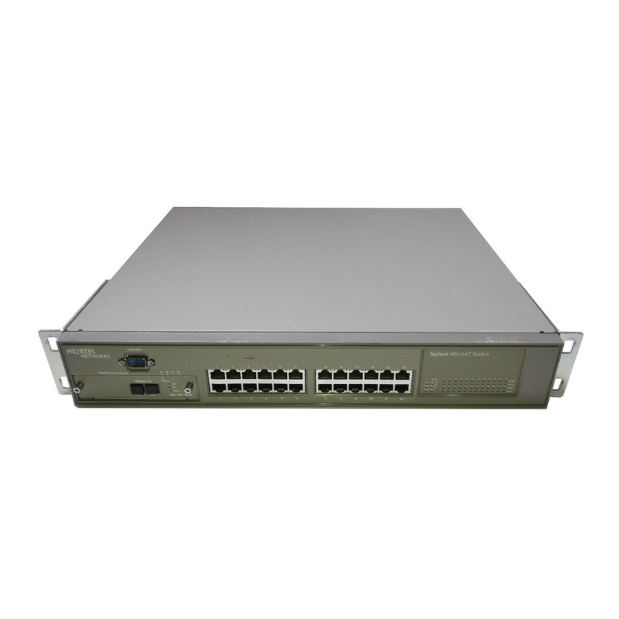
Page 28: Front Panel
Front Panel Figure 1-2 shows the front-panel configurations for the three BayStack 450 switch models. Descriptions of the front-panel components follow the figures. For a description of the components located on the back panel of the BayStack 450 switch, see... -
Page 29: Comm Port
Nortel Networks). Port Connectors 10BASE-T/100BASE-TX Ports The BayStack 450-24T switch and the BayStack 450-12T switch use 10BASE-T/100BASE-TX RJ-45 (8-pin modular) port connectors. Note: The RJ-45 port connectors on BayStack 450 switches manufactured prior to December 1998 are numbered 1 to 12 and 13 to 24, in succession from left to right. - Page 30 (see “MDI and MDI-X Devices” on page E-2). The BayStack 450-24T switch and the BayStack 450-12T switch use autosensing ports that are designed to operate at 10 Mb/s or at 100 Mb/s, depending on the connecting device.
-
Page 31: Led Display Panel
LED Display Panel Figure 1-3 shows the BayStack 450-24T and BayStack 450-12T LED display panels. Figure 1-4 for a description of the LEDs. BayStack Status Dwn RPSU Base BayStack Status RPSU Base = Dual color LED Figure 1-3. 302401-D Rev 00 shows the BayStack 450-12F LED display panel. - Page 32 BayStack Status Dwn RPSU Base = Dual color LED Figure 1-4. Table 1-1. BayStack 450 Switch LED Descriptions Label Type Color Power status Green Status System status Green RPSU RPSU status Green CAS Up Stack mode Green Amber 450-12F Switch...
-
Page 33: Table 1-1. Baystack 450 Switch Led Descriptions
ID (Renumber Stack Unit table full). The unit is on the ring but cannot participate in the stack configuration. The switch is configured as the stack base unit. The switch is not configured as the stack base unit (or is in standalone mode). Blinking Stack configuration error: indicates that multiple base units or no base units are configured in the stack. -
Page 34: Back Panel
The communications link connection is bad or there is no connection to this port. Blinking The corresponding port is management disabled. BayStack 450-12F model only: the corresponding port is in full-duplex mode. The corresponding port is in half-duplex mode Blinking Indicates network activity for the corresponding port. A high level of network activity can cause the LEDs to appear to be on continuously. -
Page 35: Ac Power Receptacle
= RPSU connector = Cascade Module Slot Figure 1-5. BayStack 450 Switch Back Panel AC Power Receptacle The AC power receptacle accepts the AC power cord (supplied). For installation outside of North America, make sure that you have the proper power cord for your region. -
Page 36: Rpsu Connector
Nortel Networks provides an (optional) high-power redundant power supply unit (HRPSU) for this purpose. The HRPSU is a hot-swappable power supply unit that provides uninterrupted operation to up to four BayStack 450 switches in the event that any of the switch power supplies fail. -
Page 37: Cascade Module Slot
The Cascade Module slot allows you to attach an optional BayStack 400-ST1 Cascade Module to the switch (see You can connect up to eight BayStack 450 switches into a redundant stack configuration. BayStack 450 switches use a fail-safe cascade stacking architecture which, in the unlikely event of a switch failure, maintains the integrity of the remaining stack: all signals are looped back at the point of failure. - Page 38 Nortel Networks sales representative for ordering information). • Spanning Tree Protocol (STP): complies with IEEE 802.1D standard. STP can be disabled on the entire switch or stack, or on a per-port basis. • SNMP agent support for the following management information bases...
- Page 39 • TELNET: -- Support for up to four simultaneous TELNET sessions -- Optional password protection -- Login time-out -- Failed-login guard -- Inactivity time-out -- Allowed source addresses -- Event logging • IEEE 802.3u-compliant autonegotiation ports, with four modes: -- 10BASE-T half-duplex -- 10BASE-T full-duplex -- 100BASE-TX half-duplex -- 100BASE-TX full-duplex...
-
Page 40: Ieee 802.1P Prioritizing
-- History -- Alarms -- Events IEEE 802.1p Prioritizing The BayStack 450 switch can prioritize the order in which packets are forwarded, on a per-port basis. For more information about the 802.1p prioritizing feature, see Prioritizing” on IEEE 802.1Q VLANs BayStack 450 switches support up to 64 port-based VLANs with IEEE 802.1Q... -
Page 41: Igmp Snooping Feature
An in-band connection between the switch and the TFTP load host is required to download the software image. If a BootP server is set up properly on the network and the BayStack 450 switch detects a corrupted software image during the self-test, the switch automatically uses TFTP to download a new software image. -
Page 42: Multilink Trunking
800 Mb/s in full-duplex mode. BayStack 450 switches can be configured with up to six MultiLink Trunks. The trunk members can be configured within a single unit in the stack or distributed between any of the units within the stack configuration (distributed trunking). -
Page 43: Bootp Automatic Ip Configuration/Mac Address
“Autonegotiation Modes” on page 4-8. BootP Automatic IP Configuration/MAC Address The BayStack 450 switch has a unique 48-bit hardware address, or MAC address, that is printed on a label on the back panel. You use this MAC address when you configure the network BootP server to recognize the BayStack 450 switch BootP requests. -
Page 44: Snmp Mib Support
For a complete listing of supported MIBs, see “Features” on Configuration and Switch Management The BayStack 450 switch is shipped directly from the factory ready to operate in any 10BASE-T or 100BASE-TX standard network. You can manage the switch using the Nortel Networks Optivity generic SNMP-based network management software;... -
Page 45: Desktop Switch Application
Note: All models of the BayStack 450 switch can be used interchangeably in the following network configuration examples. Desktop Switch Application Figure 1-6 shows a BayStack 450-24T switch used as a desktop switch, where desktop workstations are connected directly to switch ports. -
Page 46: Segment Switch Application
Segment Switch Application Figure 1-7 shows a BayStack 450-24T switch used as a segment switch to alleviate user contention for bandwidth and eliminate server and network bottlenecks. Before segmentation, 88 users had a total bandwidth of only 10 Mb/s available. After segmentation, 92 users have 40 Mb/s, four times the previous bandwidth, while adding 22 dedicated 100 Mb/s connections. -
Page 47: High-Density Switched Workgroup Application
BayStack 450 switch with an optional gigabit (1000BASE-SX) MDA for maximum bandwidth. The BayStack 303 and 304 switches have 100 Mb/s connections to the BayStack 450 switch, a 100BASE-TX hub, and a 100 Mb/s server and 10 Mb/s connections to DTE (data terminal equipment). -
Page 48: Fail-Safe Stack Application
Fail-Safe Stack Application Figure 1-9 shows an example of eight BayStack 450 switches that are stacked together as a single managed unit. If any single unit in the stack fails, the remaining stack remains operational, without interruption. As shown in connecting to the BayStack 450 switch with an optional gigabit (1000BASE-SX) MDA for maximum bandwidth. -
Page 49: Stack Operation
BayStack 450 switches that are configured with BayStack 450 software versions earlier than version V1.1.0. If you need to upgrade your BayStack 450 switches, refer to the upgrade instructions provided in the Installing the BayStack 400-ST1 Cascade Module guide. You must upgrade the switch before installing the BayStack 400-ST1 Cascade Module. -
Page 50: Cascade A Out Connector
The Unit Select switch (up = Base) determines the base unit for the stack configuration (see displayed on the BayStack 450 LED display panel. When the Unit Select switch is in the Base (up) position, all other Unit Select switches in the stack configuration must be set to Off (down). -
Page 51: Base Unit
The base unit is the unique stack unit that you configure with the Unit Select switch on the front panel of the 400-ST1 cascade module. One unit in the stack must be configured as the base unit; all other units in the stack must have their Unit Select switch set to Off (see “Unit Select... -
Page 52: Stack Mac Address
For this reason, you should always assign the temporary base unit as the base unit (set the Unit Select switch to Base) until the failed unit is repaired or replaced. -
Page 53: Removing A Unit From The Stack
As shown in panel provide the ability to stack up to eight BayStack switches. With 400-4TX MDAs installed in each switch, the stack can accommodate a maximum of 224 switch ports. Because stack parameters are associated with the base unit (see page 1-25), the physical stack order depends on the base unit’s position and... -
Page 54: Stack Up Configurations
1-12, data flows from the base unit (unit 1) to the next switch, which is assigned as unit 2, and continues until the last switch in the stack is assigned as unit 8. The physical order of the switches is from bottom to top (unit 1 to unit 8). - Page 55 (GUI) that represents the stack (see Figure 1-13). For this reason, Nortel Networks recommends that you always configure the top unit in the stack as the base unit. In any stack configuration, the following applies: •...
-
Page 56: Redundant Cascade Stacking Feature
Redundant Cascade Stacking Feature BayStack 450 switches allow you to connect up to 8 units into a redundant cascade stack. If any single unit fails or if a cable is accidently disconnected, other units in the stack remain operational, without interruption. - Page 57 Unit 1 Unit 2 Unit 3 Unit 4 Unit 5 1 = Base unit 2 = Last unit 3 = Cascade cable (PN 303978-A) 4 = Cascade max-return cable (PN 303979-A) Figure 1-14. 302401-D Rev 00 Cascade A Out Redundant Cascade Stacking Feature Cascade A In BS0035B 1-31...
-
Page 58: Ieee 802.1Q Vlan Workgroups
VLAN, it is added to a group of ports (workgroup) that belong to one broadcast domain. The BayStack 450 switch allows you to assign ports to VLANs using the console or TELNET; VLAN assignment is not currently available through SNMP. You can assign different ports (and therefore the devices attached to these ports) to different broadcast domains. -
Page 59: Ieee 802.1Q Tagging
IEEE 802.1Q Tagging BayStack 450 switches operate in accordance with the IEEE 802.1Q tagging rules. Important terms used with the 802.1Q tagging feature are: • VLAN identifier (VID) -- the 12-bit portion of the VLAN tag in the frame header that identifies an explicit VLAN. - Page 60 • Filtering database identifier (FID) -- the specific filtering/forwarding database within the BayStack 450 switch that is assigned to each VLAN. The current version of software assigns all VLANs to the same FID. This is referred to as Shared VLAN Learning in the IEEE 802.1Q specification.
- Page 61 802.1Q Tagging (1 of 4) As shown in switch through port 5, which is configured as a tagged member of VLAN 2. The untagged packet remains unchanged as it leaves the switch through port 7, which is configured as an untagged member of VLAN 2.
- Page 62 802.1Q Tagging (3 of 4) As shown in switch through port 5, which is configured as a tagged member of VLAN 2. However, the tagged packet is stripped (untagged) as it leaves the switch through port 7, which is configured as an untagged member of VLAN 2.
-
Page 63: Vlans Spanning Multiple Switches
VLAN 1 and VLAN 2. Both ports are tagged members of VLAN 1 and VLAN 2 Figure 1-21. 302401-D Rev 00 shows VLANs spanning two BayStack 450 switches. The 802.1Q VLAN 1 VLANs Spanning Multiple 802.1Q Tagged Switches VLAN 2 BayStack 450-24T BayStack 450-24T... -
Page 64: Vlans Spanning Multiple Untagged Switches
VLANS Spanning Multiple Untagged Switches Figure 1-22 configuration switch S2 does not support 802.1Q tagging and you must use a single switch port on each switch for each VLAN. For this configuration to work properly, you must set spanning tree participation to Disabled (the STP is not supported across multiple LANs). - Page 65 Because the other link connecting VLAN 2 is in Blocking mode, stations on VLAN 2 in switch S1 cannot communicate with stations in VLAN 2 on switch S2. With multiple links only one link will be forwarding.
-
Page 66: Shared Servers
Shared Servers BayStack 450 switches allow ports to exist in multiple VLANs for shared resources, such as servers, printers, and switch-to-switch connections. It is also possible to have resources exist in multiple VLANs on one switch as shown in Figure 1-24. - Page 67 VLAN 3 broadcast domain shown in 302401-D Rev 00 VLAN 3 VLAN 2 Port 4 Port 10 Port 8 PVID = 3 VLAN Broadcast Domains Within the Switch VLAN 1 Port 6 Port 11 PVID = 1 BS45019A Figure Figure 1-25.
- Page 68 To configure the VLAN port membership for VLAN 1: Select Switch Configuration from the BayStack 450-12T Main Menu (or press w). From the Switch Configuration Menu, select VLAN Configuration (or press v). From the VLAN Configuration Menu select VLAN Configuration (or press v).
- Page 69 Ports 2, 4, 6, 8, 10, and 11 are now untagged members of VLAN 3 as shown in Figure 1-25 Port Membership 7-12 ------ ------ Unit #1 -U-U-U -U-UU- KEY: T = Tagged Port Member, U = Untagged Port Member, - = Not a Member of VLAN Use space bar to display choices, press <Return>...
- Page 70 Unit: Port: Filter Tagged Frames: Filter Untagged Frames: Filter Unregistered Frames: Port Name: PVID: Port Priority: Tagging: Use space bar to display choices, press <Return> or <Enter> to select choice. Press Ctrl-R to return to previous menu. Figure 1-28. Default VLAN Port Configuration Screen Example Figure 1-29 support the PVID assignment for port 8, as shown in optional).
-
Page 71: Vlan Workgroup Summary
VLAN Port Configuration [ No [ No [ No [ Student port ] [Untagged Access] Press Ctrl-C to return to Main Menu. Figure 1-30, switch S1 (a BayStack 450 switch) is configured with “VLANS Spanning Multiple Untagged page 1-38). 1-45... - Page 72 The connection to S2 requires only one link between the switches because S1 and S2 are both BayStack 450 switches that support 802.1Q tagging (see Spanning Multiple 802.1Q Tagged Non-802.1Q tagging switch Untagged ports (STP disabled) BayStack 450-24T VLAN 1 (PVID=1)
-
Page 73: Vlan Configuration Rules
VLAN Configuration Rules VLANs operate according to specific configuration rules. When creating VLANs, consider the following rules that determine how the configured VLAN reacts in any network topology: • All ports that are involved in port mirroring must have memberships in the same VLANs. -
Page 74: Igmp Snooping
IP Multicast router. After the pathway is established, the BayStack 450 switch blocks the IP Multicast stream from exiting any other port that does not connect to another host member, thus conserving bandwidth. The... - Page 75 Figure 1-31. IP Multicast Propagation With IGMP Routing The BayStack 450 switch can automatically set up IP Multicast filters so the IP Multicast traffic is only directed to the participating end nodes (see Figure 1-32, switches S1 to S4 represent a LAN connected to an IP Multicast router.
- Page 76 Figure 1-32. BayStack 450 Switch Filtering IP Multicast Streams (1 of 2) Switch S1 treats the consolidated proxy reports from S2 and S4 as if they were reports from any client connected to its ports, and generates a consolidated proxy report to the designated router.
- Page 77 IP Multicast Internet Figure 1-33. BayStack 450 Switch Filtering IP Multicast Streams (2 of 2) The consolidated proxy report generated by the switch remains transparent to layer 3 of the International Organization for Standardization, Open Systems Interconnection (ISO/OSI) model. (The switch IP address and MAC address are not part of proxy report generation.) The last reporting IGMP group member in...
-
Page 78: Igmp Snooping Configuration Rules
IGMP Snooping Configuration Rules The IGMP snooping feature operates according to specific configuration rules. When configuring your switch for IGMP snooping, consider the following rules that determine how the configuration reacts in any network topology: • A port that is configured for port mirroring cannot be configured as a static router port. -
Page 79: Ieee 802.1P Prioritizing
VLAN 2 Outgoing untagged packet (unchanged) Figure 1-34. Prioritizing Packets The newly tagged frame is read within the switch and sent to the port’s high or low transmit queue for disposition (see shown in Figure 1-35 302401-D Rev 00 Tagged member... -
Page 80: 302401-D Rev 00
802.1p capable switch. This allows the packet to carry the assigned traffic class priority through the network until it reaches its destination. -
Page 81: Figure 1-36. Default Traffic Class Configuration Screen Example
To configure the port priority level, follow these steps: Determine the priority level you want to assign to the switch port. User priority levels are assigned default settings in all BayStack 450 switches. The range is from 0 to 7. The traffic class table can be modified; therefore, view the settings shown in the Traffic Class Configuration screen before setting the port priority in the VLAN Port Configuration screen. -
Page 82: Figure 1-37. Setting Port Priority Example
Select a priority level from the range shown in the Traffic Class Configuration screen (or modify the Traffic Class parameters to suit your needs). Assign the priority level to ports using the VLAN Port Configuration screen: Press [Ctrl]-R to return to the VLAN Configuration Menu. From the VLAN Configuration Menu, select VLAN Port Configuration (or press c). -
Page 83: Multilink Trunks
MultiLink Trunks MultiLink Trunks allow you to group up to four switch ports together to form a link to another switch or server, thus increasing aggregate throughput of the interconnection between the devices (up to 800 Mb/s in full-duplex mode). You can configure up to six MultiLink Trunks. -
Page 84: Client/Server Configuration Using Multilink Trunks
Client/Server Configuration Using MultiLink Trunks Figure 1-40 client/server configuration. In this example, both servers connect directly to switch S1. FS2 is connected through a trunk configuration (T1). The switch-to-switch connections are through trunks (T2, T3, T4, and T5). 1-58 shows a typical switch-to-server trunk configuration. In this example,... - Page 85 Clients accessing data from the servers (FS1 and FS2) are provided with maximized bandwidth through trunks T1, T2, T3, T4, and T5. Trunk members (the ports making up each trunk) do not have to be consecutive switch ports; you can select ports randomly, as shown by T5.
-
Page 86: Trunk Configuration Screen Examples
1-72, and “MultiLink Trunk Configuration” on page 3-37 for more information. Trunk Configuration Screen for Switch S1 Switch S1 is set up with five trunk configurations: T1, T2, T3, T4, and T5. Setting up the Trunk Configuration For S1: To set up the trunk configuration, choose MultiLink Trunk Configuration (or press t) from the MultiLink Trunk Configuration Menu screen Use arrow keys to highlight option, press <Return>... - Page 87 MultiLink Trunk Configuration Screen for Switch S1 Switch S1 is configured as follows: • Trunk (read only) indicates the trunks (1 to 6) that correspond to the switch ports specified in the Trunk Members fields. • Trunk Members (Unit/Port) indicates the ports that can be configured, in...
- Page 88 Trunk Name indicates optional fields for assigning names to the corresponding configured trunks. The names chosen for this example provide meaningful information to the user of this switch (for example, S1:T1 to FS2 indicates that Trunk 1, in switch S1, connects to File Server 2). 1-62...
-
Page 89: Trunk Configuration Screen For Switch S2
MultiLink Trunk Configuration Screen for Switch S2 Switch S2 is configured as follows: • Trunk (read only) indicates the trunks (1 to 6) that correspond to the switch ports specified in the Trunk Members fields. • Trunk Members (Unit/Port) indicates the ports that can be configured, in each row, to create the corresponding trunk: Ports 25 and 26 are assigned as trunk members of trunk 1. - Page 90 Trunk Name indicates optional fields for assigning names to the corresponding configured trunks. The names chosen for this example provide meaningful information to the user of this switch (for example, S2:T2 to S1 indicates that Trunk 1, in switch S2, connects to Switch 1). 1-64...
-
Page 91: Trunk Configuration Screen For Switch S3
MultiLink Trunk Configuration Screen for Switch S3 Switch S3 is configured as follows: • Trunk (read only) indicates the trunk (1 to 6) that corresponds to the switch ports specified in the Trunk Members fields. • Trunk Members (Unit/Port) indicates the ports that can be configured, in each row, to create the corresponding trunk: Ports 1 and 3 are assigned as trunk members of trunk 1. - Page 92 Trunk Name indicates optional fields for assigning names to the corresponding configured trunks. The names chosen for this example provide meaningful information to the user of this switch (for example, S3:T4 to S1 indicates that Trunk 1, in switch S3, connects to Switch 1). 1-66...
-
Page 93: Trunk Configuration Screen For Switch S4
Figure 1-45. MultiLink Trunk Configuration Screen for Switch S4 302401-D Rev 00 Figure 1-40, switch S4 is set up with one trunk configuration (T5). shows the MultiLink Trunk Configuration screen for switch S4. MultiLink Trunk Configuration STP Learning ] [ Normal... - Page 94 Switch S4 is configured as follows: • Trunk (read only) indicates the trunk (1 to 6) that corresponds to the switch ports specified in the Trunk Members fields. • Trunk Members (Unit/Port) indicates the ports that can be configured, in each row, to create the corresponding trunk: Ports 5 and 11 are assigned as trunk members of trunk T1.
-
Page 95: Before Configuring Trunks
Before Configuring Trunks When you create and enable a trunk, the trunk members (switch ports) take on certain settings necessary for correct operation of the MultiLink Trunking feature. Before configuring your MultiLink Trunk, you must consider these settings, along with specific configuration rules, as follows:... - Page 96 • All trunk members must have the same VLAN configuration before the Trunk Configuration screen’s Trunk Status field can be set to Enabled (see “VLAN Configuration” on page 3-24). • When an active port is configured in a trunk, the port becomes a trunk member when you set the Trunk Status field to Enabled.
-
Page 97: How The Multilink Trunk Reacts To Losing Distributed Trunk Members
Port Configuration • IGMP Configuration • Rate Limiting Configuration 302401-D Rev 00 (Figure 1-46) spans separate units in a stack BayStack 450-24T Switches 450-1SR MDA 450-1SR MDA 450-1SR MDA 450-1SR MDA CPU PS1 PS2 FAN Unit 1 Unit 2 Unit 3... -
Page 98: Spanning Tree Considerations For Multilink Trunks
Spanning Tree Considerations for MultiLink Trunks The spanning tree Path Cost parameter is recalculated based on the aggregate bandwidth of the trunk. For example, with two port members operating at 100 Mb/s and two at 10 Mb/s. Trunk T1 provides an aggregate bandwidth of 220 Mb/s. The Path Cost for T1 is 4 (Path Cost = 1000/LAN speed, in Mb/s). - Page 99 The switch can also detect trunk member ports that are physically misconfigured. For example, in configured correctly to trunk member ports 7, 9, and 11 of switch S2. The Spanning Tree Port Configuration screen for each switch shows the port state field for each port in the Forwarding state.
-
Page 100: Figure 1-49. Example 2: Detecting A Misconfigured Port
Using the BayStack 450 10/100/1000 Series Switch If switch S2’s trunk member port 11 is physically disconnected and then reconnected to port 13, the Spanning Tree Port Configuration screen for switch S1 changes to show port 6 in the Blocking state (Figure 1-49). -
Page 101: Additional Tips About The Multilink Trunking Feature
BayStack 450 10/100/1000 Series Switches Additional Tips About the MultiLink Trunking Feature When you create a MultiLink Trunk, the individual trunk members (the specific ports that make up the trunk) logically connect and react as a single entity. For example, if you change spanning tree parameters for any trunk member, the spanning tree parameters for all trunk members change. -
Page 102: Port Mirroring (Conversation Steering)
Note: A probe device, such as the Nortel Networks StackProbe equivalent, must be connected to the designated monitor port to use this feature (contact your Nortel Networks sales agent for details about the StackProbe). The following sections provide sample configurations for both monitoring modes available with the Port Mirroring feature: •... -
Page 103: Port-Based Mirroring Configuration
23 is designated as the monitor port for ports 24 and 25 of switch S1. Although this example shows ports 24 and 25 monitored by the monitor port (port 23), any of the trunk members of T1 and T2 can also be monitored. - Page 104 • As shown in the Port Mirroring Configuration screen example port 23 is designated as the Monitor Port for ports 24 and 25 in switch S1. Note: The Unit value (in the Unit/Port field) is not configurable when the switch is operating standalone. For detailed information about the MultiLink Trunk Configuration screen fields, see “MultiLink Trunk Configuration”...
-
Page 105: Address-Based Mirroring Configuration
Figure 1-51. Port Mirroring Port-Based Screen Example Address-Based Mirroring Configuration Figure 1-52 port 23, the designated monitor port for switch S1, is monitoring traffic occurring between address A and address B. 302401-D Rev 00 Port Mirroring Configuration -> Port X... -
Page 106: Figure 1-52. Address-Based Mirroring Configuration Example
Figure 1-52. In this configuration, the designated monitor port (port 23) can be set to monitor traffic in any of the following modes: • Monitor all traffic transmitted from address A to any address. • Monitor all traffic received by address A from any address. •... - Page 107 In this example, port 23 becomes the designated Monitor Port for switch S1 when you press Enter in response to the [Yes] screen prompt. Note: The screen data displayed at the bottom of the screen changes to show the new currently active port mirroring configuration after you press Enter.
-
Page 108: Port Mirroring Configuration Rules
When you configure a port as a monitor port, the port is automatically disabled from participating in the spanning tree. When you reconfigure the port as a standard switch port (no longer a monitor port), the port is enabled for spanning tree participation. -
Page 109: Installing The Baystack 450 Switch
Note: Be sure that the supplied AC power cord matches the requirements for your region; see “AC Power Receptacle” on page 1-9. Install the BayStack 450 switch in a ventilated area that is dust free and away from heat vents, warm air exhaust from other equipment, and direct sunlight. Avoid proximity to large electric motors or other electromagnetic equipment. -
Page 110: Figure 2-1. Package Contents
If any items are missing or damaged, contact the sales agent or the customer service representative from whom you purchased the BayStack 450 switch. BayStack 450 switch... -
Page 111: Installation Procedure
This section provides the requirements and instructions for installing the BayStack 450 switch on a flat surface or in a standard 19-inch utility rack. If you install the switch in a rack, ground the rack to the same grounding electrode used by the power service in the area. -
Page 112: Installing The Baystack 450 Switch In A Rack
The BayStack 450 switch can be mounted onto any appropriate flat, level surface that can safely support the weight of the switch and its attached cables, as long as there is adequate space around the unit for ventilation and access to cable connectors. -
Page 113: Figure 2-2. Positioning The Chassis In The Rack
Tali staffe non possono essere utilizzate per fissare più unità. The BayStack 450 switch occupies a 1.6-unit (1.6u) rack space and can be installed in most standard 19-inch racks. The rack must be grounded to the same grounding electrode used by the power service in the area. - Page 114 Figure 2-3. Position the switch in the rack and align the holes in the mounting bracket with the holes in the rack (see Figure 2-4. Attaching Mounting Brackets Installing the BayStack 450 Switch in an Equipment Rack (Figure 2-3). BS45036A Figure 2-4).
-
Page 115: Attaching Devices To The Baystack 450 Switch
Devices to the BayStack 450 Attaching Devices to the BayStack 450 Switch This section describes how to attach devices to the BayStack 450 switch ports and how to connect a console terminal to the switch Console/Comm port. You can use the console terminal to observe the power on self-test results and set up the switch, if required, as described later in this chapter. -
Page 116: Connecting The 10Base-T/100Base-Tx Ports
See Appendix E, “Connectors and Pin Assignments,” for more information. By default, all BayStack 450 switch 10BASE-T/100BASE-TX switch ports are set with autonegotiation enabled. This feature allows any port to match the best service provided by the connected station, up to 100 Mb/s in full-duplex mode. -
Page 117: Connecting Fiber Optic Ports
Connecting Fiber Optic Ports Connect devices to the fiber optic ports as shown in The BayStack 450-12F switch and the (optional) 400-4FX MDA are 100BASE-FX devices. Both products use MT-RJ port connectors with 62.5/125 micron multimode fiber optic cable. The 400-2FX MDA is also a 100BASE-FX device but uses standard SC port connectors with 62.5/125 micron multimode... -
Page 118: Console/Comm Port
You can also connect this port to an external modem to enable remote dial-in management of the switch. The port is a male DB-9 connector, implemented as a data communication equipment (DCE) connection. -
Page 119: Connecting A Terminal To The Console/Comm Port
Figure 2-7. Connect the other end of the cable to a terminal or the serial connector of a personal computer running communications software. See the next section, and power up the BayStack 450 switch. 302401-D Rev 00 Figure 2-7). Comm Port... -
Page 120: Connecting Power
Connecting Power The BayStack 450 switch does not have a power on/off switch. When you connect the AC power cord to a suitable AC power outlet, the switch powers up immediately. Warning: Removal of the power cord is the only way to turn off power to this device. - Page 121 Plug the other end of the AC power cord into the grounded AC power outlet (Figure Figure 2-9. See the next section, 302401-D Rev 00 (Figure 2-8). Cascade Module BS45039A BayStack 450 Switch AC Power Receptacle 2-9). 612FA Grounded AC Power Outlet “Verifying the Installation.” 2-13...
-
Page 122: Verifying The Installation
When power is applied to the switch, power-on self-tests run. You can verify proper operation of the BayStack 450 switch by observing the front-panel LEDs or by viewing the self-test results as displayed in the BayStack 450 switch Self-Test screen. -
Page 123: Verifying The Installation Using The Self-Test Screen
Verifying the Installation Using the Self-Test Screen If a monitor is connected to the switch (see you can observe the BayStack 450 switch Self-Test screen example of a standalone switch Self-Test screen). The results of the self-test are displayed briefly (5 or 10 seconds) on the Self-Test... -
Page 124: Figure 2-12. Nortel Networks Logo Screen
Enter Ctrl-Y to begin. Figure 2-12. Nortel Networks Logo Screen Note: The Nortel Networks logo screen for your switch will display the BayStack 450 model number and the current hardware, firmware, and software versions. Upon successful completion of the power-up self-tests, the switch is ready for normal operation. -
Page 125: Initial Setup
A minimal configuration is required when you plan on remote management or TFTP operations. If you are configuring your BayStack 450 switches into a stack configuration, you will need to supply additional parameters to properly set up the stack. - Page 126 Select IP Configuration/Setup (or press i) from the Main Menu. This selection displays the IP Configuration/Setup screen Note: The IP interface of the BayStack 450 switch is only on VLAN 1. You can manage the switch only from VLAN 1 (or via routers that connect VLAN 1 to the network management station).
- Page 127 Press Ctrl-R to return to previous menu. Figure 2-14. IP Configuration/Setup Screen (Standalone Switch) Enter the IP address of the switch in the In-Band IP Address field, then press [Return]. Note: When you enter the IP address in the In-Band IP Address field, and...
-
Page 128: Stack Setup
For the initial setup of a stack configuration, you need to enter the stack IP address, the subnet mask, and the gateway address (see Chapter 3, “Using the Console Interface,” for more information about configuring your BayStack 450 switch). To set the stack IP address, subnet mask, and gateway address for the switch, follow these steps: Note: Unless otherwise specified, the terms “switch”... -
Page 129: Figure 2-15. Main Menu (Standalone Switch Example)
Main Menu (Standalone Switch Example) Use arrow keys to highlight option, press <Return> or <Enter> to select option. Figure 2-16. Main Menu (Stack Configuration Example) 302401-D Rev 00 BayStack 450-24T Main Menu IP Configuration/Setup... SNMP Configuration... System Characteristics... Switch Configuration... - Page 130 Select IP Configuration/Setup (or press i) from the Main Menu. This selection displays the IP Configuration/Setup screen Note: The IP interface of the BayStack 450 switch is only on VLAN 1. You can manage the switch only from VLAN 1 (or via routers that connect VLAN 1 to the network management station).
- Page 131 Note: IP addresses are written as four decimal numbers (for example, 123.123.123.123). Each decimal number represents an 8-bit octet. When strung together, the four octets form the 32-bit Internet address. This is called dotted-decimal notation. The largest possible value of a field in a dotted-decimal number is 255, which represents an octet of all ones.
-
Page 133: Using The Console Interface
This chapter describes how to configure and manage the BayStack 450 switch using the menu-driven console interface (CI). This chapter covers the following topics: • Accessing the CI menus and screens • Using the CI menus and screens • Description of options available from the main menu... -
Page 134: Using The Ci Menus And Screens
The CI menus and screens provide options that allow you to configure and manage the BayStack 450 switch. Help prompts at the bottom of each menu and screen explain how to enter data in the highlighted field and how to navigate the menus and screens. -
Page 135: Screen Fields And Descriptions
Figure 3-1. Map of Console Interface Screens The CI screens for your specific switch model will show the correct model name in the main menu screen title and the correct number of ports and port types in the Port Configuration screen. -
Page 136: Main Menu
Note: Some menu options shown in this main menu example and in other screen examples in this chapter may not appear on your screen, depending on the switch options installed. However, the full menu options are shown in the screen examples and described in the following sections. - Page 137 MAC address. This screen also contains three user-configurable fields: sysContact, sysName, and sysLocation. When the switch is part of a stack configuration, this screen also displays the base unit identification, the number of units configured in the stack, and the local unit stack number.
-
Page 138: Figure 2-13. Main Menu
Configuration... page remote console terminal to communicate with the BayStack 450 switch as if the console terminal were directly connected to it. You can have up to four active TELNET sessions running at one time in either a standalone switch or a stack configuration. - Page 139 Table 3-1. Console Interface Main Menu options Option Description Caution: configured settings will be replaced with factory default settings when you press [Enter]. Achtung: Standardeinstellungen werden alle von Ihnen konfigurierten Einstellungen durch die werkseitigen Standardeinstellungen ersetzt, wenn Sie die Eingabetaste drücken.
-
Page 140: Ip Configuration/Setup
IP Configuration/Setup The IP Configuration/Setup screen BayStack 450 switch IP configuration parameters. Data that you enter in the user-configurable fields takes effect as soon as you press [Enter]. Choose IP Configuration/Setup (or press i) from the main menu to open the IP Configuration/Setup screen. - Page 141 Default Value Range In-Band Switch The in-band IP address of the BayStack 450 switch. This field is not required for the IP Address operation of the stack. This field can not use the same IP address used for the stack.
-
Page 142: Choosing A Bootp Request Mode
BootP When Needed, BootP Always, or to BootP or Last Address. BootP When Needed Allows the switch to request an IP address if one has not already been set from the console terminal. When selected, this mode operates as follows: •... -
Page 143: Bootp Always
If an IP address is not currently in use, these actions take effect immediately. If an IP address is currently in use, these actions take effect only after the switch is reset or power cycled. -
Page 144: Bootp Or Last Address
Last BootP column. If an IP address is not currently in use, these actions take effect immediately. If an IP address is currently in use, these actions take effect only after the switch is reset or power cycled. 3-12... -
Page 145: Snmp Configuration
SNMP Configuration The SNMP Configuration screen SNMP configuration parameters. Choose SNMP Configuration (or press m) from the main menu to open the SNMP Configuration screen. Read-Only Community String: Read-Write Community String: Trap #1 IP Address: Community String: Trap #2 IP Address: Community String: Trap #3 IP Address: Community String:... - Page 146 Link Up/Down Trap 1 The Trap IP Address and Community String fields can be set using a MIB table (in a Nortel Networks proprietary MIB). The status of the row in the MIB table can be set to Ignore. If the row status is set to Ignore, the fields appear to be set when viewed from the console terminal;...
-
Page 147: System Characteristics
Size Of Stack: Base Unit: MAC Address: 00-00-81-C1-20-D6 Reset Count: Last Reset Type: Power Cycle Power Status: Primary Power Local MDA Type: 1 port 1000Base-SX, 450-1SX MDA sysDescr: BayStack 450-12T HW:Rev x sysObjectID: 1.3.6.1.4.1.45.3.35.1 sysUpTime: 00:24:12 sysServices: sysContact: [ Mario Lento ]... - Page 148 This field indicates the unit number of the switch that is currently operating as the base unit. MAC Address The MAC address of the BayStack 450 switch or, when the switch is participating in a stack configuration, the MAC address of the stack configuration. Reset Count A read-only field that indicates the number of resets since the operational firmware was first loaded on the switch.
- Page 149 System Characteristics Screen Fields Field Description sysObjectID A read-only field that provides a unique identification of the switch, which contains the vendor’s private enterprise number. sysUpTime A read-only field that shows the length of time since the last reset. Note that this field is updated when the screen is redisplayed.
-
Page 150: Switch Configuration
Note: The High Speed Flow Control Configuration option only appears when an optional gigabit MDA is installed. Choose Switch Configuration (or press w) from the main menu to open the Switch Configuration Menu screen. Use arrow keys to highlight option, press <Return> or <Enter> to select option. - Page 151 Displays the Port Mirroring Configuration screen (see Configuration” on page 3-45). This screen allows you to designate a single switch port as a traffic monitor for up to two specified ports or addresses. Displays the Rate Limiting Configuration screen (see Configuration” on page 3-48).
-
Page 152: Mac Address Table
MAC Address Table The MAC Address Table screen that the switch has learned or to search for a specific MAC address. The MAC Address Table screen also operates in conjunction with the Port Mirroring Configuration screen. When you configure a switch for MAC address-based port mirroring, you can use the MAC Address Table screen to find an address, and enter the address directly from this screen. - Page 153 MAC Address Table Screen Fields Field Description Aging Time Specifies how long a learned MAC address remains in the switch’s forwarding database. If an entry is inactive for a period of time that exceeds the specified aging time, the address is removed. Default Value...
-
Page 154: Vlan Configuration Menu
“IEEE 802.1Q VLAN about configuring VLANs. Choose VLAN Configuration (or press v) from the Switch Configuration Menu screen to open the VLAN Configuration Menu. 3-22 (continued) page 3-45 for more information. - Page 155 Return to Switch Configuration Menu Press Ctrl-C to return to Main Menu. 3-24). This screen allows you to set up VLAN workgroups. page 3-26). This screen allows you to set up a specific switch port or all 3-29). page 3-30).
-
Page 156: Vlan Configuration
VLAN Configuration The VLAN Configuration screen stacked unit switch ports as VLAN port members. When you configure ports as VLAN port members, they become part of a set of ports that form a broadcast domain for a specific VLAN. You can assign switch ports, whether standalone or stacked unit ports, as VLAN port members of one or more VLANs. -
Page 157: Table 3-8. Vlan Configuration Screen Fields
The selected VLAN is deleted as soon as you press [Return]. The software does not prompt you to reconsider this action. You cannot delete VLAN 1. By default, all switch ports are assigned as untagged members of VLAN 1 with all ports configured as PVID = 1. See Workgroups”... -
Page 158: Vlan Port Configuration
VLAN Configuration Screen Fields Field Description The Port Membership fields are displayed in six-port groups (for example, 1-6, 7-12, 13-18). The number of ports displayed depends on the switch model or type of optional MDA installed in the Uplink Module slot. Default Range... - Page 159 To view another unit, type its unit number and press [Enter], or press the spacebar to toggle the unit numbers. To find the unit number for a specific switch in the stack configuration, use the Identify Unit Numbers option (see...
-
Page 160: Table 3-9. Vlan Port Configuration Screen Fields
Associates this port with a specific VLAN. For example, a port with a PVID of 3 assigns all untagged frames received on this port to VLAN 3. Default Range 1 to 4094 Prioritizes the order in which the switch forwards packets received on specified ports (see “IEEE 802.1p Default Range... -
Page 161: Vlan Display By Port
VLAN Display by Port The VLAN Display by Port screen characteristics associated with a specified switch port. Choose VLAN Display by Port (or press d) from the VLAN Configuration Menu screen to open the VLAN Display by Port screen. VLANs... -
Page 162: Traffic Class Configuration
High traffic classification to any of eight (0 to 7) user_priority values assigned to a received frame on specified switch ports. Note: If you change the Traffic Class Configuration for any switch in a stack configuration, the entire stack resets with the current configuration settings... - Page 163 User Priority ------------- Priority 0: Priority 1: Priority 2: Priority 3: Priority 4: Priority 5: Priority 6: Priority 7: Changing the priorities of the traffic classes will cause an automatic Reset to Current Settings to occur across the entire stack. The current configuration will be adapted to the new set of priorities Are you sure you want to change priorities to the new settings? Use space bar to display choices, press <Return>...
-
Page 164: Port Configuration
Port Configuration The Port Configuration screen (Figures specific switch ports or all switch ports. You can enable or disable the port status of specified switch ports, set the switch ports to autonegotiate for the highest available speed of the connected station, or you can set the speed for selected switch ports (autonegotiation is not supported on fiber optic ports). -
Page 165: Figure 3-14. Port Configuration Screen (2 Of 2)
[ Enabled [ Enabled [ Enabled [ Enabled [ Enabled [ Enabled Switch [ Enable Stack [ Enable Press Ctrl-P to display choices for ports 1-14. Use space bar to display choices, press <Return> or <Enter> to select choice. Press Ctrl-R to return to previous menu. -
Page 166: High Speed Flow Control Configuration
(for example, the field values in row 2 apply to switch port 2). The values that you set in the Switch row will affect all switch ports and, when the switch is part of a stack, the values that you set in the Stack row will affect all ports in the entire stack (except the gigabit MDA ports or fiber optic ports, when installed). - Page 167 Choose High Speed Flow Control Configuration (or press h) from the Switch Configuration Menu screen to open the High Speed Flow Control Configuration screen. High Speed Flow Control Configuration Use space bar to display choices, press <Return> or <Enter> to select choice.
-
Page 168: Choosing A High Speed Flow Control Mode
If the receive port buffer becomes full, the BayStack 450 switch issues a flow-control signal to the device at the other end of the link to suspend transmission. When the receive buffer is no longer full, the switch issues a signal to resume the transmission. -
Page 169: Asymmetric
3-16) allows you to select the appropriate screen to configure up to six MultiLink trunks (you can group up to four switch ports together to form each trunk). You can configure up to six MultiLink trunks in each stack, with trunk members in either a single unit or distributed between units within the stack configuration (distributed trunking). - Page 170 MultiLink Trunk Displays the MultiLink Trunk Configuration screen Configuration... allows you to configure up to six MultiLink trunks within a standalone switch or within a stack configuration. You can group up to four switch ports together to form each trunk.
-
Page 171: Multilink Trunk Configuration Screen
Any mix of up to eight BayStack 450 switches and BayStack 410-24T switches can be stacked to provide a total of 224 ports (when all MDA slots are configured with the maximum port availability). - Page 172 Description Trunk Column header for the read-only fields in this screen. The read-only data displayed in the Trunk column indicates the trunk (1 to 6) that corresponds to the switch ports specified in the user-configurable Trunk Members fields. Trunk Members...
-
Page 173: Multilink Trunk Utilization Screen
The Trunk Mode column contains a single read only field for each row that indicates the default operating mode for the switch. Basic: Basic mode is the default mode for the switch. When in this mode, source MAC addresses are dynamically assigned to specific trunk members for flooding and forwarding. - Page 174 Trunk Traffic Type ----- ------------- [ Rx and Tx ] [ Rx and Tx ] [ Rx and Tx ] [ Rx and Tx ] Press Ctrl-N to display utilization for trunks 5-6. Use space bar to display choices, press <Return> or <Enter> to select choice. Press Ctrl-R to return to previous menu.
- Page 175 Description Trunk Column header for the read-only fields in this screen. The read-only data displayed in this column indicates the trunk (1 to 6) that corresponds to the switch ports specified in the Port field. Traffic Type Allows you to choose the traffic type to be monitored for percent of bandwidth utilization (see Range).
- Page 176 Table 3-16. MultiLink Trunk Utilization Screen Fields Field Description Last 5 Minutes This read-only field indicates the percentage of packets (of the type specified in the Traffic Type field) utilized by the port in the last 5 minutes. This field provides a running average of network activity and is updated every 15 seconds.
-
Page 177: Port Mirroring Configuration
Figure 3-20 configuration, where port 12 (in stack unit 3) is designated as the monitoring port for ports 5 and 6 of stack unit 4. When installed as a standalone switch, the screen does not display the (Unit/) field designation. -
Page 178: Table 3-17. Port Mirroring Configuration Screen Fields
When installed as a standalone switch, the screen does not display the (Unit/) field designation. This port will be monitored according to the value of Port Y in the... - Page 179 Table 3-17. Port Mirroring Configuration Screen Fields Field Description Address B Indicates the MAC addresses that will be monitored by the designated port monitor when one of the address-based monitoring modes is selected. This port will be monitored according to the value of Address B in the selected Monitoring Mode field (see Table Address Table screen.
-
Page 180: Rate Limiting Configuration
Also, if a trunk member is implementing rate-limiting and the port is disabled from rate-limiting, all trunk members are disabled from rate-limiting. Choose Rate Limiting Configuration (or press l) from the Switch Configuration Menu screen to open the Rate Limiting Configuration screen. Port... -
Page 181: Figure 3-22. Rate Limiting Configuration Screen (2 Of 2)
[ Both [ Both [ Both [ Both Switch[ Both Stack [ Both Press Ctrl-P to display choices for ports 1-14. Use space bar to display choices, press <Return> or <Enter> to select choice. Press Ctrl-R to return to previous menu. - Page 182 Indicates the switch port numbers that correspond to the field values in that row of the screen (for example, the field values in row 2 apply to switch port 2). Note that the values applied in the Switch or Stack row (last 2 rows) affect all standalone switch ports or all switch ports in a stack.
-
Page 183: Igmp Configuration
Unit # field designation. In this example, switch ports 8 and 14 of unit 1, ports 2 and 6 of unit 2, and port 16 of unit 4 are set to receive/transmit multicast from the local multicast router. The configured ports are VLAN port members of VLAN 5. - Page 184 Default Value Range Robust Value Allows a user to set the switch to offset expected packet loss on a subnet. If packet losses on a subnet are unacceptably high, the Robust Value field can be increased to a higher value.
- Page 185 Range Static Router Ports Allows a user to assign switch ports to any port that has a path to a multicast router. When the unit is part of a stack configuration, the screen displays the unit numbers of the switches configured in the stack, along with the corresponding ports.
-
Page 186: Port Statistics
Port Statistics The Port Statistics screen about any switch port in a stacked or standalone configuration. The screen is divided into two sections (Received and Transmitted) so that you can compare and evaluate throughput or other port parameters. All screen data is updated approximately every 2 seconds. - Page 187 Description Unit Only appears if the switch is participating in a stack configuration. The field allows you to select the number of the unit you want to view or configure. To view or configure another unit, type its unit number and press [Enter], or press the spacebar on your keyboard to toggle the unit numbers.
- Page 188 Table 3-21. Port Statistics Screen Fields Field Description Packets 64 bytes Received column: Indicates the total number of 64-byte packets received on this port. Transmitted column: Indicates the total number of 64-byte packets transmitted successfully on this port. 65-127 bytes Received column: Indicates the total number of 65-byte to 127-byte packets received on this port.
- Page 189 Table 3-21. Port Statistics Screen Fields Field Description Collisions Indicates the total number of collisions detected on this port. Single Collisions Indicates the total number of packets that were transmitted successfully on this port after a single collision. Multiple Collisions Indicates the total number of packets that were transmitted successfully on this port after more than one collision.
-
Page 190: Console/Comm Port Configuration
Console/Comm Port Configuration The Console/Comm Port Configuration screen configure and modify the console/comm port parameters of a standalone switch or any participating switch in a stack configuration. Choose Console/Comm Port Configuration (or press o) from the main menu to open the Console/Comm Port Configuration screen. - Page 191 Table 3-22. Console/Comm Port Configuration Screen Fields Field Description Comm Port Stop Bits A read-only field that indicates the current console/comm port stop bit setting. Console Port Speed Allows you to set the console/comm port baud rate to match the baud rate of the console terminal.
- Page 192 Default Value Range Console Read-Only When the Console Switch Password field is set to Required (for TELNET, for Switch Password Console, or for Both), this field allows read-only password access to the CI of a standalone switch . Users can access the CI using the correct password (see default), but cannot change parameters or use the Reset option or Reset to Default option.
- Page 193 Console, or for Both), this field allows read-write password access to the CI of a Switch Password standalone switch . Users can log in to the CI using the correct password (see default), and can change any parameter, except the stack passwords.
- Page 194 Si olvida las nuevas contraseñas, no podrá acceder al interfaz de la consola. En ese caso, póngase en contacto con Nortel Networks para obtener ayuda al respecto.
- Page 195 Console, or for Both), this field allows read-write password access to the CI of Stack Password any participating switch in a stack configuration . Users can log in to the CI using the correct password (see default), and can change any parameter, except the switch password.
- Page 196 Si olvida las nuevas contraseñas, no podrá acceder al interfaz de la consola. En ese caso, póngase en contacto con Nortel Networks para obtener ayuda al respecto.
-
Page 197: Renumber Stack Units
Mb/s port) LEDs on each unit for approximately 10 seconds. For example, unit 3 will display three LEDs. Note: This menu option and screen only appear when the switch is participating in a stack configuration. Choose Renumber Stack Units (or press n) from the main menu to open the Renumber Stack Units screen. - Page 198 Nortel Networks logo screen. After you press [Ctrl]-Y at the screen prompt, the console screen temporarily displays the (standalone) BayStack 450 main menu. Then, within 20 seconds, the console screen refreshes and displays the main menu screen for the stack configuration.
-
Page 199: Hardware Unit Information
Hardware Unit Information Screen Spanning Tree Configuration The Spanning Tree Configuration Menu screen spanning tree parameters and configure individual switch ports to participate in the spanning tree algorithm (STA). To modify any of the spanning tree parameters, see your SNMP documentation. -
Page 200: Spanning Tree Port Configuration
Table 3-24. Spanning Tree Configuration Menu Screen Options Option Spanning Tree Port Configuration... Display Spanning Tree Switch Settings Displays the Spanning Tree Switch Settings screen (see Return to Main Menu 3-68 Spanning Tree Configuration Menu Press Ctrl-C to return to Main Menu. -
Page 201: Figure 3-29. Spanning Tree Port Configuration Screen (1 Of 2)
Spanning Tree Port Configuration The Spanning Tree Port Configuration screen allows you to configure individual switch ports or all switch ports for participation in the spanning tree. Note: If spanning tree participation of any trunk member is changed (enabled or disabled), the spanning tree participation of all members of that trunk is changed similarly. -
Page 202: Figure 3-30. Spanning Tree Port Configuration Screen (2 Of 2)
(for example, the field values in row 2 apply to switch port 2). Note that the values in the Switch row affect all switch ports and, when the switch is part of a stack, the values in the Stack row affect all ports in the entire stack. - Page 203 Description Participation Allows you to configure any (or all) of the switch ports for Spanning tree participation. When an individual port is a trunk member (see Trunk field), changing this setting for one of the trunk members changes the setting for all members of that trunk. You should consider how this can change your network topology before you change this setting (see “MultiLink Trunking Configuration...
-
Page 204: Display Spanning Tree Switch Settings
Display Spanning Tree Switch Settings The Spanning Tree Switch Settings screen spanning tree parameter values for the BayStack 450 switch. Choose Display Spanning Tree Switch Settings (or press d) from the Spanning Tree Configuration Menu screen to open the Spanning Tree Switch Settings screen. - Page 205 Indicates the bridge ID of the root bridge, as determined by the STA. Root Default Value Range Root Port Indicates the switch port number that offers the lowest path cost to the root bridge. Default Value Range Root Path Cost Indicates the path cost from this switch port to the root bridge.
- Page 206 Table 3-26. Spanning Tree Switch Settings Parameters Parameter Description Forward Delay Indicates the Forward Delay parameter value that the root bridge is currently using. This value specifies the amount of time that the bridge ports remain in the Listening and Learning states before entering the Forwarding state.
-
Page 207: Telnet Configuration
TELNET Configuration The TELNET Configuration screen console terminal to communicate with the BayStack 450 switch as if the console terminal were directly connected to it. You can have up to four active TELNET sessions at one time. Choose TELNET Configuration (or press t) from the main menu to open the TELNET Configuration screen. - Page 208 Table 3-27. TELNET Configuration Screen Fields Field Description TELNET Access Allows a user remote access to the CI through a TELNET session. Default Value: Range: Login Timeout Specifies the amount of time a user has to enter the correct password at the console-terminal prompt.
- Page 209 Table 3-27. TELNET Configuration Screen Fields Field Description Allowed Source Specifies up to 10 user-assigned host IP addresses that are allowed TELNET access to the CI. IP Address Default Value: Range: Allowed Source Specifies up to 10 user-assigned allowed source address masks. The remote IP address Mask is masked with the Allowed Source Mask and, if the resulting value equals the Allowed Source IP address, the connection is allowed.
-
Page 210: Software Download
The Software Download screen 450 switch software image that is located in nonvolatile flash memory. To download the BayStack 450 switch software image, you need a properly configured Trivial File Transfer Protocol (TFTP) server in your network, and an IP address for the switch (or stack, if configured). To learn how to configure the switch or stack IP address, See “IP Configuration”... - Page 211 You can monitor the software download process by observing the BayStack 450 switch LEDs (see page 3-80). Image Filename: TFTP Server IP Address: Start TFTP Load of New Image: The Software Download process has started. switch before the process has completed (approximately 10 minutes).
- Page 212 Nortel logo screen. Press [Ctrl]-Y from the Nortel logo screen to access the BayStack 450 switch main menu. During the download process, the BayStack 450 switch is not operational. You can monitor the progress of the download process by observing the LED indications.
-
Page 213: Table 3-29. Led Indications During The Software Download Process
The switch erases the flash memory. The switch programs the new software image into the flash memory. The switch resets automatically. After the reset completes, the new software image initiates 302401-D Rev 00 Table 3-29 apply to a 24-port switch LED Indications... -
Page 214: Configuration File
The Configuration File Download/Upload screen store your switch/stack configuration parameters on a TFTP server. You can retrieve the configuration parameters of a standalone switch or an entire stack and use the retrieved parameters to automatically configure a replacement switch or stack. Certain requirements apply when automatically configuring a switch or stack using this feature (see “Requirements”... - Page 215 Range Requirements • The Configuration File feature can only be used to copy standalone switch configuration parameters to other standalone switches or to copy stack configuration parameters to other stack configurations. For example, you cannot duplicate the configuration parameters of a unit in a stack configuration and use it to configure a standalone switch.
-
Page 216: Table 3-31. Parameters Not Saved To The Configuration File
The configuration file also duplicates any settings that exist for any MDA that is installed in the donor switch. If you use the configuration file to configure another switch that has the same MDA model installed, the configuration file settings will also apply to and override the existing MDA settings. -
Page 217: Display Event Log
Successful connection from IP address: 38.227.40.8, access mode: no security. Entry Number: Software downloaded to BayStack Model 450-24T HW:RevA FW:V1.00 SW:V1.0.0.0 Press Ctrl-P to see previous display. Press Ctrl-N to see more entries. Press Ctrl-R to return to previous menu. Press Ctrl-C to return to Main Menu. -
Page 218: Excessive Bad Entries
The Event Log screen provides the following information: • Software download: Indicates the new software version. • Authentication failure: Indicates any attempted SNMP specified an invalid community string. • TELNET session status: Indicates various TELNET events. (For details on configuring this feature, see •... -
Page 219: Flash Update
Event Log is compressed. Figure 3-37. The write threshold is reset when either of the following occurs: • The BayStack 450 switch is reset. • The firmware determines that compression is required for maintenance of the event log’s flash memory. -
Page 220: Reset
Reset The Reset option (accessed from the main menu) allows you to reset a standalone switch, a specific unit in a stack configuration, or an entire stack without erasing any configured switch parameters. Resetting the switch takes approximately 5 seconds. During this time, the switch initiates a self-test that comprises various diagnostic routines and subtests. -
Page 221: Figure 3-40. Nortel Networks Logo Screen
Figure 3-40. Nortel Networks Logo Screen Note: The Nortel Networks logo screen for your switch displays the BayStack 450 model number and the current hardware, firmware, and software versions. Upon successful completion of the power-up self-tests, the switch is ready for normal operation. -
Page 222: Reset To Default Settings
[Invio]. The Reset to Default Settings option (accessed from the main menu) allows you to reset a standalone switch, a specific unit in a stack configuration, or an entire stack, and replace all configured switch parameters with the factory default values. -
Page 223: Figure 3-41. Self-Test Screen After Resetting To Default Settings
Self-Test Screen After Resetting to Default Settings Note: The Self-Test screen remains displayed only if the self-test detects a fatal error. 302401-D Rev 00 3-41), which is followed by the Nortel Networks logo screen ... Pass ... Pass ... Pass ... -
Page 224: Figure 3-42. Nortel Networks Logo Screen After Resetting To Default Settings
Figure 3-42. Nortel Networks Logo Screen After Resetting to Default Settings Note: The Nortel Networks logo screen for your switch displays the BayStack 450 model number and the current hardware, firmware, and software versions. Upon successful completion of the power-up self-tests, the switch is ready for normal operation. -
Page 225: Logout
The Logout option works as follows: • If the user is accessing the BayStack 450 switch through a TELNET session, the Logout option terminates the TELNET session. • If the user is accessing the BayStack 450 switch through a password-protected... -
Page 227: Troubleshooting
Diagnosing and correcting the problem -- Normal power-up sequence -- Port connection problems The chapter topics lead you through a logical process for troubleshooting the BayStack 450 switch. For example, because LEDs provide visual indications of certain problems, see various states (see operation. -
Page 228: Interpreting The Leds
Interpreting the LEDs Figure 4-1 shows the BayStack 450-24T and BayStack 450-12T LED display panels. Figure 4-2 Table 4-1 describes the LEDs. BayStack Status Dwn RPSU Base BayStack Status RPSU Base = Dual color LED Figure 4-1. shows the BayStack 450-12F LED display panel. - Page 229 BayStack Status Dwn RPSU Base = Dual color LED Figure 4-2. Table 4-1. BayStack 450 Switch LED Descriptions Label Type Color Power status Green Status System status Green RPSU RPSU status Green CAS Up Stack mode Green Amber 302401-D Rev 00...
-
Page 230: Table 4-1. Baystack 450 Switch Led Descriptions
ID (Renumber Stack Unit table full). The unit is on the ring but cannot participate in the stack configuration. The switch is configured as the stack base unit. The switch is not configured as the stack base unit (or is in standalone mode). Blinking Stack configuration error: indicates that multiple base units or no base units are configured in the stack. -
Page 231: Diagnosing And Correcting The Problem
Diagnosing and Correcting the Problem Before you perform the problem-solving steps in this section, cycle the power to the BayStack 450 switch (disconnect and then reconnect the AC power cord); then, verify that the switch follows the normal power-up sequence. -
Page 232: Normal Power-Up Sequence
Normal Power-Up Sequence In a normal power-up sequence, the LEDs appear as follows: After power is applied to the switch, the Pwr (Power) LED turns on within 5 seconds. The switch initiates a self-test, during which the port LEDs display various patterns to indicate the progress of the self-test. -
Page 233: Port Connection Problems
Note: Operating temperature for the switch must not exceed 40°C (104°F). Do not place the switch in areas where it can be exposed to direct sunlight or near warm air exhausts or heaters. -
Page 234: Autonegotiation Modes
• If the autonegotiation feature is not present or not enabled at the connected station, the BayStack 450 switch may not be able to determine the correct duplex mode. In both situations, the BayStack 450 switch “autosenses” the speed of the connected station and, by default, reverts to half-duplex mode. -
Page 235: Port Interface
Note: Nortel Networks recommends that you manually set the BayStack 450 switch port to the desired speed/duplex mode when connecting to any of the following Nortel Networks products: • Nortel Networks 28000 product family • Nortel Networks 58000 product family •... -
Page 237: Technical Specifications
This appendix lists the technical specifications for the BayStack 450 10/100/1000 Series Switches. Environmental Parameter Temperature Humidity Altitude Electrical Parameter Input Voltage Input Power Consumption Input Volt Amperes Rating Input Current Maximum Thermal Output 302401-D Rev 00 Technical Specifications Operating Specification 0°... -
Page 238: Physical Dimensions
Physical Dimensions Parameter Height Width Depth Weight Performance Specifications Parameter Frame Forward Rate (64-byte packets) Port Forwarding/Filtering Performance (64-byte packets) Address Database Size Addressing Frame Length Network Protocol and Standards Compatibility • IEEE 802.3 10BASE-T (ISO/IEC 8802-3, Clause 14) • IEEE 802.3u 100BASE-TX (ISO/IEC 8802-3, Clause 25) •... -
Page 239: Interface Options
Interface Options • 10BASE-T/100BASE-TX -- RJ-45 (8-pin modular) connectors for MDI-X interface • 100BASE-FX Fiber -- SC and MT-RJ connectors for switched 100 Mb/s (100BASE-FX) connections over 50/125 and 62.5/125 micron multimode fiber optic cable (2 km/6562 ft maximum distance) •... -
Page 240: Declaration Of Conformity
Declaration of Conformity The Declaration of Conformity for the BayStack 450 switches complies with ISO/ IEC Guide 22 and EN45014. The declaration identifies the product models, the Nortel Networks name and address, and the specifications recognized by the European community. -
Page 241: Gigabit Fiber Optical Characteristics
1000BASE-X MDAs. See Appendix C, “Media Dependent Adapters,” for more information about MDAs. 1000BASE-SX Models The 450-1SX and 450-1SR MDAs provide 1000BASE-SX (850 nanometers, short wavelength, Gigabit Ethernet) connectivity. The 450-1SX provides one 1000BASE-SX port. The 450-1SR provides one 1000BASE-SX port and one LinkSafe redundant port. -
Page 242: Transmit Characteristics
Transmit Characteristics Table B-2 lists the transmit characteristics for the 1000BASE-SX models: Table B-2. 1000BASE-SX Transmit Characteristics Description Transmitter type Signaling speed Wavelength (l, range) T rise/T fall (maximum; 20% - 80%; > 830 nm) T rise/T fall (maximum; 20% - 80%; < = 830 nm) RMS spectral width (maximum) Average launch power (maximum) Average launch power (minimum) -
Page 243: Receive Characteristics
Receive Characteristics Table B-3 lists the receive characteristics for the 1000BASE-SX models: Table B-3. 1000BASE-SX Receive Characteristics Description Signaling Speed (range) Wavelength (range) Average receive power (maximum) Receive sensitivity Return loss (minimum) Stressed receive sensitivity Receive electrical 3 dB upper cutoff frequency (maximum) Vertical eye-closure penalty 1 Measured with conformance test signal at TP3 for BER = 10... -
Page 244: 1000Base-Lx Models
2 A wavelength of 830 nm is used to calculate channel insertion loss, link power penalties, and unallocated margin. 1000BASE-LX Models The 450-1LX and 450-1LR MDAs provide 1000BASE-LX (1300 nanometers, long wavelength, Gigabit Ethernet) connectivity. The 450-1LX provides one 1000BASE-LX port. The 450-1LR provides one 1000BASE-LX port and one LinkSafe redundant port. Operating Range Table B-5 lists the operating range for the 1000BASE-LX models: Table B-5. -
Page 245: Transmit Characteristics
Transmit Characteristics Table B-6 lists the transmit characteristics for the 1000BASE-LX models: Table B-6. 1000BASE-LX Transmit Characteristics Description Transmitter type Signaling speed (range) Wavelength (range) T rise /T fall (maximum 20-80% response time) RMS spectral width (maximum) Average launch power (maximum) Average launch power (minimum) Average launch power of OFF transmitter (maximum) -
Page 246: Worst-Case Power Budget And Penalties
Table B-7. 1000BASE-LX Receive Characteristics Description Receive sensitivity Return loss (minimum) Stressed receive sensitivity Receive electrical 3 dB upper cutoff frequency (maximum) Vertical eye-closure penalty 1 Measured with conformance test signal at TP3 (see IEEE 802.3, Clause 38.6.11) for BER = 10 2 Measured with a transmit signal having a 9 dB extinction ratio. -
Page 247: Appendix C Media Dependent Adapters
1000BASE-LX (Longwave gigabit fiber) Nortel Networks is constantly adding new models and features to existing product lines; For a full range of MDAs that are available from Nortel Networks, see your Nortel Networks sales representative. 302401-D Rev 00 Media Dependent Adapters... -
Page 248: 10Base-T/100Base-Tx Mda
10BASE-T/100BASE-TX MDA The 400-4TX MDA (8-pin modular) port connectors to attach Ethernet devices. the 400-4TX MDA components and LEDs. Figure C-1. Table C-1. 400-4TX MDA Components Item Label Description 100BASE-TX port status LEDs (green): 10BASE-T port status LEDs (green): F Dx Full-duplex port status LEDs (green): Activity Port activity LEDs (green):... -
Page 249: 100Base-Fx Mdas
(NIC) card in a node or server, similar to a conventional Ethernet repeater hub. If you are connecting to another Ethernet hub or Ethernet switch, you need a crossover cable unless an MDI connection exists on the associated port of the attached device. - Page 250 There are two 100BASE-FX models • 400-2FX MDA The 400-2FX MDA uses two longwave 1300 nm SC connectors to attach devices over 62.5/125 or 50/125 micron multimode fiber optic cable. • 400-4FX MDA The 400-4FX MDA uses four longwave 1300 nm MT-RJ connectors to attach devices over 62.5/125 or 50/125 micron multimode fiber optic cable.
-
Page 251: Table C-2. 100Base-Fx Mda Components
For installation instructions, see Table C-2. 100BASE-FX MDA Components Item Label Description Link Communications link LEDs (green): On: Valid communications link established. Off: The communications link connection is bad or there is no connection to this port. Blinking: The corresponding port is management disabled. F Dx Full-duplex port status LEDs (green): On: The corresponding port is in full-duplex mode. -
Page 252: 1000Base-Sx Mdas
1000BASE-SX MDAs Warning: This is a Class 1 Laser/LED product. It contains a laser light source that can injure your eyes. Never look into an optical fiber or connector port. Always assume that the fiber optic cable or connector is connected to a laser light source. - Page 253 There are two 1000BASE-SX (shortwave gigabit) MDA models • The 450-1SR MDA is a single MAC MDA with a separate redundant Phy (backup Phy port). Only one Phy port can be active at any time. If the active Phy port fails, the redundant Phy port automatically becomes the active port.
-
Page 254: Table C-3. 1000Base-Sx Mda Components
Table C-3. 1000BASE-SX MDA Components Item Label Description Link Communication link LEDs (green): Phy status LEDs (green): (or) Phy Select Activity Port activity LEDs (green): 1000BASE-X SC port connectors. On: Valid communications link. Off: The communications link connection is bad or there is no connection to this port. -
Page 255: M1000Base-Lx Mdas
Media Dependent Adapters M1000BASE-LX MDAs Warning: This is a Class 1 Laser/LED product. It contains a laser light source that can injure your eyes. Never look into an optical fiber or connector port. Always assume that the fiber optic cable or connector is connected to a laser light source. - Page 256 There are two 1000BASE-LX (longwave gigabit) MDA models • The 450-1LR MDA is a single MAC MDA with a separate redundant Phy (backup Phy port). Only one Phy port can be active at any time. If the active Phy port fails, the redundant Phy port automatically becomes the active port.
-
Page 257: Installing An Mda
C-13 Installing an MDA The Uplink Module slot on the BayStack 450 switch accommodates a single MDA. The connection can be either an RJ-45 10/100BASE-TX MDA or a fiber (100BASE-FX or 1000BASE-SX/LX) MDA with an SC or MT-RJ connector. -
Page 258: Replacing An Mda With A Different Model
Mb/s use only Category 5 unshielded twisted pair (UTP) cabling. Replacing an MDA with a Different Model When replacing an installed MDA with another type of MDA, complete the following steps to clear the switch NVRAM: C-12 Model” on C-13. -
Page 259: 1000Base-Lx Multimode Applications
Remove the installed MDA. Loosen the thumbscrews and remove the MDA. Cycle the switch power. Power up the switch and wait for the Nortel Networks logo screen to appear (approximately 10 seconds); then power down the switch. Install the replacement MDA. - Page 260 Using the BayStack 450 10/100/1000 Series Switch C-14 302401-D Rev 00...
-
Page 261: Appendix D Quick Steps To Features
If you are a system administrator with experience configuring BayStack 450 switch VLANs, MultiLink Trunking, Port Mirroring, and IGMP Snooping, use the flowcharts on the following pages as quick configuration guides. The flowcharts refer you to the “configuration rules” appropriate for each feature. -
Page 262: Configuring 802.1Q Vlans
Configuring 802.1Q VLANs To create or modify an 802.1Q VLAN, follow the flowcharts in Figures Choose VLAN Configuration (or press v) from the VLAN Configuration Menu screen to open the VLAN Configuration screen. VLAN Configuration screen Select the appropriate value Figure D-1. - Page 263 VLAN tag correct? Is filtering correct? Port Priority correct? all VLANs configured? Done Figure D-2. 302401-D Rev 00 Set Tagging field on VLAN Port Configuration screen. Set tagged, untagged, unregistered filters, if necessary. Set Port Priority. See also the Traffic Class Configuration screen, if necessary.
-
Page 264: Configuring Multilink Trunks
Configuring MultiLink Trunks To create or modify a MultiLink trunk, follow the flowchart in Choose MultiLink Trunk Configuration (or press t) from the MultiLink Trunk Configuration Menu screen to open the MultiLink Trunk Configuration screen. MultiLink Trunk Configuration screen Are all trunk members configured? Is trunk... -
Page 265: Configuring Port Mirroring
Configuring Port Mirroring To create or modify port-mirroring ports, follow the flowcharts in Figures Choose Port Mirroring Configuration (or press i) from the Switch Configuration Menu screen to open the Port Mirroring Configuration screen. Port Mirroring Configuration screen Monitoring Mode... - Page 266 Using the BayStack 450 10/100/1000 Series Switch Address A and B Configure Addresses. configured? Enable Port Mirroring (see "Port Mirroring Configuration Port Mirroring Rules"). Enabled? Done Off-page reference On-page reference BS45052A Figure D-5. Configuring Port Mirroring (2 of 2) 302401-D Rev 00...
-
Page 267: Configuring Igmp Snooping
Configuring IGMP Snooping To create or modify IGMP Snooping ports, follow the flowcharts in Figures Choose IGMP Configuration (or press g) from the Switch Configuration Menu screen to open the IGMP Configuration screen. IGMP Configuration screen Are VLANs created/port members... - Page 268 Is the Robust Value field set correctly? Is the Query Timer field set correctly? Is the Set Router Ports field set correctly? the Proxy field set correctly? Figure D-7. Set the correct value for the Robust Value field. Set the correct value for the Query Timer field.
-
Page 269: Figure D-8. Configuring Igmp Snooping (3
IGMP members configured? All VLANs on this port are now configured as IGMP router ports. Port a trunk All trunk members for that trunk are automatically configured as IGMP Static Router Ports. Figure D-8. 302401-D Rev 00 Are all Configure all IGMP members (see "IGMP Configuration Rules"). -
Page 271: Connectors And Pin Assignments
This appendix describes the BayStack 450 switch port connectors and pin assignments. RJ-45 (10BASE-T/100BASE-TX) Port Connectors The RJ-45 port connectors stations without using crossover cables. (See page E-2 for information about MDI-X ports.) For 10BASE-T connections, use Category 3 (or higher) UTP cable. For 100BASE-TX connections, use only Category 5 UTP cable. -
Page 272: Mdi And Mdi-X Devices
Table E-1 lists the RJ-45 (8-pin modular) port connector pin assignments. Table E-1. MDI and MDI-X Devices Media dependent interface (MDI) is the IEEE standard for the interface to unshielded twisted pair (UTP) cable. For two devices to communicate, the transmitter of one device must connect to the receiver of the other device. -
Page 273: Mdi-X To Mdi Cable Connections
MDI-X to MDI Cable Connections BayStack 450 switches use MDI-X ports that allow you to connect directly to end stations without using crossover cables BayStack 450 switch MDI-X port Figure E-2. MDI-X to MDI Cable Connections 302401-D Rev 00 (Figure E-2). - Page 274 MDI-X to MDI-X Cable Connections If you are connecting the BayStack 450 switch to a device that also implements MDI-X ports, use a crossover cable BayStack 450 switch MDI-X port Figure E-3. MDI-X to MDI-X Cable Connections (Figure E-3). Crossover cable...
- Page 275 (DCE) connector. The DSR and CTS signal outputs are always asserted; the CD, DTR, RTS, and RI signal inputs are not used. This configuration enables a management station (a PC or console terminal) to connect directly to the switch using a straight-through cable. Figure E-4. Table E-2 lists the DB-9 Console/Comm Port connector pin assignments.
-
Page 277: 302401-D Rev 00
Table F-1 lists the factory default settings for the BayStack 450 switch. Table F-1. Factory Default Settings for the BayStack 450 Switch Field BootP Request Mode In-Band Stack IP Address In-Band Switch IP Address In-Band Subnet Mask Default Gateway Read-Only Community String... - Page 278 Table F-1. Factory Default Settings for the BayStack 450 Switch Field Aging Time Find an Address Port Mirroring Address A: Port Mirroring Address B: Create VLAN Delete VLAN VLAN Name Port Membership Unit Port Filter Tagged Frames Filter Untagged Frames...
- Page 279 Table F-1. Factory Default Settings for the BayStack 450 Switch Field Unit Status Autonegotiation Speed/Duplex Unit Autonegotiation Flow Control Note: The following two fields only appear when a single Phy MDA with a separate redundant Phy port is installed. Preferred Phy...
- Page 280 Console Read-Write Switch Password Console Read-Only Stack Password Console Read-Write Stack Password Note: The following two fields only appear when the switch is a participant in a stack configuration. New Unit Number Renumber units with new setting? Unit Participation Priority...
- Page 281 Table F-1. Factory Default Settings for the BayStack 450 Switch Field Bridge Priority Designated Root Root Port Root Path Cost Hello Time Maximum Age Time Forward Delay Bridge Hello Time Bridge Maximum Age Time Bridge Forward Delay TELNET Access Login Timeout...
- Page 282 Table F-1. Factory Default Settings for the BayStack 450 Switch Field Configuration Image Filename TFTP Server IP Address Copy Configuration Image to Server Retrieve Configuration Image from Server Default setting Appears in this CI screen Zero-length string Configuration File 0.0.0.0...
- Page 283 # from a Bay Networks EZ LAN network management application. # BootP daemons can use a configuration file with a different format. # Before using your switch BootP facility, you must customize your BootP # configuration file with the appropriate data.
- Page 284 # Caution Omitting a Forward slash (/) when the entry is continued to the next line, can cause the interruption of the booting process or the incorrect image file to download. where needed. # Important Note: If a leading zero (0) is used in the IP address it is calculated as an octal number.
- Page 285 Authentication Trap field, 3-14 Autonegotiation description, 1-16 field, 3-34 modes, 4-7 troubleshooting, 4-8 Autosensing, 1-16 Base unit, 1-25 BayStack 450 switch connectors, E-1 default port settings for VLANs, 1-34 features, 1-11 to 1-12 front-panel, 1-2 BootP Request Mode field, 3-9 BootP. Bootstrap Protocol...
- Page 286 Deferred Packets field, 3-57 Designated Root field, 3-73 Display Event Log option, 3-6 Display Port Statistics option, 3-20 Display Spanning Tree Switch Settings option, 3-68 Event Log screen, 3-85 authentication failure, 3-86 event log flash memory, 3-86 excessive bad entries, 3-86...
- Page 287 2-8 network management, 1-17 network protocol/standards compatibility, A-2 options Clear All Port Statistics, 3-20 Console/Comm Port Configuration, 3-5 Display Event Log, 3-6 Display Port Statistics, 3-20 Display Spanning Tree Switch Settings, 3-68 IP Configuration, 3-5 Logout, 3-7 Index-3...
- Page 288 Port Mirroring address-based, 1-79 configuration rules, 1-82 coversation steering, 1-16 description, 1-16 monitoring modes, 3-47 Nortel Networks StackProbe, 1-16 port-based, 1-77 Port Mirroring Configuration option, 3-19 Port Mirroring Configuration screen, 3-45 Port Statistics screen, 3-54 port status LEDs, 2-14 ports...
- Page 289 1-27 temporary base unit, 1-26 Start TFTP Load of New Image field, 3-80 State field, 3-71 Status field, 3-34 support, Nortel Networks, xxv Switch Configuration Menu, 3-18 options, 3-19 302401-D Rev 00 Switch Configuration option, 3-5 sysContact field, 3-17...
- Page 290 TFTP. Trivial File Transfer Protocol Total Octets field, 3-55 Trap IP Address fields, 3-14 traps, 1-18 Trivial File Transfer Protocol (TFTP) software download, 3-78 using to upgrade firmware, 1-12 troubleshooting port interface, 4-8 power-up sequence, 4-6 Tutorial IEEE 802.1Q tagging, 1-33 IEEE 802.1Q VLAN workgroups, 1-32 Undersized Packets field, 3-56 Uplink/Expansion slot, 1-3...