Table of Contents
Advertisement
Available languages
Available languages
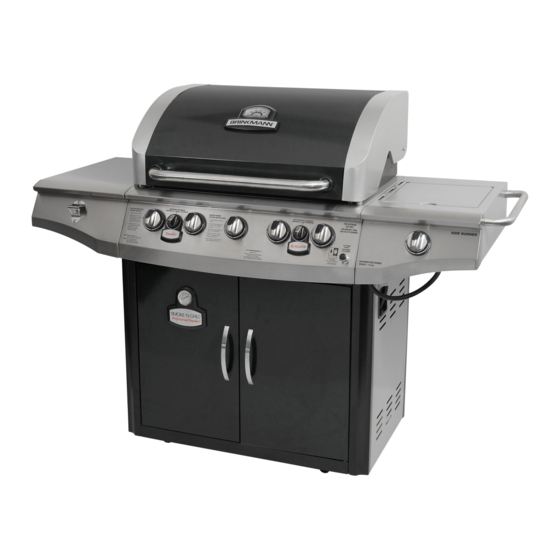
5 Burner Gas Grill with Smoker
Parrilla de Gas de 5 Quemadores
SAVE THIS MANUAL FOR FUTURE REFERENCE
GUARDE ESTE MANUAL PARA REFERENCIA FUTURA
NOTICE TO INSTALLER:
LEAVE THESE INSTRUCTIONS
WITH THE GRILL OWNER FOR
FUTURE REFERENCE .
AVISO PARA EL
INSTALADOR:
ENTREGUE ESTAS
INSTRUCCIONES AL
PROPIETARIO DE LA PARRILLA
PARA REFERENCIA FUTURA.
con el Ahumador
ASSEMBLY AND OPERATING IN STRUC TIONS
INSTRUCCIONES DE ARMADO Y OPERACIÓN
HAZARDOUS EXPLOSION MAY RESULT IF THESE WARNINGS AND INSTRUCTIONS
ARE IGNORED. READ AND FOLLOW ALL WARNINGS AND INSTRUCTIONS IN THIS
MANUAL TO AVOID PERSONAL INJURY, INCLUDING DEATH OR PROPERTY DAMAGE.
SE PUEDE PRODUCIR UNA EXPLOSIÓN PELIGROSA SI SE HACE CASO OMISO A
ESTAS ADVERTENCIAS E INSTRUCCIONES. LEA Y SIGA TODAS LAS ADVERTENCIAS
E INSTRUCCIONES EN ESTE MANUAL PARA EVITAR LESIONES PERSONALES,
400
300
206
500
262
150
318
600
200
94
374
38
700
430
100
800
WARNING/ADVERTENCIA
INCLUSO LA MUERTE, O LOS DAÑOS MATERIALES.
Advertisement
Chapters
Table of Contents

Related Manuals for Brinkmann Smoke'N Grill Professional


Summary of Contents for Brinkmann Smoke'N Grill Professional
- Page 1 5 Burner Gas Grill with Smoker Parrilla de Gas de 5 Quemadores con el Ahumador ASSEMBLY AND OPERATING IN STRUC TIONS INSTRUCCIONES DE ARMADO Y OPERACIÓN SAVE THIS MANUAL FOR FUTURE REFERENCE GUARDE ESTE MANUAL PARA REFERENCIA FUTURA WARNING/ADVERTENCIA NOTICE TO INSTALLER: HAZARDOUS EXPLOSION MAY RESULT IF THESE WARNINGS AND INSTRUCTIONS LEAVE THESE INSTRUCTIONS ARE IGNORED.
- Page 2 IMPORTANT SAFETY WARNINGS WE WANT YOU TO ASSEMBLE AND USE YOUR GRILL AS SAFELY AS POSSIBLE. THE PURPOSE OF THIS SAFETY ALERT SYMBOL IS TO ATTRACT YOUR ATTENTION TO POSSIBLE HAZARDS AS YOU ASSEMBLE AND USE YOUR GRILL. WHEN YOU SEE THE SAFETY ALERT SYMBOL PAY CLOSE ATTENTION TO THE INFORMATION WHICH FOLLOWS! READ ALL SAFETY WARNINGS AND INSTRUCTIONS CAREFULLY BEFORE ASSEMBLING AND OPERATING YOUR GRILL.
-
Page 3: Table Of Contents
TABLE OF CONTENTS: General Warnings ..........3-4 LP Gas Cylinder (Tank) Specifi cations and Installation . -
Page 4: General Warnings
GENERAL WARNINGS: WARNING • Leak test all connections before fi rst use, even if grill was purchased fully assembled and after each tank refi ll. Check the propane tank rubber seal for damage. • Always check the grill and propane tank prior to each use as indicated in the “Checking for Leaks” & “Pre-Start Check List”... -
Page 5: Lp Gas Cylinder (Tank) Specifications And Installation
• Grill is hot when in use. To avoid burns: • DO NOT attempt to move the grill. • Block the wheels so the unit does not accidentally move. • Wear protective gloves or oven mitts. • DO NOT touch any hot grill surfaces. •... - Page 6 LP GAS CYLINDER (TANK) SPECIFICATIONS: LP gas cylinder (not supplied with this grill) The LP (Liquid Propane) gas cylinder specifi cally designed to be used with this grill must be 12” (30.5 cm) diameter x 18” (45.7 cm) tall and have a 20 lb. (9.1 kg) capacity incorporating a Type 1 cylinder valve and an over-fi lling protection device (OPD).
-
Page 7: Hose & Regulator Specifications And Installation
• DO NOT attempt to connect grill, as purchased for LP (propane) gas, to any other fuel supply source such as a natural gas line. A Brinkmann conversion kit must be purchased and installed for use with natural gas. •... -
Page 8: Leak Testing
HOSE AND REGULATOR: Your grill is equipped with a Type 1 connection device with the following features: 1. The system will not allow gas fl ow from the cylinder until a positive connection to the valve has been made. Note: The cylinder valve and all grill burner knobs must be turned OFF before any connection is made or removed. -
Page 9: Checking For Leaks
DANGER To prevent fi re or explosion hazard: • DO NOT smoke or permit ignition sources in the area while conducting a leak test. • Perform test OUTDOORS in a well ventilated area that is protected from the wind. • Never perform a leak test with a match or open fl ame. -
Page 10: Pre-Start Check List
PRE-START CHECK LIST: DANGER Property damage, bodily harm, severe burns, and death could result from failure to follow these safety steps. These steps should be performed after the grill has been assembled and prior to each use. DO NOT operate this grill until you have read and understand ALL of the warnings and instructions in this manual. -
Page 11: Lighting The Side Burner
6. Repeat steps 3–5 for lighting each burner. Always use electronic igniter for lighting each burner. If burner does not ignite using the push-button igniter, see “Match Lighting the Main Burners” section. 7. To turn off, turn each control knob clockwise until it locks in the “OFF” position. This does not turn off the gas fl ow from the cylinder. -
Page 12: Lighting The Smoker
LIGHTING THE SMOKER: 1. Open door before lighting smoker burner. 2. Make sure control knob is in the “OFF” position. 3. Push and turn smoker burner control knob to the “HIGH” position and continue to push in. 4. Press the electronic igniter on the main control panel and hold for 3–5 seconds to light burner. -
Page 13: Operating The Grill
OPERATING THE GRILL: WARNING • Read and follow all warnings and instructions contained in the preceding sections of this manual. • Never use charcoal, lava rocks or wood briquets in a gas grill. Flavoring chips must be contained in a metal smoking box to contain ash and prevent fi res. •... -
Page 14: Using Other Features Of The Grill
ROTISSERIE COOKING: • Your grill was pre-drilled from the factory to include mounting holes for a rotisserie. Do not use a rotisserie not specifi cally manufactured for this grill. • Read and follow all instructions provided with the rotisserie. Save instructions for future reference. WARNING •... - Page 15 THE SIDE BURNER: • The side burner can be used to prepare side dishes such as beans, potatoes, corn, or to warm sauces. • The burner valve can be adjusted from high to low depending upon your cooking demands. THE SMOKER BOX: •...
-
Page 16: Proper Care And Maintenance
PROPER CARE & MAINTENANCE: WARNING: If a bristle brush is used to clean any of the cooking surfaces, ensure no loose bristles remain on the cooking surfaces prior to grilling as loose bristles may attach to food. CLEANING INTERIOR OF GRILL: •... - Page 17 BURNER ASSEMBLY/MAINTENANCE: • Although your burners are constructed of stainless steel, they may corrode as a result of the extreme heat and acids from cooking foods. Regularly inspect the burners for cracks, abnormal holes, and other signs of corrosion damage. If found, replace the burner.
-
Page 18: Transporting And Storage
BURNER ADJUSTMENT: WARNING • DO NOT attempt to adjust burner air shutter until grill has cooled down for approximately 30 minutes. Failure to do so could cause severe burns. • Normal fl ame should be soft blue with yellow tips between 1 in. - 2 in. when burner is on “HIGH”. Depending on elevation, burner air shutter may need to be adjusted to obtain correct air to fuel ratio. -
Page 19: Trouble Shooting
TROUBLE SHOOTING: To see trouble shooting or assembly videos, visit us at: Problem Possible Cause Prevention/Cure Burner will not light LP gas tank valve is closed Make sure regulator is securely attached to the LP gas tank, turn LP gas tank valve to “OPEN” LP gas tank is low or empty Check if LP gas tank is empty. -
Page 20: Grill Cooking Tips
Problem Possible Cause Prevention/Cure Flame blows out High or gusting winds Do not use grill in high winds Low on LP gas Replace or refi ll LP gas tank Burner holes may be obstructed Refer to “Burner Assembly/Maintenance” instructions Flow limiting device tripped Refer to “Regulator Resetting Procedure”... -
Page 21: Assembly Instructions
ASSEMBLY INSTRUCTIONS: Make sure you have all items listed under PARTS LIST and PARTS BAG CONTENTS before you begin the installation process. PARTS BAG CONTAINS: Qty. 10 M6 x 10 mm Bolts (Silver) M6 x 10 mm Bolts (Black) AA/1.5V Alkaline Battery M6 Nuts M6 x 10 mm Bolts (Silver) M6 x 10 mm Bolts (Black) - Page 22 READ ALL SAFETY WARNINGS & ASSEMBLY INSTRUCTIONS CAREFULLY BEFORE ASSEMBLING OR OPERATING YOUR GRILL. WE RECOMMEND TWO PEOPLE WORK TOGETHER WHEN AS SEM BLING THIS UNIT. ® The following tools are required to assemble this Brinkmann 5 Burner Gas Grill with Smoker: • Phillips Screwdriver PARTS LIST:...
- Page 23 FOR COVERS, ACCESSORIES AND OTHER PRODUCTS, PLEASE VISIT US ONLINE AT: (Proof of purchase will be required.) Inspect contents of the box to ensure all parts are included and undamaged.
- Page 24 Step 1 Attach left side table front panel to left side table using three M6 x 10 mm bolts. Tighten bolts securely. Step 2 Attach left side table to left side of grill body assembly. Place left side table keyholes over the pre- attached bolts and slide back.
- Page 25 Step 5 Attach side burner assembly to right side of grill body assembly. Place side burner assembly keyholes over the pre-attached bolts and slide back. Tighten securely. Fasten right side table front panel to grill body with one M6 x 10 mm bolt. Side Burner Venturi Burner...
- Page 26 Step 8 Attach side burner igniter lead wire to the electrode as illustrated. Side Burner Electrode Igniter Lead Step 9 Place the side burner grate onto the side burner table. Step 10 Support Racks Insert the support racks into the holes on the inside walls of the smoker.
- Page 27 Step 12 Place the wood chip pan and wood chip lid onto the center of the heat shield. Wood Chip Pan Lid Step 13 Wood Chip Place water pan onto water pan support. Heat Shield Water Support Rack Water Pan Support Smoker Cooking...
- Page 28 Warming Rack Step 17 Place the heat distribution plates on lower level of grill body Cooking Grills assembly directly above burners. Heat Distribution Step 18 Plates Place cooking grills on support ribs directly above heat distribution plates Step 19 Brackets Insert warming rack onto brackets so that it sits above the cooking grills.
- Page 29 Brinkmann ® 5 Burner Gas Grill & Smoker (Assembled)
-
Page 30: Rotisserie Warnings
ROTISSERIE WARNINGS: WARNING ELECTRICAL GROUNDING INSTRUCTIONS: This appliance (rotisserie motor) is equipped with a three-prong (grounding) plug for your protection against electrical shock hazard. It should be plugged directly into a properly grounded three-prong receptacle. DO NOT cut or remove the grounding prong from this plug. -
Page 31: Rotisserie Assembly Instructions
ROTISSERIE ASSEMBLY INSTRUCTIONS: Step 1 Open grill hood and remove cooking grills. Step 2 Attach rotisserie bracket A on the left hand side of the grill using two M6 x 10 mm bolts (black) and two M6 nuts. Step 3 Slide rotisserie motor onto the rotisserie bracket A. -
Page 32: Rotisserie Operating Instructions
ROTISSERIE OPERATING INSTRUCTIONS: WARNING ELECTRICAL GROUNDING INSTRUCTIONS: This appliance (rotisserie motor) is equipped with a three-prong (grounding) plug for your protection against electrical shock hazard. It should be plugged directly into a properly grounded three-prong receptacle. DO NOT cut or remove the grounding prong from this plug. - Page 33 IMPORTANTES ADVERTENCIAS DE SEGURIDAD ES NUESTRO DESEO QUE ARME Y UTILICE SU PARRILLA EN LA FORMA MÁS SEGURA POSIBLE. EL PROPÓSITO DE ESTE SÍMBOLO DE ALERTA DE SEGURIDAD ES QUE USTED PRESTE ATENCIÓN A LOS POSIBLES PELIGROS CUANDO ARME Y UTILICE SU PARRILLA. ¡CUÁNDO VEA ESTE SÍMBOLO DE ALERTA DE SEGURIDAD PRESTE ESPECIAL ATENCIÓN A LA INFORMACIÓN A CONTINUACIÓN!
- Page 34 TABLA DE CONTENIDOS: Advertencias Generales ........34-35 Especifi caciones e Instalación del Cilindro (Tanque) de Gas LP .
-
Page 35: Advertencias Generales
ADVERTENCIAS GENERALES: ADVERTENCIA • Antes de usar la parrilla por primera vez, pruebe todas las conexiones en busca de fugas, incluso si compró la parrilla totalmente armada y cada vez que vuelva a cargar el tanque. Inspeccione el sello de caucho del tanque de propano en busca de daños. -
Page 36: Especificaciones E Instalación Del Cilindro (Tanque) De Gas Lp
• Cacerola de agua siempre debe ser utilizado cuando se fuma. No permita que el líquido en la bandeja de agua se evapore completamente. Comprobar el agua cada 2 horas y agregar agua si el nivel es bajo (un sonido chisporroteante puede indicar la necesidad de agua). Siga las instrucciones de la sección “Adición de agua”... - Page 37 ESPECIFICACIONES DEL CILINDRO (TANQUE) DE GAS LP: Cilindro de gas LP (no suministrado con esta parrilla) El cilindro de gas LP (propano líquido) específi camente diseñado para usarse con esta parrilla debe tener 12” (30.5 cm) de diámetro × 18” (45.7 cm) de alto y una capacidad de 20 lb (9.1 kg), con una válvula del cilindro Tipo 1 y un dispositivo de protección contra sobrecarga (OPD).
-
Page 38: Especifi Caciones E Instalación De La Manguera Y El Regulador
INSPECCIÓN DEL SELLO DE CAUCHO DEL CILINDRO (TANQUE) DE GAS LP: • Antes de usar, inspeccione el sello de caucho de la válvula del tanque de propano en busca de fi suras, desgaste o signos de deterioro. Un sello de caucho dañado puede causar una fuga de gas, lo que posiblemente derive en una explosión, un incendio o lesiones corporales graves. -
Page 39: Pruebas De Detección De Fugas
REGULADOR Y MANGUERA: La parrilla viene equipada con un dispositivo de conexión Tipo 1 con las siguientes características: 1. El sistema no permitirá la circulación de gas desde el cilindro hasta que se establezca una conexión positiva a la válvula. Nota: La válvula del cilindro y todas las perillas de los quemadores de la parrilla deben estar cerradas antes de realizar o quitar cualquier conexión. - Page 40 PELIGRO Para prevenir los peligros vinculados con los incendios o explosiones: • NO fume ni permita que haya fuentes de ignición en la zona donde lleve a cabo una prueba de detección de fugas. • Realice la prueba en un área bien ventilada AL AIRE LIBRE, protegida contra el viento. •...
-
Page 41: Lista De Comprobación Previa Al Arranque
LISTA DE COMPROBACIÓN PREVIA AL ARRANQUE: PELIGRO Si no se siguen estos pasos, pueden ocurrir daños a la propiedad, lesiones corporales, quemaduras graves y la muerte. Estos pasos deben llevarse a cabo después de que la parrilla se armó y antes de cada uso. NO use esta parrilla hasta haber leído y entendido TODAS las advertencias y las instrucciones incluidas en este manual. -
Page 42: Encendido Del Quemador Lateral
7. Para apagar, gire cada perilla de control en sentido horario hasta que se trabe en la posición “APAGADO”. Esto no apaga el fl ujo de gas del cilindro. Nota: Si el quemador no se enciende o la llama es muy baja, consulte la sección “Solución de Problemas”... - Page 43 ENCENDIDO DEL AHUMADOR: 1. Abra la tapa antes de encender del ahumador. 2. Verifi que que todas las perillas de control estén en la posición “APAGADO”. 3. Presione y gire la perilla de control del quemador del ahumador hacia la posición “ALTO”...
-
Page 44: Funcionamiento De La Parrilla
ENCENDIDO DE LA HORNILLA DEL ASADOR ESTILO ROTISSERIE CON FÓSFOROS: 1. Abra la cubierta de la parrilla antes de encender la hornilla del asador estilo rotisserie. 2. Verifi que que la perilla de control esté en la posición “APAGADO”. 3. Prenda y coloque con cuidado un cerillo aproximadamente a 1/2 pulgada (1 a 2 cm) del borde inferior de la hornilla. -
Page 45: Apagado De La Parrilla
• Si ocurre un incendio de grasa con la tapa cerrada, deje la tapa cerrada, ya que una corriente de aire repentina puede aumentar las llamas. Coloque las perillas de los quemadores en la posición “APAGADO” y cierre la válvula del cilindro de gas LP. -
Page 46: Utilizando Otras Funciones De La Parrilla
USO DE OTRAS FUNCIONES DE LA PARRILLA: ADVERTENCIA • Lea las instrucciones de encendido de la parrilla para encender el quemador lateral. • Nunca cierre la cubierta del quemador lateral cuando el quemador esté encendido. • Cuando cocine en el quemador lateral, use una olla de 10” de diámetro o más pequeña SIN un mango extendido. -
Page 47: Cuidado Y Mantenimiento Adecuados
PRECAUCION: La bandeja para astillas de madera/agua y su cubierta pueden calentarse mucho. Procure no tocarlas durante el uso. Siempre póngase guantes gruesos de cocina antes de tocar partes calientes Recomendaciones de cocimiento – Leña para dar sabor: • Los pedacitos de leña imparten mejor sabor si se dejan dentro de la caja. •... - Page 48 ÓXIDO: • Como resultado de las altas temperaturas de cocción, los adobos ácidos, los incendios de grasa, y la exposición a climas costeros u a otros elementos naturales, puede observarse decoloración, óxido o picaduras de óxido. • Las manchas de óxido en la superfi cie interior se pueden pulir, limpiar y cubrir ligeramente con aceite vegetal o con aceite vegetal en aerosol para minimizar la oxidación.
- Page 49 CONJUNTO DE LOS QUEMADORES/ MANTENIMIENTO: • Si bien los quemadores están hechos de acero inoxidable, pueden corroerse como resultado del calor extremo y de los ácidos derivados de la cocción de comida. Periódicamente, inspeccione los quemadores en busca de fi suras, orifi cios anormales y otros signos de deterioro por corrosión.
-
Page 50: Transporte Y Almacenamiento
AJUSTE DE LOS QUEMADORES: ADVERTENCIA • NO intente ajustar el obturador de aire de los quemadores hasta que la parrilla se haya enfriado durante aproximadamente 30 minutos. Si no cumple con esta indicación, puede sufrir quemaduras graves. • Las llamas normales deben ser de color azul claro con puntas amarillas, y deben ser de entre 1” y 2” cuando el quemador está... -
Page 51: Solución De Problemas
SOLUCIÓN DE PROBLEMAS: Para ver videos de montaje o solución de problemas, visítenos en: Problema Causa posible Prevención/Cuidado El quemador no enciende La válvula del tanque de gas LP está cerrada Cerciórese de que el regulador esté conectado al tanque de gas LP con fi rmeza;... - Page 52 Problema Causa posible Prevención/Cuidado La llama es amarilla o Es posible que el quemador nuevo contenga Encienda la parrilla durante 15 minutos en la posición “ALTO” con la anaranjada aceites residuales de la fabricación tapa cerrada Es posible que haya telarañas o nidos Limpie el conjunto de los quemadores y los tubos venturi de los de insectos en los tubos venturi de los quemadores...
-
Page 53: Sugerencias Para Cocinar Con La Parrilla
SUGERENCIAS PARA COCINAR CON LA PARRILLA: HIGIENE: • Siempre lávese las manos minuciosamente con jabón y agua caliente antes de manipular la comida y después de manipular carne vacuna o de pollo cruda, o mariscos/pescados. • Cuando use una fuente para transportar carne vacuna o de pollo cruda, o mariscos/pescado hasta la parrilla, asegúrese de lavar la fuente minuciosamente con jabón y agua caliente antes de colocar la comida cocida en dicha fuente, o use fuentes diferentes para los alimentos crudos y la comida cocida. -
Page 54: Instrucciones De Armado
INSTRUCCIONES DE ARMADO: Verifi que que tiene todos los artículos indicados en la LISTA DE PARTES y en el CONTENIDO DE LA BOLSA DE PARTES antes de comenzar con el proceso de instalación. LA BOLSA DE PARTES INCLUIRÁ LO SIGUIENTE: Cant. - Page 55 E INSTRUCCIONES ANTES DE ARMAR Y USAR LA PARRILLA RECOMENDAMOS QUE ESTA UNIDAD SEA ARMADA POR DOS PERSONAS ® Se necesitan las siguientes herramientas para armar esta Brinkmann Parrilla de Gas de 5 Hornillas con el Ahumador: • Destornillador de punta Phillips...
- Page 56 PARA CUBIERTAS, ACCESORIOS Y OTROS PRODUCTOS, FAVOR DE VISITARNOS POR LA RED MUNDIAL EN: (La prueba de compra se requiere.) Inspeccione el contenido de la caja para verifi car que todas las partes estén incluidas e intactas.
- Page 57 Paso 1 Sujete el panel frontal de la mesa lateral izquierda a la mesa lateral izquierda, utilizando tres pernos M6 x 10 mm. Ajuste los pernos fi rmemente. Paso 2 Fije la mesa lateral izquierda al lado izquierdo del montaje del cuerpo de la parrilla.
- Page 58 Paso 5 Fije el montaje del quemador lateral al lateral derecho del montaje del cuerpo de la parrilla. Coloque las perforaciones de montaje del quemador lateral sobre los pernos previamente colocados y deslice hacia atrás. Ajuste el perno fi rmemente. Fije el panel frontal de la mesa lateral derecha al cuerpo de la parrilla con un perno M6 x 10 mm.
- Page 59 Paso 8 Conecte el cable conductor del encendedor de la hornilla lateral al electrodo, tal como se ilustra. Conductor del Encendedor de la Hornilla Electrodo Lateral Paso 9 Coloque la rejilla de la hornilla lateral sobre la mesa de la hornilla lateral.
- Page 60 Paso 12 Luego pon la bandeja se chips de Tapa de la madera y la tapa de la bandeja de Bandeja para protector de calor. Astillas de Madera Paso 13 Bandeja Coloque la bandeja de agua en el de Chips soporte la bandeja de agua.
- Page 61 Paso 17 Rejilla para Coloque las placas de distribución Calentar de calor en el nivel inferior de la caja de la parrilla, directamente sobre las hornillas. Rejilla para Cocinar Paso 18 Placas de Distribución Coloque las rejillas para cocinar de de Calor hierro fundido revestido sobre las costillas de apoyo directamente sobre...
- Page 62 ® Brinkmann Parrilla de Gas de 5 Hornillas con el Ahumador (Armada)
-
Page 63: Advertencias Del Asador
ADVERTENCIAS DEL ASADOR: ADVERTENCIA INSTRUCCIONES PARA CONECTAR A TIERRA LOS ARTEFACTOS ELÉCTRICOS: Este artefacto (motor del asador estilo rotisserie) está equipado con un enchufe de tres clavijas (de puesta a tierra) para proteger al usuario contra el electrochoque. Este enchufe debe conectarse directamente a un receptáculo para tres clavijas conectado correctamente a tierra. -
Page 64: Instrucciones De Armado Del Asador
INSTRUCCIONES DE ARMADO DEL ASADOR: Paso 1 Abra la cubierta de la parrilla y quite las rejillas para cocinar. Paso 2 Instale el soporte A del asador en el lado izquierdo de la parrilla con dos pernos M6 x 10 mm (negros) y dos tuercas M6. -
Page 65: Funcionamiento Del Asador
INSTRUCCIONES DE FUNCIONAMIENTO DEL ASADOR: ADVERTENCIA INSTRUCCIONES PARA CONECTAR A TIERRA LOS ARTEFACTOS ELÉCTRICOS: Este artefacto (motor del asador estilo rotisserie) está equipado con un enchufe de tres clavijas (de puesta a tierra) para proteger al usuario contra el electrochoque. Este enchufe debe conectarse directamente a un receptáculo para tres clavijas conectado correctamente a tierra. - Page 66 This warranty extends to the original purchaser only and is not trans fer able or assignable to subsequent purchasers. The Brinkmann Corporation requires reasonable proof of purchase. Therefore, we strongly recommend that you retain your sales receipt or invoice. To ®...