Table of Contents
Advertisement
Quick Links
Features
1
2
3
4
5
6
7 8
9
24
23
22
21
20
19
18
17
16
15
Printed in China.
UPMIDIAS
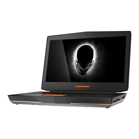
Features
Fonctionnalités
Funciones
1.
Left digital-array microphone
1.
Microphone numérique
1.
Micrófono del arreglo
de gauche
digital izquierdo
Camera
2.
2.
Appareil photo
2.
Cámara
Camera-status light
3.
Voyant d'état de la caméra
Indicador del estado de
Right digital-array microphone
3.
3.
4.
la cámara
Microphone numérique
4.
5.
Power button
de droite
Micrófono del arreglo
4.
Power-status light
6.
digital derecho
Bouton d'alimentation
5.
Hard-drive activity light
7.
5.
Botón de encendido
Voyant d'état de
6.
Wireless-status light
8.
l'alimentation
Indicador luminoso de estado
6.
Caps-lock status light
9.
de la alimentación
Voyant d'activité du disque dur
7.
Network port
10.
Indicador luminoso de actividad
Voyant d'état du sans fil
7.
8.
USB 3.0 port
de la unidad del disco duro
11.
Voyant de statut
9.
Indicador del estado de la
12.
USB 3.0 port with PowerShare
des majuscules
8.
conexión inalámbrica
Optical drive, hard drive,
13.
10.
Port réseau
or solid-state drive
Luz de Bloq Mayús
9.
Port USB 3.0
11.
Puerto de red
Media-card reader
10.
14.
Port USB 3.0 avec PowerShare
12.
Puerto USB 3.0
Backlit keyboard
11.
15.
Lecteur optique, disque dur,
13.
Backlit touchpad
12.
Puerto USB 3.0 con PowerShare
16.
ou lecteur SSD
Unidad óptica, unidad de disco
17.
Headphones and microphone
Lecteur de carte média
13.
14.
duro, o unidad de estado sólido
combo port
15.
Clavier rétro-éclairé
Headphones/Speakers port
Lector de tarjetas multimedia
18.
14.
Tablette tactile rétro-éclairée
16.
Teclado retroiluminado
Microphone port
15.
19.
Port pour combiné
17.
Panel táctil retroiluminado
USB 3.0 ports (2)
16.
20.
casque/microphone
Mini DisplayPort
17.
Un puerto combo de
21.
Port casque/hauts-parleur
18.
audífono/micrófono
22.
HDMI In/Out port
Port microphone
19.
Puerto de audífonos/altavoces
18.
Power-adapter port
23.
20.
Ports USB 3.0 (2)
10
Puerto del micrófono
19.
Security-cable slot
11
24.
Port Mini Display
21.
Puertos USB 3.0 (2)
20.
12
Port entrée/sortie HDMI
22.
Mini-DisplayPort
21.
Port de l'adaptateur secteur
23.
Puerto de entrada/salida HDMI
22.
24.
Fente pour câble de sécurité
Puerto de adaptador
23.
13
de alimentación
24.
Ranura del cable de seguridad
14
More Information
En savoir plus
Más Información
For the latest information, FAQs,
Pour vous mettre au courant des dernières
Para información reciente, respuestas
and solutions to most common issues,
informations, consulter les FAQ et découvrir
a preguntas frecuentes y soluciones
les solutions aux problèmes les plus usuels,
see dell.com/Alienware
a problemas comunes, visite dell.com/Alienware
reportez-vous à dell.com/Alienware
For sales, technical support, or customer
Para ventas, soporte técnico, o asuntos de
Pour des questions commerciales, de support
service issues, see dell.com/ContactDell
atención al cliente, consulte dell.com/ContactDell
technique ou de service après-vente, visitez
© 2013 Dell Inc.
le site dell.com/ContactDell
© 2013 Dell Inc.
Alienware™, AlienFX™, and the AlienHead logo
Alienware™, AlienFX™, y el logotipo AlienHead
© 2013 Dell Inc.
are trademarks or registered trademarks of
son marcas comerciales o marcas comerciales
Alienware™, AlienFX™ et le logo AlienHead sont
Alienware Corporation. Dell™ is a trademark
registradas de Alienware Corporation; Dell™ es
des marques commerciales ou des marques
of Dell Inc.
una marca comercial de Dell Inc.
déposées d'Alienware Corporation. Dell™ est
une marque commerciale de Dell Inc.
2013 - 04
2013 - 04
2013 - 04
Regulatory model: P19E
|
Type: P19E001
Modelo normativo: P19E
Computer model: Alienware 18 R1
Modèle réglementaire : P19E
|
Type : P19E001
Modelo de equipo: Alienware 18 R1
Modèle de l'ordinateur : Alienware 18 R1
|
Tipo: P19E001
18
Quick Start Guide
Guide d'information rapide | Guía de inicio rápido
Advertisement
Table of Contents

Related Manuals for Alienware Alienware 18 P19E


Summary of Contents for Alienware Alienware 18 P19E
- Page 1 © 2013 Dell Inc. are trademarks or registered trademarks of son marcas comerciales o marcas comerciales Alienware™, AlienFX™ et le logo AlienHead sont Guide d’information rapide | Guía de inicio rápido Alienware Corporation. Dell™ is a trademark registradas de Alienware Corporation; Dell™ es des marques commerciales ou des marques of Dell Inc.
- Page 2 Change le port HDMI en entrée ou en sortie input and output Cambiar HDMI entre entrada y salida Launch/close Alienware Lance/ferme le contrôle de performance Alienware Press the power button Performance Monitoring Lanzar/cerrar Monitoreo de Rendimiento Alienware Appuyez sur le bouton d’alimentation | Presione el botón de encendido Disable/enable touchpad Désactive/active la tablette tactile...
- Page 3 Alienware 18 Owner’s Manual UPMIDIAS Computer model: Alienware 18 Regulatory model: P19E Regulatory type: P19E001...
- Page 4 Reproduction of these materials in any manner whatsoever without the written permission of Dell Inc. is strictly forbidden. Trademarks used in this text: Alienware™ and the AlienHead logo are trademarks or registered trademarks of Alienware Corporation; Dell™ is a trademark of Dell Inc.;...
-
Page 5: Table Of Contents
Contents Before You Begin ......Turn Off Your Computer and Connected Devices . - Page 6 Removing the Hard Drive(s) ..... Prerequisites ......Procedure .
- Page 7 Removing the Palm Rest ..... . . Prerequisites ......Procedure .
- Page 8 Removing the Macro Keyboard ....Prerequisites ......Procedure .
- Page 9 Removing the Display Panel ..... Prerequisites ......Procedure .
- Page 10 Removing the Sound Board ..... Prerequisites ......Procedure .
- Page 11 Removing the System Board ..... Prerequisites ......Procedure .
- Page 12 UPMIDIAS Contents...
-
Page 13: Before You Begin
Before You Begin Turn Off Your Computer and Connected Devices CAUTION: To avoid losing data, save and close all open files and exit all open programs before you turn off your computer. Save and close all open files and exit all open programs. Follow the instructions to shut down your computer based on the operating system installed on your computer. -
Page 14: Safety Instructions
Safety Instructions Use the following safety guidelines to protect your computer from potential damage and ensure your personal safety. WARNING: Disconnect all power sources before opening the computer cover or panels. After you finish working inside the computer, replace all covers, panels, and screws before connecting to the power source. -
Page 15: After Working Inside Your Computer
After Working Inside Your Computer After you complete the replacement procedures, ensure the following: • Replace all screws and ensure that no stray screws remain inside your computer • Connect any external devices, cables, cards, and any other part(s) you removed before working on your computer •... -
Page 16: Removing The Base Cover
Removing the Base Cover WARNING: Before working inside your computer, read the safety information that shipped with your computer and follow the steps in "Before You Begin" on page 11. For additional safety best practices information, see the Regulatory Compliance Homepage at dell.com/regulatory_compliance. -
Page 17: Replacing The Base Cover
Replacing the Base Cover WARNING: Before working inside your computer, read the safety information that shipped with your computer and follow the steps in "Before You Begin" on page 11. For additional safety best practices information, see the Regulatory Compliance Homepage at dell.com/regulatory_compliance. -
Page 18: Removing The Battery Pack
Removing the Battery Pack WARNING: Before working inside your computer, read the safety information that shipped with your computer and follow the steps in "Before You Begin" on page 11. For additional safety best practices information, see the Regulatory Compliance Homepage at dell.com/regulatory_compliance. -
Page 19: Replacing The Battery Pack
CAUTION: To avoid damage to the computer, use only the battery designed for this particular Alienware computer. Procedure Align the tabs on the battery with the slots on the computer base and place the battery on the computer base. -
Page 20: Removing The Memory Module(S)
Removing the Memory Module(s) WARNING: Before working inside your computer, read the safety information that shipped with your computer and follow the steps in "Before You Begin" on page 11. For additional safety best practices information, see the Regulatory Compliance Homepage at dell.com/regulatory_compliance. -
Page 21: Procedure
Procedure To remove memory module(s) from connectors DIMM3 and DIMM4, go to step 3. To remove memory module(s) from connectors DIMM1 and DIMM2: Remove the palm rest. See "Removing the Palm Rest" on page 39. CAUTION: To prevent damage to the memory-module connector, do not use tools to spread the memory module securing clips. -
Page 22: Replacing The Memory Module(S)
Replacing the Memory Module(s) WARNING: Before working inside your computer, read the safety information that shipped with your computer and follow the steps in "Before You Begin" on page 11. For additional safety best practices information, see the Regulatory Compliance Homepage at dell.com/regulatory_compliance. -
Page 23: Postrequisites
If you have replaced memory module(s) in connectors DIMM3 and DIMM4, go to Postrequisites. If you have replaced memory module(s) in connectors DIMM1 and DIMM2: Replace the palm rest. See "Replacing the Palm Rest" on page 42. Postrequisites Replace the battery pack. See "Replacing the Battery Pack" on page 17. Replace the base cover. -
Page 24: Removing The Optical Drive
Removing the Optical Drive WARNING: Before working inside your computer, read the safety information that shipped with your computer and follow the steps in "Before You Begin" on page 11. For additional safety best practices information, see the Regulatory Compliance Homepage at dell.com/regulatory_compliance. - Page 25 Remove the screws that secure the optical-drive bracket to the optical drive. Lift the optical-drive bracket off the optical drive. UPMIDIAS optical-drive bracket interposer screws (4) Remove the interposer from the optical drive. Removing the Optical Drive...
-
Page 26: Replacing The Optical Drive
Replacing the Optical Drive WARNING: Before working inside your computer, read the safety information that shipped with your computer and follow the steps in "Before You Begin" on page 11. For additional safety best practices information, see the Regulatory Compliance Homepage at dell.com/regulatory_compliance. -
Page 27: Removing The Hard Drive(S)
Removing the Hard Drive(s) WARNING: Before working inside your computer, read the safety information that shipped with your computer and follow the steps in "Before You Begin" on page 11. For additional safety best practices information, see the Regulatory Compliance Homepage at dell.com/regulatory_compliance. -
Page 28: Procedure
Procedure Disconnect the hard-drive cable from its connector on the system board. Loosen the captive screws that secure the hard-drive assembly to the computer base. Using the pull-tab, lift the hard-drive assembly out of the computer base. UPMIDIAS hard-drive cable captive screws (4) pull tab hard drive... - Page 29 Disconnect the interposer from the hard drives. NOTE: Your computer supports up to three drives. Remove the screws that secure the hard drive(s) to the hard-drive bracket and slide the hard drive(s) out of the hard-drive bracket. UPMIDIAS hard drive interposer screws (4) Removing the Hard Drive(s)
-
Page 30: Replacing The Hard Drive(S)
Replacing the Hard Drive(s) WARNING: Before working inside your computer, read the safety information that shipped with your computer and follow the steps in "Before You Begin" on page 11. For additional safety best practices information, see the Regulatory Compliance Homepage at dell.com/regulatory_compliance. -
Page 31: Removing The Fans Cover
Removing the Fans Cover WARNING: Before working inside your computer, read the safety information that shipped with your computer and follow the steps in "Before You Begin" on page 11. For additional safety best practices information, see the Regulatory Compliance Homepage at dell.com/regulatory_compliance. -
Page 32: Replacing The Fans Cover
Replacing the Fans Cover WARNING: Before working inside your computer, read the safety information that shipped with your computer and follow the steps in "Before You Begin" on page 11. For additional safety best practices information, see the Regulatory Compliance Homepage at dell.com/regulatory_compliance. -
Page 33: Removing The Video-Card Heat-Sink Fan(S)
Removing the Video-Card Heat-Sink Fan(s) WARNING: Before working inside your computer, read the safety information that shipped with your computer and follow the steps in "Before You Begin" on page 11. For additional safety best practices information, see the Regulatory Compliance Homepage at dell.com/regulatory_compliance. - Page 34 Disconnect the secondary video-card heat-sink fan cable from its connector on the system board. Loosen the captive screws that secure the secondary video-card heat-sink fan to the computer base. UPMIDIAS captive screws (4) secondary video-card heat-sink fan secondary video-card heat-sink fan cable Lift the video-card heat-sink fan(s) along with the cable away from the computer base.
-
Page 35: Replacing The Video-Card Heat-Sink Fan(S)
Replacing the Video-Card Heat-Sink Fan(s) WARNING: Before working inside your computer, read the safety information that shipped with your computer and follow the steps in "Before You Begin" on page 11. For additional safety best practices information, see the Regulatory Compliance Homepage at dell.com/regulatory_compliance. -
Page 36: Removing The Processor Heat-Sink Fan
Removing the Processor Heat-Sink Fan WARNING: Before working inside your computer, read the safety information that shipped with your computer and follow the steps in "Before You Begin" on page 11. For additional safety best practices information, see the Regulatory Compliance Homepage at dell.com/regulatory_compliance. -
Page 37: Replacing The Processor Heat-Sink Fan
Replacing the Processor Heat-Sink Fan WARNING: Before working inside your computer, read the safety information that shipped with your computer and follow the steps in "Before You Begin" on page 11. For additional safety best practices information, see the Regulatory Compliance Homepage at dell.com/regulatory_compliance. -
Page 38: Removing The Coin-Cell Battery
Removing the Coin-Cell Battery WARNING: Before working inside your computer, read the safety information that shipped with your computer and follow the steps in "Before You Begin" on page 11. For additional safety best practices information, see the Regulatory Compliance Homepage at dell.com/regulatory_compliance. -
Page 39: Procedure
Procedure Disconnect the coin-cell battery cable from its connector on the system board. UPMIDIAS coin-cell battery cable connector coin-cell battery Remove the coin-cell battery cable from the routing guides on the computer base. Pry up the coin-cell battery from the slot on the system board. Removing the Coin-Cell Battery... -
Page 40: Replacing The Coin-Cell Battery
Replacing the Coin-Cell Battery WARNING: Before working inside your computer, read the safety information that shipped with your computer and follow the steps in "Before You Begin" on page 11. For additional safety best practices information, see the Regulatory Compliance Homepage at dell.com/regulatory_compliance. -
Page 41: Removing The Palm Rest
Removing the Palm Rest WARNING: Before working inside your computer, read the safety information that shipped with your computer and follow the steps in "Before You Begin" on page 11. For additional safety best practices information, see the Regulatory Compliance Homepage at dell.com/regulatory_compliance. -
Page 42: Procedure
Procedure Lift the connector latches and pull the pull-tabs to disconnect the media-card reader cable and keyboard cable from the connectors on the palm-rest assembly. Lift the connector latches and pull the pull-tabs to disconnect the macro-keyboard cable and macro-keyboard backlight cable from the connectors on the system board. Remove the screws that secure the palm-rest assembly to the computer base. - Page 43 Turn the computer over. Carefully pry out the palm-rest assembly from the two tabs along the rear edge of the computer, and then ease the palm-rest assembly from the computer base. CAUTION: Carefully separate the palmrest from the computer base to avoid damage to the palmrest.
-
Page 44: Replacing The Palm Rest
Replacing the Palm Rest WARNING: Before working inside your computer, read the safety information that shipped with your computer and follow the steps in "Before You Begin" on page 11. For additional safety best practices information, see the Regulatory Compliance Homepage at dell.com/regulatory_compliance. -
Page 45: Removing The Msata Card
Removing the mSATA Card WARNING: Before working inside your computer, read the safety information that shipped with your computer and follow the steps in "Before You Begin" on page 11. For additional safety best practices information, see the Regulatory Compliance Homepage at dell.com/regulatory_compliance. -
Page 46: Replacing The Msata Card
Replacing the mSATA Card WARNING: Before working inside your computer, read the safety information that shipped with your computer and follow the steps in "Before You Begin" on page 11. For additional safety best practices information, see the Regulatory Compliance Homepage at dell.com/regulatory_compliance. -
Page 47: Removing The Power-Button Board
Removing the Power-Button Board WARNING: Before working inside your computer, read the safety information that shipped with your computer and follow the steps in "Before You Begin" on page 11. For additional safety best practices information, see the Regulatory Compliance Homepage at dell.com/regulatory_compliance. -
Page 48: Replacing The Power-Button Board
Replacing the Power-Button Board WARNING: Before working inside your computer, read the safety information that shipped with your computer and follow the steps in "Before You Begin" on page 11. For additional safety best practices information, see the Regulatory Compliance Homepage at dell.com/regulatory_compliance. -
Page 49: Removing The Status-Light Board
Removing the Status-Light Board WARNING: Before working inside your computer, read the safety information that shipped with your computer and follow the steps in "Before You Begin" on page 11. For additional safety best practices information, see the Regulatory Compliance Homepage at dell.com/regulatory_compliance. -
Page 50: Procedure
Procedure Lift the connector latches and pull the pull-tabs to disconnect the power-button board cable and media-card reader cable from the connectors on the status-light board. Remove the screws that secure the status-light board to the palm-rest assembly. UPMIDIAS screws (2) power-button board cable status-light board media-card reader cable... -
Page 51: Replacing The Status-Light Board
Replacing the Status-Light Board WARNING: Before working inside your computer, read the safety information that shipped with your computer and follow the steps in "Before You Begin" on page 11. For additional safety best practices information, see the Regulatory Compliance Homepage at dell.com/regulatory_compliance. -
Page 52: Removing The Keyboard
Removing the Keyboard WARNING: Before working inside your computer, read the safety information that shipped with your computer and follow the steps in "Before You Begin" on page 11. For additional safety best practices information, see the Regulatory Compliance Homepage at dell.com/regulatory_compliance. -
Page 53: Procedure
Procedure Remove the screws that secure the keyboard-bracket to the keyboard. CAUTION: The keycaps on the keyboard are fragile, easily dislodged, and time-consuming to replace. Be careful when removing and handling the keyboard. CAUTION: Be extremely careful when removing and handling the keyboard. - Page 54 Lift the connector latch and pull the pull-tab to disconnect the keyboard cable from the respective connector. Remove the screws that secure the keyboard to the palm-rest assembly. UPMIDIAS screws (2) keyboard cable Lift the keyboard off the palm-rest assembly. Removing the Keyboard...
-
Page 55: Replacing The Keyboard
Replacing the Keyboard WARNING: Before working inside your computer, read the safety information that shipped with your computer and follow the steps in "Before You Begin" on page 11. For additional safety best practices information, see the Regulatory Compliance Homepage at dell.com/regulatory_compliance. -
Page 56: Removing The Macro Keyboard
Removing the Macro Keyboard WARNING: Before working inside your computer, read the safety information that shipped with your computer and follow the steps in "Before You Begin" on page 11. For additional safety best practices information, see the Regulatory Compliance Homepage at dell.com/regulatory_compliance. -
Page 57: Replacing The Macro Keyboard
Replacing the Macro Keyboard WARNING: Before working inside your computer, read the safety information that shipped with your computer and follow the steps in "Before You Begin" on page 11. For additional safety best practices information, see the Regulatory Compliance Homepage at dell.com/regulatory_compliance. -
Page 58: Removing The Display Assembly
Removing the Display Assembly WARNING: Before working inside your computer, read the safety information that shipped with your computer and follow the steps in "Before You Begin" on page 11. For additional safety best practices information, see the Regulatory Compliance Homepage at dell.com/regulatory_compliance. - Page 59 Turn the computer over and open the display. Disconnect the video-card connector cable from its connector on the system board. Pull the pull-tab to disconnect the display cable from its connector on the system board. Disconnect the LED-logo board cable from its connector on the system board. UPMIDIAS display cable connector LED logo-board cable...
- Page 60 Disconnect the antenna cables from the connectors on the Mini-Card. See "Removing the Wireless Mini-Card" on page 105. Note the routing of the antenna cables, and then remove the cables from the routing guides on the computer base. Remove the screw that secures the routing guides to the computer base. Slide and lift the routing guides off the computer base.
- Page 61 Remove the screws, on the display hinges, that secure the display assembly to the computer base. Move the display to a perpendicular position to the computer base, and then lift the display assembly off the computer. UPMIDIAS display assembly screws (3) Removing the Display Assembly...
-
Page 62: Replacing The Display Assembly
Replacing the Display Assembly WARNING: Before working inside your computer, read the safety information that shipped with your computer and follow the steps in "Before You Begin" on page 11. For additional safety best practices information, see the Regulatory Compliance Homepage at dell.com/regulatory_compliance. -
Page 63: Removing The Camera Module
Removing the Camera Module WARNING: Before working inside your computer, read the safety information that shipped with your computer and follow the steps in "Before You Begin" on page 11. For additional safety best practices information, see the Regulatory Compliance Homepage at dell.com/regulatory_compliance. -
Page 64: Procedure
Procedure Remove the screw that secures the camera module to the display back-cover. Disconnect the camera cable from the camera-module connector. Pry and lift the camera module off the display back-cover. UPMIDIAS screw (1) camera module camera-cable connector Removing the Camera Module... -
Page 65: Replacing The Camera Module
Replacing the Camera Module WARNING: Before working inside your computer, read the safety information that shipped with your computer and follow the steps in "Before You Begin" on page 11. For additional safety best practices information, see the Regulatory Compliance Homepage at dell.com/regulatory_compliance. -
Page 66: Removing The Display Bezel
Removing the Display Bezel WARNING: Before working inside your computer, read the safety information that shipped with your computer and follow the steps in "Before You Begin" on page 11. For additional safety best practices information, see the Regulatory Compliance Homepage at dell.com/regulatory_compliance. -
Page 67: Replacing The Display Bezel
Replacing the Display Bezel WARNING: Before working inside your computer, read the safety information that shipped with your computer and follow the steps in "Before You Begin" on page 11. For additional safety best practices information, see the Regulatory Compliance Homepage at dell.com/regulatory_compliance. -
Page 68: Removing The Display Hinges
Removing the Display Hinges WARNING: Before working inside your computer, read the safety information that shipped with your computer and follow the steps in "Before You Begin" on page 11. For additional safety best practices information, see the Regulatory Compliance Homepage at dell.com/regulatory_compliance. -
Page 69: Replacing The Display Hinges
Replacing the Display Hinges WARNING: Before working inside your computer, read the safety information that shipped with your computer and follow the steps in "Before You Begin" on page 11. For additional safety best practices information, see the Regulatory Compliance Homepage at dell.com/regulatory_compliance. -
Page 70: Removing The Display Panel
Removing the Display Panel WARNING: Before working inside your computer, read the safety information that shipped with your computer and follow the steps in "Before You Begin" on page 11. For additional safety best practices information, see the Regulatory Compliance Homepage at dell.com/regulatory_compliance. -
Page 71: Procedure
Procedure Remove the screws that secure the display panel to the display back-cover. Lift the display panel off the display back-cover. UPMIDIAS screws (8) display panel Removing the Display Panel... - Page 72 Turn the display panel over and place it on a clean surface. Peel the tape that secures the display cable to the display-panel connector. Lift the connector latch and disconnect the display cable from the display-panel connector. Lift the display cable off the display panel. UPMIDIAS tape display cable...
- Page 73 Remove the screws that secure the display-panel brackets to the display panel. Slide the display-panel brackets off the display panel. UPMIDIAS screws (6) display-panel brackets display panel Removing the Display Panel...
-
Page 74: Replacing The Display Panel
Replacing the Display Panel WARNING: Before working inside your computer, read the safety information that shipped with your computer and follow the steps in "Before You Begin" on page 11. For additional safety best practices information, see the Regulatory Compliance Homepage at dell.com/regulatory_compliance. -
Page 75: Removing The Logo Board
Removing the Logo Board WARNING: Before working inside your computer, read the safety information that shipped with your computer and follow the steps in "Before You Begin" on page 11. For additional safety best practices information, see the Regulatory Compliance Homepage at dell.com/regulatory_compliance. -
Page 76: Procedure
Procedure Remove the screws that secure the logo board to the display back-cover. Carefully rotate the logo board over and disconnect the display-light board cables from the connectors on the logo board. Lift the logo board off the display back-cover. UPMIDIAS screws (2) logo board... -
Page 77: Replacing The Logo Board
Replacing the Logo Board WARNING: Before working inside your computer, read the safety information that shipped with your computer and follow the steps in "Before You Begin" on page 11. For additional safety best practices information, see the Regulatory Compliance Homepage at dell.com/regulatory_compliance. -
Page 78: Removing The Display-Light Boards
Removing the Display-Light Boards WARNING: Before working inside your computer, read the safety information that shipped with your computer and follow the steps in "Before You Begin" on page 11. For additional safety best practices information, see the Regulatory Compliance Homepage at dell.com/regulatory_compliance. -
Page 79: Procedure
Procedure Remove the screws that secure the display-light boards to the display back-cover. Lift the display-light boards off the display back-cover. UPMIDIAS screws (5) display-light boards (3) Removing the Display-Light Boards... -
Page 80: Replacing The Display-Light Boards
Replacing the Display-Light Boards WARNING: Before working inside your computer, read the safety information that shipped with your computer and follow the steps in "Before You Begin" on page 11. For additional safety best practices information, see the Regulatory Compliance Homepage at dell.com/regulatory_compliance. -
Page 81: Removing The Speakers
Removing the Speakers WARNING: Before working inside your computer, read the safety information that shipped with your computer and follow the steps in "Before You Begin" on page 11. For additional safety best practices information, see the Regulatory Compliance Homepage at dell.com/regulatory_compliance. -
Page 82: Procedure
Procedure Disconnect the speakers cable from its connector on the system board. Note the speakers cable routing and remove the cable from the routing guides on the computer base. Remove the screws that secure the speakers to the computer base. Lift the speakers, along with the speaker cable, off the computer base. -
Page 83: Replacing The Speakers
Replacing the Speakers WARNING: Before working inside your computer, read the safety information that shipped with your computer and follow the steps in "Before You Begin" on page 11. For additional safety best practices information, see the Regulatory Compliance Homepage at dell.com/regulatory_compliance. -
Page 84: Removing The Subwoofer
Removing the Subwoofer WARNING: Before working inside your computer, read the safety information that shipped with your computer and follow the steps in "Before You Begin" on page 11. For additional safety best practices information, see the Regulatory Compliance Homepage at dell.com/regulatory_compliance. -
Page 85: Procedure
Procedure Disconnect the subwoofer cable from its connector on the system board. Note the subwoofer-cable routing and remove the cable from the routing guides on the computer base. Loosen the captive screws that secure the subwoofer to the computer base. Lift the subwoofer, along with the subwoofer cable, off the computer base. -
Page 86: Replacing The Subwoofer
Replacing the Subwoofer WARNING: Before working inside your computer, read the safety information that shipped with your computer and follow the steps in "Before You Begin" on page 11. For additional safety best practices information, see the Regulatory Compliance Homepage at dell.com/regulatory_compliance. -
Page 87: Removing The Sound Board
Removing the Sound Board WARNING: Before working inside your computer, read the safety information that shipped with your computer and follow the steps in "Before You Begin" on page 11. For additional safety best practices information, see the Regulatory Compliance Homepage at dell.com/regulatory_compliance. -
Page 88: Procedure
Procedure Lift the connector latch and disconnect the hall-effect sensor board cable from its connector on the sound board. Remove the screws that secure the sound board to the computer base. Gently lift the sound board out of the slots on the computer base. UPMIDIAS sound board screws (3) -
Page 89: Replacing The Sound Board
Replacing the Sound Board WARNING: Before working inside your computer, read the safety information that shipped with your computer and follow the steps in "Before You Begin" on page 11. For additional safety best practices information, see the Regulatory Compliance Homepage at dell.com/regulatory_compliance. -
Page 90: Removing The Video-Card Heat-Sink(S)
Removing the Video-Card Heat-Sink(s) WARNING: Before working inside your computer, read the safety information that shipped with your computer and follow the steps in "Before You Begin" on page 11. For additional safety best practices information, see the Regulatory Compliance Homepage at dell.com/regulatory_compliance. - Page 91 Primary video-card heat-sink primary video-card heat-sink captive screws (4) Secondary video-card heat-sink UPMIDIAS captive screws (4) secondary video-card heat-sink Removing the Video-Card Heat-Sink(s)
-
Page 92: Replacing The Video-Card Heat-Sink(S)
Replacing the Video-Card Heat-Sink(s) WARNING: Before working inside your computer, read the safety information that shipped with your computer and follow the steps in "Before You Begin" on page 11. For additional safety best practices information, see the Regulatory Compliance Homepage at dell.com/regulatory_compliance. -
Page 93: Removing The Video Card(S)
Removing the Video Card(s) WARNING: Before working inside your computer, read the safety information that shipped with your computer and follow the steps in "Before You Begin" on page 11. For additional safety best practices information, see the Regulatory Compliance Homepage at dell.com/regulatory_compliance. - Page 94 Remove the screws that secure the video-card(s) to the system board. Lift and slide the video-card(s) along with heat sink(s) out to disconnect it from the connectors on the system board. Primary Video Card UPMIDIAS primary video card screws (2) Secondary Video Card secondary video card screws (2)
-
Page 95: Replacing The Video Card(S)
Replacing the Video Card(s) WARNING: Before working inside your computer, read the safety information that shipped with your computer and follow the steps in "Before You Begin" on page 11. For additional safety best practices information, see the Regulatory Compliance Homepage at dell.com/regulatory_compliance. -
Page 96: Removing The Processor Heat-Sink
Removing the Processor Heat-Sink WARNING: Before working inside your computer, read the safety information that shipped with your computer and follow the steps in "Before You Begin" on page 11. For additional safety best practices information, see the Regulatory Compliance Homepage at dell.com/regulatory_compliance. -
Page 97: Replacing The Processor Heat-Sink
Replacing the Processor Heat-Sink WARNING: Before working inside your computer, read the safety information that shipped with your computer and follow the steps in "Before You Begin" on page 11. For additional safety best practices information, see the Regulatory Compliance Homepage at dell.com/regulatory_compliance. -
Page 98: Removing The Processor Module
Removing the Processor Module WARNING: Before working inside your computer, read the safety information that shipped with your computer and follow the steps in "Before You Begin" on page 11. For additional safety best practices information, see the Regulatory Compliance Homepage at dell.com/regulatory_compliance. -
Page 99: Procedure
Procedure To loosen the ZIF socket, use a small, flat-blade screwdriver to rotate the ZIF-socket cam screw counterclockwise until it comes to the cam stop. CAUTION: To ensure maximum cooling for the processor module, do not touch the heat-transfer areas on the processor thermal cooling assembly. -
Page 100: Replacing The Processor Module
Replacing the Processor Module WARNING: Before working inside your computer, read the safety information that shipped with your computer and follow the steps in "Before You Begin" on page 11. For additional safety best practices information, see the Regulatory Compliance Homepage at dell.com/regulatory_compliance. -
Page 101: Postrequisites
Postrequisites Replace the processor heat-sink. See "Replacing the Processor Heat-Sink" on page 95. Replace the display assembly. See "Replacing the Display Assembly" on page 60. Follow the instructions from step 3 to step 6 in Replacing the Palm Rest. Replace the optical drive. See "Replacing the Optical Drive" on page 24. Replace the hard drive(s). -
Page 102: Removing The System Board
Removing the System Board WARNING: Before working inside your computer, read the safety information that shipped with your computer and follow the steps in "Before You Begin" on page 11. For additional safety best practices information, see the Regulatory Compliance Homepage at dell.com/regulatory_compliance. -
Page 103: Procedure
Procedure Disconnect the speaker cable and the subwoofer cable from the connectors on the system board. Lift the connector latch and disconnect the tron-light cables from the connectors on the system board. UPMIDIAS tron-lights cable 1 tron-lights cable 2 tron-lights cable 3 subwoofer cable speakers cable Removing the System Board... - Page 104 Remove the screws that secure the system board to the computer base. Carefully ease the connectors on the system board out of the slots in the computer base and lift the system board off the computer base. UPMIDIAS screws (8) system board Removing the System Board...
-
Page 105: Replacing The System Board
Replacing the System Board WARNING: Before working inside your computer, read the safety information that shipped with your computer and follow the steps in "Before You Begin" on page 11. For additional safety best practices information, see the Regulatory Compliance Homepage at dell.com/regulatory_compliance. -
Page 106: Entering The Service Tag In The Bios
Replace the base cover. See "Replacing the Base Cover" on page 15. Replace any card or blank that you removed from the Media-Card Reader. Follow the instructions in "After Working Inside Your Computer" on page 13 Entering the Service Tag in the BIOS Turn on the computer. -
Page 107: Removing The Wireless Mini-Card
Removing the Wireless Mini-Card WARNING: Before working inside your computer, read the safety information that shipped with your computer and follow the steps in "Before You Begin" on page 11. For additional safety best practices information, see the Regulatory Compliance Homepage at dell.com/regulatory_compliance. -
Page 108: Procedure
Procedure Disconnect the antenna cables from the connectors on the wireless Mini-Card. antenna cables (2) wireless mini-card screw Remove the screw that secures the wireless Mini-Card to the system board. Lift the wireless Mini-Card away from the system-board connector. UPMIDIAS Removing the Wireless Mini-Card... -
Page 109: Replacing The Wireless Mini-Card
Replacing the Wireless Mini-Card WARNING: Before working inside your computer, read the safety information that shipped with your computer and follow the steps in "Before You Begin" on page 11. For additional safety best practices information, see the Regulatory Compliance Homepage at dell.com/regulatory_compliance. -
Page 110: Postrequisites
Postrequisites Follow the instructions from step 3 to step 6 in Replacing the Palm Rest. Replace the optical drive. See "Replacing the Optical Drive" on page 24. Replace the hard drive(s). See “Replacing the Hard Drive(s)” on page 28. Replace the battery pack. See "Replacing the Battery Pack" on page 17. Replace the fans cover. -
Page 111: System Setup
Entering System Setup Turn on (or restart) your computer. UPMIDIAS During POST, when the ALIENWARE logo is displayed, watch for the F2 prompt to appear and then press <F2> immediately. NOTE: The F2 prompt indicates that the keyboard has initialized. This prompt can appear very quickly, so you must watch for it, and then press <F2>. -
Page 112: System Setup Screens
System Setup Screens The system setup screen displays current or changeable configuration information for setup item your computer. Information on the screen is divided into three areas: the help screen key functions active , and Setup Item Help Screen — This field appears —... - Page 113 Main Menu CPU Cache Displays the processor’s L1 cache size. L1 Cache Displays the processor’s L2 cache size. L2 Cache Displays the processor’s L3 cache size. L3 Cache Displays the integrated graphics. Integrated Graphics Displays the first discrete graphics installed Discrete Graphics 1 on your computer.
- Page 114 Advanced Menu Allows you to enable or disable the USB USB Emulation emulation feature. This feature defines how the BIOS, in the absence of a USB-aware operating system, handles USB devices. USB emulation is always enabled during POST. NOTE: You cannot boot any type of USB device (floppy, hard drive, or memory key) when this option is off.
- Page 115 Advanced Menu Allows you to set the touchpad backlight to Touchpad Backlight be on or in auto mode. Displays the battery health. Battery Health Allows you to enable or disable this port for USB debug Windows debugging. Allows you to disable or enable the external External USB Ports USB ports.
- Page 116 Advanced Menu—Performance Options Displays the current bus clock frequency. Current Frequency New Frequency in 10KHz increments Allows you to set the bus clock frequency in increments of 10KHz. Applies the new bus clock frequency Apply New Bus Clock Frequency immediately, temporarily, or permanently. Allows you to set the GT Overclocking GT Overclocking Frequency frequency.
- Page 117 Security Menu Displays the service tag of the computer Service Tag when the service tag is present. Displays a field to input the service tag manually when the service tag is absent. Allows you to set the administrator Admin Password password.
- Page 118 Boot Menu Boot Menu—LEGACY BOOT The computer attempts to boot from the Diskette Drive (or Removable floppy disk drive or an external drive. Drive) If no operating system is on the drive, the computer generates an error message. The computer attempts to boot from the Hard Drive primary hard-drive.
-
Page 119: Boot Sequence
Exit Menu Allows you to exit System Setup and save Exit Saving Changes your changes to CMOS. Allows you to remain in System Setup and Save Change Without Exit save your changes to CMOS. Allows you to exit System Setup and load Exit Discarding Changes previous values from CMOS for all Setup items. -
Page 120: Changing Boot Sequence For The Current Boot
Changing Boot Sequence for the Current Boot You can use this feature to change the current boot sequence, for example, to boot from the optical drive to run Dell Diagnostics from the Drivers and Utilities disc. The previous boot sequence is restored at the next boot. If you are booting from a USB device, connect the USB device to a USB port. -
Page 121: Flashing The Bios
Flashing the BIOS The BIOS may require flashing when an update is available or when replacing the system board. To flash the BIOS: Turn on the computer. dell.com/support/download Go to Locate the BIOS update file for your computer: NOTE: The Service Tag for your computer is located on a label at the bottom of your computer.