3Com 3CRWEASYA73 / WL-575 User Manual
Outdoor 11a building to building bridge and 11bg access point
Hide thumbs
Also See for 3CRWEASYA73 / WL-575:
- Datasheet (8 pages) ,
- Quick start manual (21 pages) ,
- User manual (293 pages)

Related Manuals for 3Com 3CRWEASYA73 / WL-575


Summary of Contents for 3Com 3CRWEASYA73 / WL-575
-
Page 1: User Guide
User Guide 3Com Outdoor 11a Building to Building Bridge and 11bg Access Point 3CRWEASYA73 / WL-575 www.3Com.com Part Number 10016517 Rev. AA Published December, 2007... - Page 2 01752-3064 Copyright © 2007 3Com Corporation. All rights reserved. No part of this documentation may be reproduced in any form or by any means or used to make any derivative work (such as translation, transformation, or adaptation) without written permission from 3Com Corporation.
-
Page 3: Table Of Contents
Contents Introduction Product Features Radio Characteristics APPROVED CHANNELS Package Checklist Hardware Description Integrated High-Gain Antenna External Antenna Options Ethernet Port Power Injector Module Grounding Point Water Tight Test Point Wall- and Pole-Mounting Bracket Kit System Configuration Operating Modes Point-to-Point Configuration Point-to-Multipoint Configuration Bridge Link Planning Data Rates... - Page 4 Initial Configuration Networks with a DHCP Server Networks without a DHCP Server Using the 3Com Installation CD Launch the 3COM Wireless Infrastructure Device Manager (Widman) utility Launching the 3com Wireless Interface Device Manager First Time Only Using the Setup Wizard...
- Page 5 Configuring SNMPv3 Filters 5-29 Rogue AP 5-30 AP Management 5-31 Telnet and SSH Settings 5-33 Administration 5-34 Changing the Password 5-34 Changing the country code 5-35 Upgrading Firmware 5-35 Auto-provisioning 5-38 WDS and Spanning Tree Settings 5-41 System Log 5-49 Enabling System Logging 5-49 Configuring SNTP...
- Page 6 Using Command History Understanding Command Modes Exec Commands Configuration Commands Command Line Processing Command Groups Troubleshooting Cables and Pinouts Twisted-Pair Cable Assignments 10/100BASE-TX Pin Assignments Straight-Through Wiring Crossover Wiring 8-Pin DIN Connector Pinout 8-Pin DIN to RJ-45 Cable Wiring Glossary Index...
- Page 7 ERMINOLOGY Access Point—An internet working device that seamlessly connects wired and wireless networks. Ad Hoc—An ad hoc wireless LAN is a group of computers, each with wireless adapters, connected as an independent wireless LAN. Backbone—The core infrastructure of a network. The portion of the network that transports information from one central location to another central location where it is unloaded onto a local system.
- Page 8 RTS Threshold—Transmitters contending for the medium may not be aware of each other (they are “hidden nodes”). The RTS/CTS mechanism can solve this problem. If the packet size is smaller than the preset RTS Threshold size, the RTS/CTS mechanism will not be enabled. VAP—Virtual Access Point.
-
Page 9: Introduction
NTRODUCTION The 3Com Outdoor 11a Building to Building Bridge and 11bg Access Point system provides point-to-point or point-to-multipoint bridge links between remote Ethernet LANs, and wireless access point services for clients in the local LAN area. It includes an integrated high-gain antenna for the 802.11a radio and can operate as a “Slave”... -
Page 10: Radio Characteristics
For proper installation, select your country from the country selection list. To conform to FCC and other country restrictions your product may be limited in the channels that are available. If other channels are permitted in your country please visit the 3Com website for the latest software version. -
Page 11: Package Checklist
ACKAGE HECKLIST The 3Com Outdoor 11a Building to Building Bridge and 11bg Access Point package includes: One 3Com Outdoor 11a Building to Building Bridge and 11bg Access Point Mounting bracket and hardware One Weatherproof Category 5 network cable One Weatherproof Console to RS232 cable... -
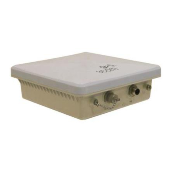
Page 12: Hardware Description
ARDWARE ESCRIPTION Bottom Water Tight Test Point (DO NOT REMOVE) Console Port Cap Attachment Console Port with Grounding Point Ethernet/PoE Protective Cap Connector Integrated Antenna Top View N-Type External Antenna N-Type External Antenna Connector (5 GHz) Connector (2.4 GHz) NTEGRATED NTENNA The WL-575 bridge includes an integrated high-gain (17 dBi) flat-panel antenna for 5 GHz operation. -
Page 13: Ethernet Port
Horizontal Vertical HPBW* HPBW* 2.4 GHz 5.0 GHz (Degrees) (Degrees) 3CWE591 3Com 6/8 dBi Dual-Band Omni 5GHz: 20 2.4GHz: 30 3Com 18/20 dBi Dual-Band Panel 3CWE596 3Com 8/10 dBi Dual-Band Panel 3CWE598 * Half-power beam width External antennas connect to the N-type RF connectors on the wireless bridge using the optional RF coaxial cables. -
Page 14: Grounding Point
network interconnection devices such as a switch or router that provide MDI-X ports. However, when connecting the access point to a workstation or other device that does not have MDI-X ports, you must use crossover twisted-pair cable. AC Power Socket LED Indicator (Hidden) Input... -
Page 15: System Configuration
Ground Wire PERATING ODES The 3Com Outdoor 11a Building to Building Bridge and 11bg Access Point system provides access point or bridging services through either the 5 GHz or 2.4 GHz radio interfaces. The unit supports both point-to-point and point-to-multipoint bridge modes. -
Page 16: Point-To-Point Configuration
The wireless bridge modes connect two or more wired networks, for example networks in different buildings with no wired connections. You will need a 3Com Outdoor 11a Building to Building Bridge and 11bg Access Point unit on both sides of the connection. The wireless bridge can connect up to six remote networks. - Page 17 The following figure shows a point-to-multipoint “in-line” configuration with one bridge set to “Master” and using a directional panel antenna. 19° Beam Angle...
- Page 18 1-10...
-
Page 19: Bridge Link Planning
RIDGE LANNING The 3Com AP Bridge and 11bg Access Point supports fixed point-to-point or point-to-multipoint wireless links. A single link between two points can be used to connect a remote site to larger core network. Multiple bridge links can provide a way to connect widespread Ethernet LANs. -
Page 20: Data Rates
ATES Using the 5.0 GHz integrated antenna, two WL-575 bridges can operate over a range of up to 15.4 km (9.6 miles) or provide a high-speed connection of 54 Mbps (108 Mbps in turbo mode). However, the maximum data rate for a link decreases as the operating range increases. -
Page 21: Radio Path Planning
ADIO LANNING Although the wireless bridge uses IEEE 802.11a radio technology, which is capable of reducing the effect of multipath signals due to obstructions, the wireless bridge link requires a “radio line-of-sight” between the two antennas for optimum performance. The concept of radio line-of-sight involves the area along a radio link path through which the bulk of the radio signal power travels. -
Page 22: Antenna Height
• Be sure there is enough clearance from buildings and that no building construction may eventually block the path. • Check the topology of the land between the antennas using topographical maps, aerial photos, or even satellite image data (software packages are available that may include this information for your area) •... - Page 23 Note that to avoid any obstruction along the path, the height of the object must be added to the minimum clearance required for a clear radio line-of-sight. Consider the following simple example, illustrated in the figure below. Radio Line of Sight Visual Line of Sight 3 miles (4.8 km) 2.4 m...
-
Page 24: Antenna Position And Orientation
NTENNA OSITION AND RIENTATION Once the required antenna height has been determined, other factors affecting the precise position of the wireless bridge must be considered: • Be sure there are no other radio antennas within 2 m (6 ft) of the wireless bridge •... -
Page 25: Radio Interference
ADIO NTERFERENCE The avoidance of radio interference is an important part of wireless link planning. Interference is caused by other radio transmissions using the same or an adjacent channel frequency. You should first scan your proposed site using a spectrum analyzer to determine if there are any strong radio signals using the 802.11a channel frequencies. -
Page 26: Ethernet Cabling
• Snow and Ice — Falling snow, like rain, has no significant effect on the radio signal. However, a build up of snow or ice on antennas may cause the link to fail. In this case, the snow or ice has to be cleared from the antennas to restore operation of the link. -
Page 27: Hardware Installation
ARDWARE NSTALLATION Before mounting antennas to set up your wireless bridge links, be sure you have selected appropriate locations for each antenna. Follow the guidance and information in Chapter 2, “Wireless Link Planning.” Also, before mounting units in their intended locations, you should first perform initial configuration and test the basic operation of the wireless bridge links in a controlled environment over a very short range. -
Page 28: Testing Basic Link Operation
ESTING ASIC PERATION Set up the units over a very short range (15 to 25 feet), either outdoors or indoors. Connect the units as indicated in this chapter and be sure to perform all the basic configuration tasks outlined in Chapter 4, “Initial Configuration.” When you are satisfied that the links are operating correctly, proceed to mount the units in their intended locations. - Page 29 Fit the edges of the V-shaped part into the slots in the rectangular plate, and tighten the nuts. Fit the edges of the V-shaped part into the slots Attach the adjustable rectangular plate to the bridge with supplied screws. Attach the adjustable rectangular plate to the bridge...
-
Page 30: Using The Wall-Mounting Bracket
Attach the bridge with bracket to the plate already fixed to the pole. Attach the bridge to the plate on the pole Use the included nuts to secure the wireless bridge to the pole bracket. Note that the wireless bridge tilt angle may need to be adjusted during the antenna alignment process. - Page 31 Always attach the bracket to a wall with flat side flush against the wall (see following figure). Position the bracket in the intended location and mark the position of the four mounting screw holes. Drill four holes in the wall that match the screws and wall plugs included in the bracket kit, then secure the bracket to the wall.
-
Page 32: Connect External Antennas
ONNECT XTERNAL NTENNAS The bridge’s primary antenna is it’s built-in internal antenna. For some applications when deploying an WL-575 unit for a bridge link or access point operation, you may need to mount external antennas and connect them to the bridge. -
Page 33: Connect Cables To The Unit
ONNECT ABLES TO THE WARNING: Do not connect or disconnect cables or otherwise work with the bridge during periods of lightning activity. Attach the Ethernet cable to the Ethernet port on the wireless bridge. For extra protection against rain or moisture, apply weatherproofing tape (not included) around the Ethernet connector. - Page 34 NOTE: The wireless bridge’s Ethernet port does not support Power over Ethernet (PoE) based on the IEEE 802.3af standard. Do not try to power the unit by connecting it directly to a network switch that provides IEEE 802.3af PoE. Always connect the unit to the included power injector module.
-
Page 35: Check The Led Indicators
LED I HECK THE NDICATORS The bridge’s 11a and 11b/g LEDs operate in two display modes, which are configurable through the software. The default AP mode indicates data traffic rates. The RSSI mode indicates the received signal power and is for use when aligning antennas in a bridge link. -
Page 36: Align Antennas
Color Indicates Amber The 802.11g 2.4 GHz radio is enabled. (Three RSSI Mode: Flashing LEDs) One fully lit LED indicates a low RSSI output level, two LEDs.a medium level, and three LEDs the maximum level. A flashing LED indicates an intermediate RSSI output level AP Mode: One fully lit LED indicates a low... - Page 37 When you move the antenna during alignment, the radio signal from the remote antenna can be seen to have a strong central main lobe and smaller side lobes. The object of the alignment process is to set the antenna so that it is receiving the strongest signal from the central main lobe.
- Page 38 Pan the antenna horizontally back and forth while checking the LEDs. If using the pole-mounting bracket with the unit, you must rotate the mounting bracket around the pole. Other external antenna brackets may require a different horizontal adjustment. Find the point where the signal is strongest (all LEDs on) and secure the horizontal adjustment in that position.
-
Page 39: Initial Configuration
NITIAL ONFIGURATION The 3Com AP Bridge and 11bg Access Point offers a variety of management options, including a web-based interface. The initial configuration steps can be made through the web browser interface. The access point requests an IP address via DHCP by default. If no response is received from the DHCP server, then the access point uses the default address 169.254.2.1. -
Page 40: Using The 3Com Installation Cd
Login name: admin Password: password If the Configuration Management System does not start, the Access Point is on a different subnet than the computer. Install and start the 3Com Wireless Infrastructure Device Manager to discover the Access Point’s IP address. SING THE... - Page 41 Figure 1 Wireless Interface Device Manager Click on the Properties button to see the following screen Figure 2 Wireless Interface Device Manager - Properties Directly connect to the device through its Ethernet port or console port. Follow the instructions below to login into the AP Configuration screen: Load a web browser and enter <http://169.254.2.1>.
-
Page 42: First Time Only
For a new access point installation, the default WLAN Service Area (ESSID) is 3Com and no security is set. Unless it detects a DHCP server on the network, the access point uses Auto IP to assign an IP address of the form 169.254.2.1. - Page 43 Using the Setup Wizard The access point can be managed by any computer using a web browser (such as Internet Explorer 5.0 or above). Enter the default IP address: http://169.254.2.1. NOTE: If you changed the default IP address via the command line interface above, use that address instead of the one shown here.
- Page 44 4: I HAPTER NITIAL ONFIGURATION The home page displays the Main Menu. Figure 5 Home Page Launching the Setup Wizard – To perform initial configuration, click Setup Wizard on the home page, select the VAP you wish to configure, then click on the [Next] button to start the process.
- Page 45 Using the Setup Wizard Figure 7 Setup Wizard - Step 1 Radio Channel – You must enable radio communications for 802.11a and 802.11b/g, and set the operating radio channel. NOTE: Available channel settings are limited by local regulations, which determine the channels that are available.
- Page 46 4: I HAPTER NITIAL ONFIGURATION 802.11a Turbo Mode – If you select Enable, the access point will operate in turbo mode with a data rate of up to 108 Mbps. Turbo mode supports only 5 channels. (Default: Disabled) 802.11a Radio Channel – Set the operating radio channel number.
- Page 47 Using the Setup Wizard NOTE: If there is no DHCP server on your network, then the access point will automatically start up with its default IP address, 169.254.2.1. Security – Set the Authentication Type to “Open” to allow open access without authentication, or “Shared”...
- Page 48 4: I HAPTER NITIAL ONFIGURATION NOTE: All wireless devices must be configured with the same Key ID values to communicate with the access point. Click Finish. Click the OK button to complete the wizard. Figure 11 Setup Wizard - Completed 4-10...
-
Page 49: System Configuration
For a new access point installation, the default WLAN Service Area (ESSID) is 3Com and no security is set. Unless it detects a DHCP server on the network, the access point uses Auto IP to assign an IP address of the form 169.254.2.1. -
Page 50: Advanced Setup
5: S HAPTER YSTEM ONFIGURATION Figure 12 Advanced Setup The information in this chapter is organized to reflect the structure of the web screens for easy reference. However, it is recommended that you configure a user name and password as the first step under Administration to control management access to this device (page 5-30). - Page 51 Advanced Setup Menu Description Page SNMP Configures SNMP settings 5-21 Rogue AP Performs a scan on each VAP to determine any unauthorized APs 5-30 using, or attempting to use the network AP Management Enables Telnet, Web and SNMP on the device 5-31 Administration Configures user name and password for management access;...
-
Page 52: System Identification
5: S HAPTER YSTEM ONFIGURATION YSTEM DENTIFICATION The system name for the access point can be left at its default setting. However, modifying this parameter can help you to more easily distinguish different devices in your network. Figure 13 System Identification System Name –... -
Page 53: Tcp / Ip Settings
IP address that is reachable through your network. By default, the access point will be automatically configured with IP settings from a Dynamic Host Configuration Protocol (DHCP) server. Use 3Com Wireless Infrastructure Device Manager to discover or set the initial IP address of the unit. - Page 54 5: S HAPTER YSTEM ONFIGURATION DHCP Client (Enable) – Select this option to obtain the IP settings for the access point from a DHCP (Dynamic Host Configuration Protocol) server. The IP address, subnet mask, default gateway, and Domain Name Server (DNS) address are dynamically assigned to the access point by the network DHCP server.
- Page 55 TCP / IP Settings Figure 15 Smart Monitor By enabling Smart Monitor (known as Link Integrity in the CLI) and setting a target IP address, the AP will periodically (set by the ping interval) check to see if the target address responds to pings. If it fails to respond to a ping after the configured number of retries, it will disable both radios so that no clients can connect to the AP.
-
Page 56: Radius
5: S HAPTER YSTEM ONFIGURATION RADIUS Remote Authentication Dial-in User Service (RADIUS) is an authentication protocol that uses software running on a central server to control access to RADIUS-aware devices on the network. An authentication server contains a database of user credentials for each user that requires access to the network. - Page 57 RADIUS Figure 16 RADIUS Authentication Primary Radius Server Setup – Configure the following settings to use RADIUS authentication on the access point. IP Address: Specifies the IP address or host name of the RADIUS server. Port: The UDP port number used by the RADIUS server for authentication messages.
- Page 58 5: S HAPTER YSTEM ONFIGURATION NOTE: For the Timeout and Retransmit attempts fields, accept the default values unless you experience problems connecting to the RADIUS server over the network. Secondary Radius Server Setup – Configure a secondary RADIUS server to provide a backup in case the primary server fails.
-
Page 59: Radius Accounting
RADIUS RADIUS A CCOUNTING RADIUS accounting is used to send accounting information to the RADIUS accounting server. Accounting information is sent to the server whenever a subscriber logs in or logs out and whenever a subscriber activates or deactivates a subscription. -
Page 60: Authentication
5: S HAPTER YSTEM ONFIGURATION IP Address: Specifies the IP address or host name of the RADIUS server. Accounting Port: The RADIUS Accounting server UDP port used for accounting messages. (Range: 1024-65535; Default: 1813) Key: A shared text string used to encrypt messages between the access point and the RADIUS server. - Page 61 Authentication certificates, user names and passwords, or other) from the client to the RADIUS server. Client authentication is then verified on the RADIUS server before the access point grants client access to the network. The 802.1X EAP packets are also used to pass dynamic unicast session keys and static broadcast keys to wireless clients.
- Page 62 5: S HAPTER YSTEM ONFIGURATION Figure 18 Authentication MAC Authentication – You can configure a list of the MAC addresses for wireless clients that are authorized to access the network. This provides a basic level of authentication for wireless clients attempting to gain access to the network. A database of authorized MAC addresses can be stored locally on the access point or remotely on a central RADIUS server.
- Page 63 Authentication Local MAC: The MAC address of the associating station is compared against the local database stored on the access point. Use the Local MAC Authentication section of this web page to set up the local database, and configure all access points in the wireless network service area with the same MAC address database.
- Page 64 5: S HAPTER YSTEM ONFIGURATION Session Key Refresh Rate: The interval at which the access point refreshes unicast session keys for associated clients. (Range: 0-1440 minutes; Default: 0 means disabled) 802.1X Reauthentication Refresh Rate: The time period after which a connected client must be re-authenticated.
-
Page 65: Filter Control
Filter Control ILTER ONTROL The access point can employ network traffic frame filtering to control access to network resources and increase security. You can prevent communications between wireless clients and prevent access point management from wireless clients. Also, you can block specific Ethernet traffic from being forwarded by the access point. - Page 66 5: S HAPTER YSTEM ONFIGURATION Using IEEE 802.1X and a central RADIUS server, up to 64 VLAN IDs can be mapped to specific wireless clients, allowing users to remain within the same VLAN as they move around a campus site. This feature can also be used to control access to network resources from clients, thereby improving security.
- Page 67 Filter Control Figure 19 Filter Control Management VLAN ID – The VLAN ID that traffic must have to be able to manage the access point. (Range 1-4094; Default: 1) VLAN Classification – Enables or disables VLAN tagging support on the access point.
- Page 68 5: S HAPTER YSTEM ONFIGURATION Prevent Inter and Intra VAP client communication: When enabled, clients cannot establish wireless communications with any other client, either those associated to the same VAP interface or any other VAP interface. AP Management Filter – Controls management access to the access point from wireless clients.
-
Page 69: Snmp
SNMP Figure 21 Ethernet Type Filter Disabled: Access point does not filter Ethernet protocol types. Enabled: Access point filters Ethernet protocol types based on the configuration of protocol types in the filter table. If the status of a protocol is set to “ON,” the protocol is filtered from the access point. -
Page 70: Configuring Snmp And Trap Message Parameters
5: S HAPTER YSTEM ONFIGURATION The access point includes an onboard agent that supports SNMP versions 1, 2c, and 3 clients. This agent continuously monitors the status of the access point, as well as the traffic passing to and from wireless clients. A network management station can access this information using SNMP management software that is compliant with MIB II. - Page 71 SNMP Figure 22 SNMP SNMP – Globally enables or disables SNMP management access and also enables the access point to send SNMP traps (notifications). (Default: Disable) SNMP v1/v2 – Enables or disables SNMPv1 and SNMPv2 management access and trap notifications. SNMPv3 –...
- Page 72 5: S HAPTER YSTEM ONFIGURATION Trap Destination (1 to 4) – Enables recipients (up to four) of SNMP notifications. Trap Destination IP Address: Specifies the recipient of SNMP notifications. Enter the IP address or the host name. (Host Name: 1 to 63 characters, case sensitive) Trap Destination Community Name: The community string sent with the notification operation.
- Page 73 SNMP Figure 23 Trap Configuration Trap Configuration – Allows selection of specific SNMP notifications to send. The following items are available: sysSystemUp: The access point is up and running. sysSystemDown: The access point is about to shutdown and reboot. sysRadiusServerChanged: The access point has changed from the primary RADIUS server to the secondary, or from the secondary to the primary.
- Page 74 5: S HAPTER YSTEM ONFIGURATION dot11StationAuthentication: A client station has been successfully authenticated. dot11StationRequestFail:A client station has failed association, re-association, or authentication. dot11InterfaceBFail: The 802.11b interface has failed. dot11InterfaceAFail: The 802.11a or 802.11g interface has failed. dot1xMacAddrAuthSuccess: A client station has successfully authenticated its MAC address with the RADIUS server.
-
Page 75: Configuring Snmpv3 Users
SNMP SNMP ONFIGURING SERS The access point allows up to 10 SNMP v3 users to be configured. Each user must be defined by a unique name, assigned to one of three pre-defined security groups, and configured with specific authentication and encryption settings. Figure 24 Configuring SNMPv3 Users User –... -
Page 76: Configuring Snmpv3 Groups
5: S HAPTER YSTEM ONFIGURATION SNMP ONFIGURING ROUPS This feature is display only and details the configured SNMPv3 groups configured. Figure 25 Configuring SNMPv3 Groups SNMP ONFIGURING ARGETS An SNMP v3 notification Target ID is specified by the SNMP v3 user, IP address, and UDP port. -
Page 77: Configuring Snmpv3 Filters
SNMP Assigned Filter: The name of a user-defined notification filter that is applied to the target. SNMP ONFIGURING ILTERS SNMP v3 users can be configured to receive notification messages from the access point. An SNMP Target ID is created that specifies the SNMP v3 user, IP address, and UDP port. -
Page 78: Rogue Ap
5: S HAPTER YSTEM ONFIGURATION OGUE A “rogue AP” is either an access point that is not authorized to participate in the wireless network, or an access point that does not have the correct security configuration. Rogue APs can allow unauthorized access to the network, or fool client stations into mistakenly associating with them and thereby blocking access to network resources. -
Page 79: Ap Management
AP Management Authentication: Enables or disables RADIUS authentication. Enabling RADIUS Authentication allows the access point to discover rogue access points. With RADIUS authentication enabled, the access point checks the MAC address/ Basic Service Set Identifier (BSSID) of each access point that it finds against a RADIUS server to determine whether the access point is allowed. - Page 80 5: S HAPTER YSTEM ONFIGURATION Figure 29 AP Management Management UI – Enables or disables management through Telnet, Wed (HTTP), or SNMP interfaces. Telnet UI Status: Enables or disables management access through Telnet. (Default: Enable) Web UI Status: Enables or disables management access through the web (HTTP) interface.
-
Page 81: Telnet And Ssh Settings
AP Management SSH S ELNET AND ETTINGS Telnet is a remote management tool that can be used to configure the access point from anywhere in the network. However, Telnet is not secure from hostile attacks. The Secure Shell (SSH) can act as a secure replacement for Telnet. The SSH protocol uses generated public keys to encrypt all data transfers passing between the access point and SSH-enabled management station clients and ensures that data traveling over the network arrives unaltered. -
Page 82: Administration
5: S HAPTER YSTEM ONFIGURATION Figure 31 Web Server Settings Web Servers – Enables or disables HTTP and HTTPS settings. HTTP Server: Enables or disables communication to the unit through HTTP. (Default: Enable) HTTP Port: Specifies the HTTP port number used for communication. (Default: 80) HTTPS Server: Enables or disables communication to the unit through HTTPS. -
Page 83: Changing The Country Code
Administration Figure 32 Administration Username – The name of the user. The default name is “admin.” (Length: 3-16 characters, case sensitive) New Password – The password for management access. (Length: 3-16 characters, case sensitive) Confirm New Password – Enter the password again for verification. HANGING THE COUNTRY CODE Upon first booting the unit you are prompted to enter the country code, however should you need to reset the country code the following menu provides the... - Page 84 5: S HAPTER YSTEM ONFIGURATION Figure 34 Firmware Upgrade Before upgrading new software, verify that the access point is connected to the network and has been configured with a compatible IP address and subnet mask. If you need to download from an FTP or TFTP server, take the following additional steps: Obtain the IP address of the FTP or TFTP server where the access point software is stored.
- Page 85 Administration New firmware file: Specifies the name of the code file on the local drive. The new firmware file name should not contain slashes (\ or /), the leading letter of the file name should not be a period (.), and the maximum length for file names is 32 characters for files on the access point.
-
Page 86: Auto-Provisioning
5: S HAPTER YSTEM ONFIGURATION Configuration Data File: Specifies the name of the configuration file. A path on the server can be specified using “/” in the name, providing the path already exists; for example, “myfolder/syscfg.” Other than to indicate a path, the file name must not contain any slashes (\ or /), the leading letter cannot be a period (.), and the maximum length for file names on the TFTP server is 255 characters. - Page 87 Administration Figure 36 Auto-configuration Auto-Config – Schedules automatic updating of configuration data. Config Autoupdate Server: Enables the Bridge/AP to operate as a server that provides its configuration data to other Bride/APs configured as Autoupdate clients. When configured as a server, the username and password used to access its configuration data are username: admin, and password: password (Default: Disable) Config Autoupdate Client: Enables the Bridge/AP to operate as a client that...
- Page 88 5: S HAPTER YSTEM ONFIGURATION NOTE: The Login Username and Password must be the same for all devices designated as servers. Config File Name: Species the configuration file name to look for when performing a search. (Default: syscfg) Save Auto-config/Auto-upgrade Settings: Saves both the auto-config and auto-upgrade settings to system memory.
-
Page 89: Wds And Spanning Tree Settings
PANNING ETTINGS Each 3Com wireless Bridge/AP radio interface can be configured to operate in a WDS mode to link directly to other Bridge/AP units. The Bridge/AP supports three WDS modes; Bridge, Root Bridge, and Repeater. In Bridge and Root Bridge modes, only VAP1 is active, VAPs 2-4 are disabled for the radio interface. - Page 90 5: S HAPTER YSTEM ONFIGURATION router) in your network to ensure that only one route exists between any two stations on the network, and provide backup links which automatically take over when a primary link goes down. Figure 38 WDS and Spanning Tree Settings WDS Setting –...
- Page 91 WDS and Spanning Tree Settings • Bridge: Operates as a bridge to five other access points (slaves), and connects to the “root-bridge” (master). • Repeater: Operates as a wireless repeater, extending the range for remote wireless clients and connecting them to the root-bridge. In this mode, traffic is not forwarded to the Ethernet port from the radio interface.
- Page 92 5: S HAPTER YSTEM ONFIGURATION Figure 39 WDS Scan Copy to location – Specifies the unit to which you want to copy WDS settings. • Bridge Parent: Selects the parent node in the wireless bridge network. • Bridge Child: Selects one of the child nodes in the wireless bridge network. (Range: 2~6) Station to Copy –...
- Page 93 WDS and Spanning Tree Settings Figure 40 Spanning Tree Protocol 5-45...
- Page 94 5: S HAPTER YSTEM ONFIGURATION Figure 41 Spanning Tree Protocol Spanning Tree Protocol – STP uses a distributed algorithm to select a bridging device (STP-compliant switch, bridge or router) that serves as the root of the spanning tree network. It selects a root port on each bridging device (except for the root device) which incurs the lowest path cost when forwarding a packet from that device to the root device.
- Page 95 WDS and Spanning Tree Settings Bridge Priority – Used in selecting the root device, root port, and designated port. The device with the highest priority becomes the STP root device. However, if all devices have the same priority, the device with the lowest MAC address will then become the root device.
- Page 96 5: S HAPTER YSTEM ONFIGURATION • Default: Ethernet interface: 19; Wireless interface: 40 Link Port Priority – Defines the priority used for this port in the Spanning Tree Protocol. If the path cost for all ports on a switch are the same, the port with the highest priority (i.e., lowest value) will be configured as an active link in the spanning tree.
-
Page 97: System Log
System Log YSTEM The access point can be configured to send event and error messages to a System Log Server. The system clock can also be synchronized with a time server, so that all the messages sent to the Syslog server are stamped with the correct time and date. -
Page 98: Configuring Sntp
5: S HAPTER YSTEM ONFIGURATION Primary Server – The IP address the primary Syslog server. (Default: 0.0.0.0) Secondary Server – The IP address the secondary Syslog server. (Default: 0.0.0.0) Enter Time Zone – Sets the desired time zone + or - GMT. Enable Daylight Saving –... - Page 99 System Log Figure 43 SNTP SNTP Server – Configures the access point to operate as an SNTP client. When enabled, at least one time server IP address must be specified. Primary Server: The IP address of an SNTP or NTP time server that the access point attempts to poll for a time update.
-
Page 100: Rssi
5: S HAPTER YSTEM ONFIGURATION RSSI The RSSI value displayed on the RSSI page represents a signal to noise ratio. A value of 30 would indicate that the power of the received signal is 30 dBm above the signal noise threshold. This value can be used to align antennas and monitor the quality of the received signal for bridge links. -
Page 101: Radio Interface
Radio Interface RSSI: Auto Refresh – Enables or disables the refreshing of RSSI information. RSSI Value – The displayed RSSI value for a selected port. Port Number – Selects a specific WDS port for which to display the RSSI output value. - Page 102 NOTE: The Building to Building Bridge/AP ships from the factory enabled only for channels allowed in the US/Canada. If you live in an area where additional channels are allowed, go to the 3Com web site (http://www.3com.com) and download the latest software that will allow additional channels in your country.
-
Page 103: Interface
Radio Interface 802.11 NTERFACE The IEEE 802.11a interface operates within the 5 GHz band, at up to 54 Mbps in normal mode or up to 108 Mbps in Turbo mode. First configure the radio settings that apply to the individual VAPs (Virtual Access Point) and the common radio settings that apply to the overall system. - Page 104 5: S HAPTER YSTEM ONFIGURATION VLAN ID – The VLAN ID assigned to wireless clients associated to the VAP interface that are not assigned to a specific VLAN by RADIUS server configuration. (Default: 1) Hide SSID – When enabled, the VAP interface does not include its SSID in beacon messages.
- Page 105 Radio Interface ONFIGURING OMMON ADIO ETTINGS To configure common radio settings, select the Radio Settings page, and scroll down to below the VAP radio settings. Figure 46 Radio Settings A and B/G Country Code – The current country code setting. This setting restricts operation of the access point to radio channels and transmit power levels permitted for wireless networks in the specified country.
- Page 106 Selecting the correct antenna ID ensures that the access point's radio transmissions are within regulatory power limits for the country of operation. (Default: 3Com Integrated Antenna) NOTE: The 802.11b/g Antenna ID must be selected to enable the radio, and to configure any of the Output Antenna options.
- Page 107 Output Antenna – Specifies the ID number of an approved antenna that is connected to the access point. The options are: 802.11a (5 GHz): Original 3Com Integrated Antenna 3CWE591 3Com 6/8dBi Dual-Band Omni Antenna 3CWE596 3Com 18/20dBi Dual-Band Panel Antenna 3CWE598 3Com 8/10dBi Dual-Band Panel Antenna 802.11b/g (2.4 GHz):...
- Page 108 5: S HAPTER YSTEM ONFIGURATION The DTIM interval indicates how often the MAC layer forwards broadcast/multicast traffic, which is necessary to wake up stations that are using Power Save mode. The default value of 1 indicates that the access point will save all broadcast/multicast frames for the Basic Service Set (BSS) and forward them after every beacon.
-
Page 109: Configuring Common Radio Settings
Radio Interface First configure the radio settings that apply to the individual VAPs (Virtual Access Point) and the common radio settings that apply to all of the 802.11g interfaces. After you have configured the radio settings, enable the radio service for any of the VAP interfaces, and then set an SSID to identify the wireless network service provided by each VAP. - Page 110 5: S HAPTER YSTEM ONFIGURATION Figure 47 Radio Settings B/G Client Access Mode – Selects the operating mode for the 802.11g wireless interface. (Default: 802.11b+g) 802.11b+g: Both 802.11b and 802.11g clients can communicate with the access point (up to 54 Mbps). 802.11b only: Both 802.11b and 802.11g clients can communicate with the access point, but 802.11g clients can only transfer data at 802.11b standard rates (up to 11 Mbps).
- Page 111 Radio Interface NOTE: In normal mode, the access point supports the maximum number of channels permitted by local regulations (e.g., 11 channels for the United States). In Turbo mode, channel bonding is used to provide the increased data rate. However, this reduces the number of channels available to one (Channel 6).
- Page 112 5: S HAPTER YSTEM ONFIGURATION ONFIGURING ULTIMEDIA Wireless networks offer an equal opportunity for all devices to transmit data from any type of application. Although this is acceptable for most applications, multimedia applications (with audio and video) are particularly sensitive to the delay and throughput variations that result from this equal opportunity wireless access method.
- Page 113 Radio Interface WMM Access Categories Access 802.1D Description Category Designation Tags Normal priority, medium delay and throughput. Data only affected by long AC_BE (AC0) Best Effort 0, 3 delays. Data from applications or devices that lack QoS capabilities. Lowest priority. Data with no delay or AC_BK (AC1) Background throughput requirements, such as bulk...
- Page 114 5: S HAPTER YSTEM ONFIGURATION Figure 48 WMM Backoff Times Time CWMin CWMax High Priority AIFS Random Backoff Minimum Wait Time Random Wait Time CWMin CWMax Low Priority AIFS Random Backoff Minimum Wait Time Random Wait Time For high-priority traffic, the AIFSN and CW values are smaller. The smaller values equate to less backoff and wait time, and therefore more transmit opportunities.
- Page 115 Radio Interface Support: WMM will be used for any associated device that supports this feature. Devices that do not support this feature may still associate with the access point. Required: WMM must be supported on any device trying to associated with the access point.
-
Page 116: Security
5: S HAPTER YSTEM ONFIGURATION ECURITY The access point is configured by default as an “open system,” which broadcasts a beacon signal including the configured SSID. Wireless clients with an SSID setting of “any” can read the SSID from the beacon and automatically set their SSID to allow immediate connection to the nearest access point. - Page 117 Security Security Client Support Implementation Considerations Mechanism WPA over 802.1X Requires WPA-enabled system • Provides robust security in WPA-only mode Mode and network card driver (i.e., WPA clients only) (native support provided in • Offers support for legacy WEP clients, but with Windows XP) increased security risk (i.e., WEP authentication keys disabled)
- Page 118 5: S HAPTER YSTEM ONFIGURATION Client Security RADIUS Configuration Summary Combination Authentication Server Dynamic WEP Authentication: Open System Local, RADIUS, or (802.1x) only Encryption: Enable Disabled 802.1x: Required Set 802.1x key refresh and re authentication rates 802.1x WPA only Authentication: WPA Local only Encryption: Enable WPA Configuration: Required...
-
Page 119: Wired Equivalent Privacy (Wep)
Security Client Security RADIUS Configuration Summary Combination Authentication Server 802.1x WPA-WPA2 Authentication: WPA-WPA2-mixed Local or Disabled Mixed Mode Encryption: Enable WPA Configuration: Required Cipher Suite: TKIP 802.1x: Required Set 802.1x key refresh and re authentication rates WPA-WPA2 Mixed Authentication: WPA-WPA2-PSK-mixed Local or Disabled Mode Pre-Shared Key Encryption: Enable... - Page 120 5: S HAPTER YSTEM ONFIGURATION Note that all clients share the same keys, which are used for user authentication and data encryption. Up to four keys can be specified. These four keys are used for all VAP interfaces on the same radio. To set up WEP shared keys, click Radio Settings under 802.11a or 802.11b/g, then select Authentication ‘Shared’.
- Page 121 Security NOTE: To use 802.1X on wireless clients requires a network card driver and 802.1X client software that supports the EAP authentication type that you want to use. Windows 2000 SP3 or later and Windows XP provide 802.1X client support. Windows XP also provides native WPA support.
- Page 122 5: S HAPTER YSTEM ONFIGURATION Key – Selects the key number to use for encryption for each VAP interface. If the clients have all four keys configured to the same values, you can change the encryption key to any of the four settings without having to update the client keys.
-
Page 123: Wi-Fi Protected Access (Wpa)
Security • Alphanumeric: Enter keys as 5 alphanumeric characters for 64 bit keys, 13 alphanumeric characters for 128 bit keys, or 16 alphanumeric characters for 152 bit keys (802.11a radio only). Key – Selects the key number to use for encryption for each VAP interface. If the clients have all four keys configured to the same values, you can change the encryption key to any of the four settings without having to update the client keys. - Page 124 5: S HAPTER YSTEM ONFIGURATION Temporal Key Integrity Protocol (TKIP): WPA specifies TKIP as the data encryption method to replace WEP. TKIP avoids the problems of WEP static keys by dynamically changing data encryption keys. Basically, TKIP starts with a master (temporal) key for each user session and then mathematically generates other keys to encrypt each data packet.
- Page 125 Security for WPA2. However, the computational intensive operations of AES-CCMP requires hardware support on client devices. Therefore to implement WPA2 in the network, wireless clients must be upgraded to WPA2-compliant hardware. WPA2 Mixed-Mode: WPA2 defines a transitional mode of operation for networks moving from WPA security to WPA2.
-
Page 126: Status Information
5: S HAPTER YSTEM ONFIGURATION Status Information The Status page includes information on the following items: Access Point Status The AP Status window displays basic system configuration settings, as well as the settings for the wireless interface. Figure 53 AP Status AP System Configuration –... - Page 127 Security System Contact: Administrator responsible for the system. IP Address: IP address of the management interface for this device. IP Default Gateway: IP address of the gateway router between this device and management stations that exist on other network segments. HTTP Server: Shows if management access via HTTP is enabled.
- Page 128 5: S HAPTER YSTEM ONFIGURATION Figure 54 Station Status The Station Configuration page displays basic connection information for all associated stations as described below. Note that this page is automatically refreshed every five seconds. Station Address: The MAC address of the wireless client. Authenticated: Shows if the station has been authenticated.
- Page 129 Security Rogue AP Status The Neighbor AP Detection Status window shows the RSSI values of neighboring APs detected by the unit during it’s last scan. NOTE: Rogue AP Status scans are background activities that will not prevent you from working with the unit, however throughput may be lowered. Figure 55 Rogue AP Status The Neighbor AP Detection Status table displays the following information: SSID –...
- Page 130 5: S HAPTER YSTEM ONFIGURATION RSSI The RSSI Monitor window performs a realtime scan that shows the RSSI values of neighboring APs detected by the unit. The scan is performed when the RSSI Monitor tab is selected in the Status menu. NOTE: Initiating an RSSI scan will impact network connectivity for the duration of the scan and will halt your access to the management interface until it completes.
- Page 131 Security BSSID – The MAC address that identifies the detected device. Event Logs The Event Logs window shows the log messages generated by the access point and stored in memory. Figure 57 Event Logs The Event Logs table displays the following information: Clear Logs: Clears the currently stored log list.
- Page 132 5: S HAPTER YSTEM ONFIGURATION 5-84...
-
Page 133: Accessing The Cli
OMMAND NTERFACE SING THE OMMAND NTERFACE CCESSING THE When accessing the management interface either over a direct connection to the console port, or via a Telnet connection, the access point can be managed by entering command keywords and parameters at the prompt. Using the access point’s command-line interface (CLI) is very similar to entering commands on a UNIX system. -
Page 134: Telnet Connection
6: C HAPTER OMMAND NTERFACE Telnet Connection Telnet operates over the IP transport protocol. In this environment, your management station and any network device you want to manage over the network must have a valid IP address. Valid IP addresses consist of four numbers, 0 to 255, separated by periods. -
Page 135: Entering Commands
Using the Command Line Interface NTERING OMMANDS This section describes how to enter CLI commands. Keywords and Arguments A CLI command is a series of keywords and arguments. Keywords identify a command, and arguments specify configuration parameters. For example, in the command “show interface ethernet,”... -
Page 136: Showing Commands
6: C HAPTER OMMAND NTERFACE Showing Commands If you enter a “?” at the command prompt, the system will display the first level of keywords for the current configuration mode (Exec, Global Configuration, or Interface). You can also display a list of valid keywords for a specific command. For example, the command “show ?”... -
Page 137: Negating The Effect Of Commands
Using the Command Line Interface Negating the Effect of Commands For many configuration commands you can enter the prefix keyword “no” to cancel the effect of a command or reset the configuration to the default value. For example, the logging command will log system messages to a host server. To disable logging, specify the no logging command. -
Page 138: Configuration Commands
6: C HAPTER OMMAND NTERFACE Configuration Commands Configuration commands are used to modify access point settings. These commands modify the running configuration and are saved in memory. The configuration commands are organized into four different modes: • Global Configuration (GC) - These commands modify the system level configuration, and include commands such as username and password. -
Page 139: Command Groups
Using the Command Line Interface Keystroke Function Ctrl-C Terminates a task and displays the command prompt. Ctrl-E Shifts cursor to end of command line. Ctrl-F Shifts cursor to the right one character. Ctrl-K Deletes from cursor to the end of the command line. Ctrl-L Repeats current command line on a new line. - Page 140 6: C HAPTER OMMAND NTERFACE Command Group Description Page Wireless Interface Configures radio interface settings 6-137 Wireless Security Configures radio interface security and encryption settings 6-159 Rogue AP Detection Configures settings for the detection of rogue access points in the 6-159 network Link Integrity...
- Page 141 Using the Command Line Interface Command Mode Exec Example AP #configure AP (config)# Related Commands end (6-9) This command returns to the previous configuration mode. Default Setting None Command Mode Global Configuration, Interface Configuration Example This example shows how to return to the Configuration mode from the Interface Configuration mode: AP (if-ethernet)#end AP (config)#...
- Page 142 6: C HAPTER OMMAND NTERFACE ping This command sends ICMP echo request packets to another node on the network. Syntax ping <host_name | ip_address> • host_name - Alias of the host. • ip_address - IP address of the host. Default Setting None Command Mode Exec...
- Page 143 Using the Command Line Interface reset This command restarts the system or restores the factory default settings. Syntax reset <board | configuration> • board - Reboots the system. • configuration - Resets the configuration settings to the factory defaults, and then reboots the system. Default Setting None Command Mode...
-
Page 144: System Management Commands
6: C HAPTER OMMAND NTERFACE Example In this example, the show history command lists the contents of the command history buffer: AP #show history exit show history AP # show line This command displays the console port’s configuration settings. Command Mode Exec Example The console port settings are fixed at the values shown below. - Page 145 Using the Command Line Interface Command Function Mode Page username Configures the user name for management access 6-16 password Specifies the password for management access 6-17 ip ssh-server enable Enables the Secure Shell server IC-E 6-17 ip ssh-server port Sets the Secure Shell port IC-E 6-18 ip telnet-server enable Enables the Telnet server...
- Page 146 6: C HAPTER OMMAND NTERFACE Command Function Mode Page System Status show system Displays system information Exec 6-35 show version Displays version information for the system Exec 6-36 show config Displays detailed configuration information for the system Exec 6-36 show hardware Displays the access point’s hardware version Exec 6-62...
- Page 147 Using the Command Line Interface Country Code Country Code Country Code Country Code Bulgaria Indonesia Qatar United Arab Emirates Canada Iran Oman OM United Kingdom Chile Ireland Pakistan United States China Israel Panama Uruguay Colombia Italy Peru Uzbekistan Costa Rica Japan Philippines Yemen...
- Page 148 6: C HAPTER OMMAND NTERFACE Default Setting Command Mode Global Configuration Example AP (config)#prompt RD2 RD2(config)# system name This command specifies or modifies the system name for this device. Syntax system name <name> name - The name of this host. (Maximum length: 32 characters) Default Setting Enterprise Outdoor Wireless Bridge/AP...
- Page 149 Using the Command Line Interface Command Mode Global Configuration Example AP (config)#username bob AP (config)# password After initially logging onto the system, you should set the password. Remember to record it in a safe place. Use the no form to reset the default password. Syntax password <password>...
- Page 150 6: C HAPTER OMMAND NTERFACE Command Usage • The access point supports Secure Shell version 2.0 only. • After boot up, the SSH server needs about two minutes to generate host encryption keys. The SSH server is disabled while the keys are being generated.
- Page 151 Using the Command Line Interface Command Mode Interface Configuration (Ethernet) Example AP(if-ethernet)#ip telnet-server enable AP(if-ethernet)# ip http port This command specifies the TCP port number used by the web browser interface. Use the no form to use the default port. Syntax ip http port <port-number>...
- Page 152 6: C HAPTER OMMAND NTERFACE Command Mode Global Configuration Example AP (config)#ip http server AP (config)# Related Commands ip http port (6-19) ip https port Use this command to specify the UDP port number used for HTTPS/SSL connection to the access point’s Web interface. Use the no form to restore the default port.
- Page 153 Using the Command Line Interface ip https server Use this command to enable the secure hypertext transfer protocol (HTTPS) over the Secure Socket Layer (SSL), providing secure access (i.e., an encrypted connection) to the access point’s Web interface. Use the no form to disable this function.
- Page 154 6: C HAPTER OMMAND NTERFACE Command Mode Global Configuration Command Usage • The web redirect feature is used to support billing for a public access wireless network. After successful association to an access point, a client is “redirected” to an access point login web page as soon as Internet access is attempted.
- Page 155 Using the Command Line Interface Command Mode Global Configuration Command Usage • If anyone tries to access a management interface on the access point from an invalid address, the unit will reject the connection, enter an event message in the system log, and send a trap message to the trap manager. •...
- Page 156 6: C HAPTER OMMAND NTERFACE Default Setting All enabled Command Mode Global Configuration Example This example restricts management access to the indicated addresses. AP (config)#apmgmtui SNMP enable AP (config)# autoconfig server-status This command enables the unit to operate as a server that provides updated configuration files to units operating as clients.
- Page 157 Using the Command Line Interface autoconfig client-status This command enables the unit to operate as a client that sends requests to a specified server for configuration file updates, and schedules the times at which the requests are sent. Syntax autoconfig client-status <disable | imediately | startup | startup+periodic>...
- Page 158 6: C HAPTER OMMAND NTERFACE Default Setting 24 hours Command Mode Global Configuration Example This example schedules periodic updates every week (168 hours). AP (config)#autoconfig interval 168 AP (config)# autoconfig filename This command specifies the filename to look for when performing a search for a configuration file update.
- Page 159 Using the Command Line Interface autoconfig IP This command specifies the servers on which to search for configuration file updates. Syntax autoconfig IP <[ 1 | 2 | 3 | 4] IP_address> • 1~4 - The server on which to search for updates, up to a maximum of 4. - IP_address - Specifies the IP address of the auto-configuration server in the form xx.xx.xx.xx.
- Page 160 6: C HAPTER OMMAND NTERFACE Command Mode Global Configuration Example This example specifies a username “3Com1” to use for communication between the client and the server. AP (config)#autoconfig username 3Com1 AP (config)# autoconfig password This command specifies a password for authentication between client and server. NOTE: The autoconfig password must be the same for all devices designated as servers.
- Page 161 Using the Command Line Interface show autoconfig This command displays the auto-configuration settings. Syntax show autoconfig Default Setting Disable Command Mode Global Configuration Example This example displays all auto-configuration settings. AP (config)#show auto-config Config Autoupdate Information =========================================================== Server Status : Enable Client Status : Startup and Periodic Polling Interval...
- Page 162 6: C HAPTER OMMAND NTERFACE • startup+periodic - Schedules a search each time the unit boots up and periodically. The periodic parameter may be configured using the autoconfig interval command. Default Setting Disabled Command Mode Global Configuration Example This example schedules a search for configuration file updates at each boot up and periodically.
- Page 163 Using the Command Line Interface autoupgrade directory This command specifies the directory in which to search for firmware updates on the local PC designated to be an auto-upgrade server. NOTE: Firmware files used with this feature must be in the following format; A73_xx_yy_zz_sh.img (shipping version), or A73_xx_yy_zz_ww.img (world wide version).
- Page 164 6: C HAPTER OMMAND NTERFACE Default Setting 0.0.0.0 Command Mode Global Configuration Example This example specifies the IP addresses for a server. AP (config)#autoupgrade IP 2 192.168.1.1 AP (config)# autoupgrade password This command specifies the password used to gain access to the server/s for firmware upgrades.
- Page 165 Using the Command Line Interface autoupgrade username This command specifies the username used to gain access to the server/s for firmware upgrades. NOTE: The autoupgrade username must be the same for all devices designated as servers. Syntax autoconfig username string string - The username used to gain access to the server/s specified as having configuration file updates.
-
Page 166: Show Apmanagement
6: C HAPTER OMMAND NTERFACE Example This example displays all auto-upgrade settings. AP (config)#show autoupgrade Firmware Autoupgrade Information =========================================================== Client Status : Enabled Polling Interval : 24 hours Server 1 IP : 169.254.10.0 Server 2 IP : 169.254.20.0 Server 3 IP : 0.0.0.0 Server 4 IP : 0.0.0.0... - Page 167 Using the Command Line Interface show system This command displays basic system configuration settings. Default Setting None Command Mode Exec Example AP #show system System Information ========================================================== Serial Number : A123456789 System Up time : 0 days, 4 hours, 33 minutes, 29 seconds System Name : Enterprise Outdoor Wireless Bridge/AP System Location...
-
Page 168: Show Version
6: C HAPTER OMMAND NTERFACE show version This command displays the software version for the system. Command Mode Exec Example AP #show version Version Information ========================================= Software Version : v2.2.14tmp4_sh Date : Nov 16 2007, 19:45:24 BootRom Version : v1.2.3 Hardware Version : R01 =========================================... - Page 169 : ALLOWED System Default : ALLOW addresses not found in filter table. Filter Table ----------------------------------------------------------- No Filter Entries. =========================================================== Bootfile Information =================================== Bootfile : 3com-img.bin =================================== Bridge Setting Information =========================================================== Aging time: Bridge MAC Address Table Information =========================================================== max entry numbers...
- Page 170 6: C HAPTER OMMAND NTERFACE Bridge Port/Link Information (Ethernet) =========================================================== Port-No status : Enabled state : Forwarding priority : 128 path cost : 19 message age Timer : Inactive message age designated-root : priority = 0, MAC = 00:00:00:00:00:00 designated-cost designated-bridge : priority = 0, MAC = 00:00:00:00:00:00 designated-port...
- Page 171 Using the Command Line Interface forward-transitions : 0 Bridge Port/Link Information (Wireless A 3) =========================================================== Port-No : 12 status : Enabled state : Forwarding priority : 128 path cost : 19 message age Timer : Inactive message age designated-root : priority = 0, MAC = 00:00:00:00:00:00 designated-cost designated-bridge : priority = 0, MAC = 00:00:00:00:00:00...
- Page 172 6: C HAPTER OMMAND NTERFACE Bridge Port/Link Information (Wireless A 6) =========================================================== Port-No : 15 status : Enabled state : Forwarding priority : 128 path cost : 19 message age Timer : Inactive message age designated-root : priority = 0, MAC = 00:00:00:00:00:00 designated-cost designated-bridge : priority = 0, MAC = 00:00:00:00:00:00...
- Page 173 Using the Command Line Interface Bridge Port/Link Information (Wireless G 3) =========================================================== Port-No : 18 status : Enabled state : Forwarding priority : 128 path cost : 19 message age Timer : Inactive message age designated-root : priority = 0, MAC = 00:00:00:00:00:00 designated-cost designated-bridge : priority = 0, MAC = 00:00:00:00:00:00...
- Page 174 6: C HAPTER OMMAND NTERFACE Bridge Port/Link Information (Wireless G 6) =========================================================== Port-No : 21 status : Enabled state : Forwarding priority : 128 path cost : 19 message age Timer : Inactive message age designated-root : priority = 0, MAC = 00:00:00:00:00:00 designated-cost designated-bridge : priority = 0, MAC = 00:00:00:00:00:00...
- Page 175 Using the Command Line Interface ID EdgeCore_VAP_G 0, Channel 13 (2472 MHz), RSSI 6, Type ESS, Privacy 0, RSN 0 Jan 02 00:01:32 Alert: 802.11g: Invalid AP detected: BSSID 00-13-f7-0a-2e-aa, SS ID 802_11g_wep, Channel 6 (2437 MHz), RSSI 1, Type ESS, Privacy 0, RSN 0 Jan 02 00:01:32 Alert: 802.11g: Invalid AP detected: BSSID 00-13-f7-8b-59-a5, SS ID Juan_Test_1, Channel 6 (2437 MHz), RSSI 5, Type ESS, Privacy 1, RSN 0 Jan 02 00:01:32 Alert: 802.11g: Invalid AP detected: BSSID 00-13-f7-19-22-97, SS...
- Page 176 6: C HAPTER OMMAND NTERFACE Jan 01 19:30:20 Information: 802.11g:Description updated to Enterprise 802.11g Access Point Jan 01 19:30:20 Information: 802.11g:Description updated to Enterprise 802.11g Access Point Jan 01 19:30:20 Information: 802.11g:Can't enable virtual AP when physical AP is disabled Jan 01 19:30:20 Information: 802.11g:Can't enable virtual AP when physical AP is disabled Jan 01 19:30:20 Information: 802.11g:Can't enable virtual AP when physical AP is...
- Page 177 Using the Command Line Interface Traffic Filter Information ======================================================================= Local Bridge :Traffic among client STAs within same VAP blocked AP Management :ENABLED Ethernet Type Filter :DISABLED UPlink Access Table ----------------------------------------------------------------------- UPlink access control:Disabled UPlink MAC access control list : There is no any mac address. ----------------------------------------------------------------------- Enabled Protocol Filters -----------------------------------------------------------------------...
- Page 178 Key 2: EMPTY Key 3: EMPTY Key 4: EMPTY Pre-Authentication : DISABLED Authentication Type : OPEN ----------------Antenna-------------------------------------------------- Antenna ID : 3CWE591 3Com 6/8dBi Dual-Band Omni Antenna (External) ----------------Quality of Service--------------------------------------- WMM Mode : DISABLED WMM Acknowledge Policy AC0(Best Effort) : Acknowledge AC1(Background)
- Page 179 Maximum Association : 64 stations MIC Mode : Software Super A : Disabled VLAN ID ----------------Antenna-------------------------------------------------- Antenna ID : 3CWE591 3Com 6/8dBi Dual-Band Omni Antenna (External) ----------------Quality of Service--------------------------------------- WMM Mode : DISABLED WMM Acknowledge Policy AC0(Best Effort) : Acknowledge AC1(Background)
- Page 180 6: C HAPTER OMMAND NTERFACE WMM AP Parameters AC0(Best Effort) : logCwMin: logCwMax: AIFSN: Admission Control: No TXOP Limit: 0.000 ms AC1(Background) : logCwMin: logCwMax: 10 AIFSN: Admission Control: No TXOP Limit: 0.000 ms AC2(Video) : logCwMin: logCwMax: AIFSN: Admission Control: No TXOP Limit: 3.008 ms AC3(Voice) : logCwMin:...
- Page 181 Using the Command Line Interface Pre-Authentication : DISABLED Authentication Type : OPEN ----------------Antenna-------------------------------------------------- Antenna ID : 3CWE591 3Com 6/8dBi Dual-Band Omni Antenna (External) ----------------Quality of Service--------------------------------------- WMM Mode : DISABLED WMM Acknowledge Policy AC0(Best Effort) : Acknowledge AC1(Background) : Acknowledge...
- Page 182 Key 2: EMPTY Key 3: EMPTY Key 4: EMPTY Pre-Authentication : DISABLED Authentication Type : OPEN ----------------Antenna-------------------------------------------------- Antenna ID : 3CWE591 3Com 6/8dBi Dual-Band Omni Antenna (External) ----------------Quality of Service--------------------------------------- WMM Mode : DISABLED WMM Acknowledge Policy AC0(Best Effort) : Acknowledge AC1(Background)
- Page 183 Using the Command Line Interface WMM AP Parameters AC0(Best Effort) : logCwMin: logCwMax: AIFSN: Admission Control: No TXOP Limit: 0.000 ms AC1(Background) : logCwMin: logCwMax: 10 AIFSN: Admission Control: No TXOP Limit: 0.000 ms AC2(Video) : logCwMin: logCwMax: AIFSN: Admission Control: No TXOP Limit: 3.008 ms AC3(Voice) : logCwMin:...
- Page 184 Key 4: EMPTY Pre-Authentication : DISABLED Authentication Type : OPEN ----------------Antenna-------------------------------------------------- Antenna Control method : Diversity Antenna ID : 3CWE591 3Com 6/8dBi Dual-Band Omni Antenna ----------------Quality of Service--------------------------------------- WMM Mode : DISABLED WMM Acknowledge Policy AC0(Best Effort) : Acknowledge AC1(Background)
- Page 185 Key 4: EMPTY Pre-Authentication : DISABLED Authentication Type : OPEN ----------------Antenna-------------------------------------------------- Antenna Control method : Diversity Antenna ID : 3CWE591 3Com 6/8dBi Dual-Band Omni Antenna ----------------Quality of Service--------------------------------------- WMM Mode : DISABLED WMM Acknowledge Policy AC0(Best Effort) : Acknowledge AC1(Background)
- Page 186 6: C HAPTER OMMAND NTERFACE TXOP Limit: 3.008 ms AC3(Voice) : logCwMin: logCwMax: AIFSN: Admission Control: No TXOP Limit: 1.504 ms WMM AP Parameters AC0(Best Effort) : logCwMin: logCwMax: AIFSN: Admission Control: No TXOP Limit: 0.000 ms AC1(Background) : logCwMin: logCwMax: 10 AIFSN: Admission Control: No...
- Page 187 Key 4: EMPTY Pre-Authentication : DISABLED Authentication Type : OPEN ----------------Antenna-------------------------------------------------- Antenna Control method : Diversity Antenna ID : 3CWE591 3Com 6/8dBi Dual-Band Omni Antenna ----------------Quality of Service--------------------------------------- WMM Mode : DISABLED WMM Acknowledge Policy AC0(Best Effort) : Acknowledge AC1(Background)
- Page 188 6: C HAPTER OMMAND NTERFACE AC0(Best Effort) : logCwMin: logCwMax: 10 AIFSN: Admission Control: No TXOP Limit: 0.000 ms AC1(Background) : logCwMin: logCwMax: 10 AIFSN: Admission Control: No TXOP Limit: 0.000 ms AC2(Video) : logCwMin: logCwMax: AIFSN: Admission Control: No TXOP Limit: 3.008 ms AC3(Voice) : logCwMin:...
- Page 189 Using the Command Line Interface ====================================================== PPPoE Information ====================================================== State : Disabled Username Service Name IP Allocation Mode : Dynamic DNS Negotiation : Disabled Remote IP : 0.0.0.0 Echo Interval : 10 Echo Failure ====================================================== Radius Server Information ======================================== Status : Disabled : 0.0.0.0 Port...
- Page 190 6: C HAPTER OMMAND NTERFACE Timeout InterimUpdate : 3600 Radius Accounting Secondary Server Information ======================================== Accounting Log Options : RADIUS Authenticated Client Only Accounting Server State : DOWN ======================================== Rogue AP Information =========================================================== 802.11a Channel : Rogue AP Setting =========================================================================== Rogue AP Detection : Enabled Rogue AP Authentication...
- Page 191 Using the Command Line Interface EngineId :80:00:07:e5:80:00:00:27:04:00:00:00:12 EngineBoots:5 Trap Destinations: 0.0.0.0, Community: *****, State: Disabled 0.0.0.0, Community: *****, State: Disabled 0.0.0.0, Community: *****, State: Disabled 0.0.0.0, Community: *****, State: Disabled dot11Disassociate Enabled dot11Deauthenticate Enabled dot11AuthenticateFail Enabled sysSystemUp Enabled sysSystemDown Enabled radiusServerChanged Enabled configFileVersionChanged...
- Page 192 6: C HAPTER OMMAND NTERFACE SNTP Information =========================================================== Service State : Disabled SNTP (server 1) IP : 0.0.0.0 SNTP (server 2) IP : 0.0.0.0 Current Time : 02 : 49, Jan 2nd, 1970 Time Zone : -5 (BOGOTA, EASTERN, INDIANA) Daylight Saving : Disabled ===========================================================...
- Page 193 Using the Command Line Interface ============================================================== System Information ============================================================== Serial Number : 9TCC7CJ094F3A System Up time : 1 days, 2 hours, 51 minutes, 42 seconds System Name : Enterprise Outdoor Wireless Bridge/AP System Location System Contact : Contact System Country Code : US - UNITED STATES MAC Address : 00-18-6E-09-4F-3A...
-
Page 194: Show Hardware
6: C HAPTER OMMAND NTERFACE show hardware This command displays the hardware version of the system. Command Mode Exec Example AP #show hardware Hardware Version Information =========================================== Hardware version R01 =========================================== AP # System Logging Commands These commands are used to configure system logging on the access point. Table 13 System Loggign Commands Command Function... - Page 195 Using the Command Line Interface Command Usage The logging process controls error messages saved to memory. You can use the logging level command to control the type of error messages that are stored in memory. Example AP (config)#logging on AP (config)# logging host This command specifies syslog servers host that will receive logging messages.
- Page 196 6: C HAPTER OMMAND NTERFACE logging console This command initiates logging of error messages to the console. Use the no form to disable logging to the console. Syntax [no] logging console Default Setting Disabled Command Mode Global Configuration Example AP (config)#logging console AP (config)# logging level This command sets the minimum severity level for event logging.
- Page 197 Using the Command Line Interface Command Usage Messages sent include the selected level down to Emergency level. Level Argument Description Emergency System unusable Alert Immediate action needed Critical Critical conditions (e.g., memory allocation, or free memory error - resource exhausted) Error Error conditions (e.g., invalid input, default used) Warning...
- Page 198 6: C HAPTER OMMAND NTERFACE Example AP (config)#logging facility 19 AP (config)# logging clear This command clears all log messages stored in the access point’s memory. Syntax logging clear Command Mode Global Configuration Example AP (config)#logging clear AP (config)# show logging This command displays the logging configuration.
-
Page 199: System Clock Commands
Using the Command Line Interface show event-log This command displays log messages stored in the access point’s memory. Syntax show event-log Command Mode Exec Example AP#show event-log Mar 09 11:57:55 Information: 802.11g:11g Radio Interface Enabled Mar 09 11:57:55 Information: 802.11g:Radio channel updated to 8 Mar 09 11:57:34 Information: 802.11g:11g Radio Interface Enabled Mar 09 11:57:18... - Page 200 6: C HAPTER OMMAND NTERFACE sntp-server ip This command sets the IP address of the servers to which SNTP time requests are issued. Use the this command with no arguments to clear all time servers from the current list. Syntax sntp-server ip <1 | 2>...
- Page 201 Using the Command Line Interface Default Setting Enabled Command Mode Global Configuration Command Usage The time acquired from time servers is used to record accurate dates and times for log events. Without SNTP, the access point only records the time starting from the factory default set at the last bootup (i.e., 00:14:00, January 1, 1970).
- Page 202 6: C HAPTER OMMAND NTERFACE sntp-server daylight-saving This command sets the start and end dates for daylight savings time. Use the no form to disable daylight savings time. Syntax [no] sntp-server daylight-saving Default Setting Disabled Command Mode Global Configuration Command Usage The command sets the system clock back one hour during the specified period.
- Page 203 Using the Command Line Interface Command Usage This command sets the local time zone relative to the Coordinated Universal Time (UTC, formerly Greenwich Mean Time or GMT), based on the earth’s prime meridian, zero degrees longitude. To display a time corresponding to your local time, you must indicate the number of hours and minutes your time zone is east (before) or west (after) of UTC.
-
Page 204: Dhcp Relay Commands
6: C HAPTER OMMAND NTERFACE DHCP Relay Commands Dynamic Host Configuration Protocol (DHCP) can dynamically allocate an IP address and other configuration information to network clients that broadcast a request. To receive the broadcast request, the DHCP server would normally have to be on the same subnet as the client. - Page 205 Using the Command Line Interface dhcp-relay This command configures the primary and secondary DHCP server addresses. Syntax dhcp-relay <primary | secondary> <ip_address> • primary - The primary DHCP server. • secondary - The secondary DHCP server. • ip_address - IP address of the server. Default Setting Primary and secondary: 0.0.0.0 Command Mode...
-
Page 206: Snmp Commands
6: C HAPTER OMMAND NTERFACE SNMP Commands Controls access to this access point from management stations using the Simple Network Management Protocol (SNMP), as well as the hosts that will receive trap messages. Table 16 SNMP Commands Command Function Mode Page snmp-server community Sets up the community access string to permit access... - Page 207 Using the Command Line Interface snmp-server community This command defines the community access string for the Simple Network Management Protocol. Use the no form to remove the specified community string. Syntax snmp-server community string [ro | rw] no snmp-server community string •...
- Page 208 6: C HAPTER OMMAND NTERFACE Default Setting None Command Mode Global Configuration Example AP (config)#snmp-server contact Paul AP (config)# Related Commands snmp-server location (6-76) snmp-server location This command sets the system location string. Use the no form to remove the location string.
- Page 209 Using the Command Line Interface snmp-server enable server This command enables SNMP management access and also enables this device to send SNMP traps (i.e., notifications). Use the no form to disable SNMP service and trap messages. Syntax snmp-server enable server no snmp-server enable server Default Setting Enabled...
- Page 210 6: C HAPTER OMMAND NTERFACE • host_name - Name of the host. (Range: 1-63 characters) • community-string - Password-like community string sent with the notification operation. Although you can set this string using the snmp-server host command by itself, we recommend that you define this string using the snmp-server community command prior to using the snmp-server host command.
- Page 211 Using the Command Line Interface - dot11StationRequestFail - A client station has failed association, re-association, or authentication. - dot1xAuthFail - A 802.1X client station has failed RADIUS authentication. - dot1xAuthNotInitiated - A client station did not initiate 802.1X authentication. - dot1xAuthSuccess - A 802.1X client station has been successfully authenticated by the RADIUS server.
- Page 212 6: C HAPTER OMMAND NTERFACE Command Usage This command is used in conjunction with the snmp-server host and snmp-server enable server commands to enable SNMP notifications. Example AP(config)#no snmp-server trap dot11StationAssociation AP(config)# snmp-server engine-id This command is used for SNMP v3. It is used to uniquely identify the access point among all access points in the network.
- Page 213 Using the Command Line Interface snmp-server user This command configures the SNMP v3 users that are allowed to manage the access point. Use the no form to delete an SNMP v3 user. Syntax snmp-server user <user-name> user-name - A user-defined string for the SNMP user. (32 characters maximum) Default Setting None...
- Page 214 6: C HAPTER OMMAND NTERFACE - group-name - The name of the SNMP group to which the user is assigned (32 characters maximum). There are three pre-defined groups: RO, RWAuth, or RWPriv. - auth-proto - The authentication type used for user authentication: md5 or none.
- Page 215 Using the Command Line Interface • ip-addr - Specifies the IP address of the management station to receive notifications. • sec-name - The defined SNMP v3 user name that is to receive notifications. • version - The SNMP version of notifications. Currently only version 3 is supported in this command.
- Page 216 6: C HAPTER OMMAND NTERFACE Default Setting None Command Mode Global Configuration Command Usage • The access point allows up to 10 notification filters to be created. Each filter can be defined by up to 20 MIB subtree ID entries. •...
- Page 217 Using the Command Line Interface Command Mode Global Configuration Example AP(config)#snmp-server filter-assignments mytraps trapfilter AP(config)#exit AP#show snmp target Host ID : mytraps User : chris IP Address : 192.254.2.33 UDP Port : 162 ============================= AP#show snmp filter-assignments HostID FilterID mytraps trapfilter AP(config)# show snmp groups...
- Page 218 6: C HAPTER OMMAND NTERFACE show snmp users This command displays the SNMP v3 users and settings. Syntax show snmp users Command Mode Exec Example AP#show snmp users ============================================= UserName :chris GroupName :RWPriv AuthType :MD5 Passphrase:**************** PrivType :DES Passphrase:**************** ============================================= show snmp group-assignments This command displays the SNMP v3 user group assignments.
- Page 219 Using the Command Line Interface show snmp target This command displays the SNMP v3 notification target settings. Syntax show snmp target Command Mode Exec Example AP#show snmp target Host ID : mytraps User : chris IP Address : 192.254.2.33 UDP Port : 162 ============================= show snmp filter...
- Page 220 6: C HAPTER OMMAND NTERFACE show snmp filter-assignments This command displays the SNMP v3 notification filter assignments. Syntax show snmp filter-assignments Command Mode Exec Example AP#show snmp filter-assignments HostID FilterID mytraps trapfilter 6-88...
- Page 221 Using the Command Line Interface show snmp This command displays the SNMP configuration settings. Command Mode Exec Example AP #show snmp SNMP Information ============================================== Service State : Enable Community (ro) : ***** Community (rw) : ***** Location : WC-19 Contact : Paul EngineId :80:00:07:e5:80:00:00:2e:62:00:00:00:18...
- Page 222 6: C HAPTER OMMAND NTERFACE Flash/File Commands These commands are used to manage the system code or configuration files. Table 17 Flash/File Commands Command Function Mode Page bootfile Specifies the file or image used to start up the system 6-90 copy Copies a code image or configuration between flash Exec...
- Page 223 Using the Command Line Interface copy This command copies a boot file, code image, or configuration file between the access point’s flash memory and a FTP/TFTP server. When you save the configuration settings to a file on a FTP/TFTP server, that file can later be downloaded to the access point to restore system operation.
- Page 224 6: C HAPTER OMMAND NTERFACE The following example shows how to download a configuration file: AP #copy tftp file 1. Application image 2. Config file 3. Boot block image Select the type of download<1,2,3>: [1]:2 TFTP Source file name:syscfg TFTP Server IP:192.254.2.19 AP # delete This command deletes a file or image.
- Page 225 Using the Command Line Interface This command displays a list of files in flash memory. Command Mode Exec Command Usage File information is shown below: Column Heading Description File Name The name of the file. Type (2) Operation Code and (5) Configuration file File Size The length of the file in bytes.
-
Page 226: Radius Client
6: C HAPTER OMMAND NTERFACE Example AP#show bootfile Bootfile Information =================================== Bootfile : ec-img.bin =================================== RADIUS Client Remote Authentication Dial-in User Service (RADIUS) is a logon authentication protocol that uses software running on a central server to control access for RADIUS-aware devices to the network. - Page 227 Using the Command Line Interface Default Setting None Command Mode Global Configuration Example AP (config)#radius-server address 192.254.2.25 AP (config)# radius-server port This command sets the RADIUS server network port. Syntax radius-server [secondary] port <port_number> • secondary - Secondary server. • port_number - RADIUS server UDP port used for authentication messages. (Range: 1024-65535) Default Setting 1812...
- Page 228 6: C HAPTER OMMAND NTERFACE Command Mode Global Configuration Example AP (config)#radius-server key green AP (config)# radius-server retransmit This command sets the number of retries. Syntax radius-server [secondary] retransmit number_of_retries • secondary - Secondary server. • number_of_retries - Number of times the access point will try to authenticate logon access via the RADIUS server.
- Page 229 Using the Command Line Interface Example AP (config)#radius-server timeout 10 AP (config)# radius-server radius-mac-format This command sets the format for specifying MAC addresses on the RADIUS server. Syntax radius-server radius-mac-format <multi-colon | multi-dash | no-delimiter | single-dash> • multi-colon - Enter MAC addresses in the form xx:xx:xx:xx:xx:xx. •...
-
Page 230: Show Radius
6: C HAPTER OMMAND NTERFACE Command Mode Global Configuration Example AP(config)#radius-server vlan-format ascii AP (config)# show radius This command displays the current settings for the RADIUS server. Default Setting None Command Mode Exec Example AP #show radius Radius Server Information ======================================== Status : Disabled... - Page 231 Using the Command Line Interface Radius Accounting Server Information ======================================== Status : Disabled : 169.254.10.1 Accounting Port : 1813 : ***** Retransmit Timeout InterimUpdate : 3600 Accounting Log Options : RADIUS Authenticated Client Only Accounting Server State : DOWN ======================================== Radius Accounting Secondary Server Information ======================================== Status...
- Page 232 6: C HAPTER OMMAND NTERFACE Command Function Mode Page radius-accounting timeout Sets the interval in between sending RADIUS 6-103 Accounting authentication requests radius-accounting Sets the interval between transmitting accounting 6-104 timeout-interim updates to the RADIUS Accounting server show radius Shows the current RADIUS settings Exec 6-98 radius-accounting enable...
- Page 233 Using the Command Line Interface Default Setting none Command Mode Global Configuration Command Usage • When the RADIUS Accounting server address is specified user data may be logged to that address. • When a secondary RADIUS Accounting server address is specified user data is logged to the primary server but will transfer to the secondary server if there is a fault with the primary server.
- Page 234 6: C HAPTER OMMAND NTERFACE radius-accounting log This command specifies the type of clients the RADIUS Accounting server may collect data on. Syntax radius-accounting log [all-client | radius-client-only] • all-client - Sends accounting data for all clients, both RADIUS authenticated and non-RADIUS authenticated. •...
- Page 235 Using the Command Line Interface radius-accounting retransmit This command sets the number of retries. Syntax radius-accounting [secondary] retransmit number_of_retries • secondary - Secondary server. • number_of_retries - Number of times the access point will try to authenticate logon access via the RADIUS server. (Range: 1 - 30) Default Setting Command Mode Global Configuration...
- Page 236 6: C HAPTER OMMAND NTERFACE radius-accounting timeout-interim This command sets the interval between transmitting accounting updates to the RADIUS Accounting server. Syntax radius-accounting timeout-interim <number_of_seconds> • number_of_seconds - Number of seconds the access point waits between transmitting accounting updates. (Range: 60-86400) Default Setting 3600 Command Mode...
- Page 237 Using the Command Line Interface Command Function Mode Page 802.1x session-timeout Sets the timeout after which a connected client must be IC-W-VAP 6-107 re-authenticated 802.1x-supplicant enable Enables the access point to operate as a 802.1X 6-108 supplicant 802.1x-supplicant user Sets the supplicant user name and password for the 6-108 access point show authentication...
- Page 238 6: C HAPTER OMMAND NTERFACE • When 802.1X is required, the access point enforces 802.1X authentication for all 802.11 associated stations. If 802.1X authentication is not initiated by the station, the access point will initiate authentication. Only those stations successfully authenticated with 802.1X are allowed to access the network.
- Page 239 Using the Command Line Interface 802.1x session-key-refresh-rate This command sets the interval at which unicast session keys are refreshed for associated stations using dynamic keying. Syntax 802.1x session-key-refresh-rate <rate> rate - The interval at which the access point refreshes a session key. (Range: 0 - 1440 minutes) Default Setting 0 (Disabled)
- Page 240 6: C HAPTER OMMAND NTERFACE Example AP (config)#802.1x session-timeout 300 AP (config)# 802.1x-supplicant enable This command enables the access point to operate as an 802.1X supplicant for authentication. Use the no form to disable 802.1X authentication of the access point. Syntax 802.1x-supplicant enable no 802.1x-supplicant...
-
Page 241: Show Authentication
Using the Command Line Interface Command Mode Global Configuration Command Usage The access point currently only supports EAP-MD5 CHAP for 802.1X supplicant authentication. Example AP(config)#802.1x-supplicant user AP8760 dot1xpass AP(config)# show authentication This command shows all 802.1X authentication settings, as well as the address filter table. -
Page 242: Mac Address Authentication
6: C HAPTER OMMAND NTERFACE MAC Address Authentication Use these commands to define MAC authentication on the access point. For local MAC authentication, first define the default filtering policy using the address filter default command. Then enter the MAC addresses to be filtered, indicating if they are allowed or denied. - Page 243 Using the Command Line Interface Example AP (config)#address filter default denied AP (config)# Related Commands address filter entry (6-111) 802.1x-supplicant user (6-108) address filter entry This command enters a MAC address in the filter table. Syntax address filter entry <mac-address> <allowed | denied> •...
- Page 244 6: C HAPTER OMMAND NTERFACE address filter delete This command deletes a MAC address from the filter table. Syntax address filter delete <mac-address> mac-address - Physical address of client. (Enter six pairs of hexadecimal digits separated by hyphens.) Default None Command Mode Global Configuration Example...
-
Page 245: Filtering Commands
Using the Command Line Interface Related Commands address filter entry (6-111) radius-server address (6-94) 802.1x-supplicant user (6-108) mac-authentication session-timeout This command sets the interval at which associated clients will be re-authenticated with the RADIUS server authentication database. Use the no form to disable reauthentication. - Page 246 6: C HAPTER OMMAND NTERFACE Command Function Mode Page filter ethernet-type Sets a filter for a specific Ethernet type 6-117 protocol show filters Shows the filter configuration Exec 6-117 filter local-bridge This command disables communication between wireless clients. Use the no form to disable this filtering.
- Page 247 Using the Command Line Interface filter ap-manage This command prevents wireless clients from accessing the management interface on the access point. Use the no form to disable this filtering. Syntax [no] filter ap-manage Default Enabled Command Mode Global Configuration Example AP (config)#filter AP-manage AP (config)# filter uplink enable...
- Page 248 6: C HAPTER OMMAND NTERFACE Default Disabled Command Mode Global Configuration Example AP (config)#filter uplink add 00-12-34-56-78-9a AP (config)# filter ethernet-type enable This command checks the Ethernet type on all incoming and outgoing Ethernet packets against the protocol filtering table. Use the no form to disable this feature.
- Page 249 Using the Command Line Interface filter ethernet-type protocol This command sets a filter for a specific Ethernet type. Use the no form to disable filtering for a specific Ethernet type. Syntax filter ethernet-type protocol <protocol> no filter ethernet-type protocol <protocol> protocol - An Ethernet protocol type.
-
Page 250: Wds Bridge Commands
6: C HAPTER OMMAND NTERFACE Example AP #show filters Protocol Filter Information ======================================================================= Local Bridge :Traffic among all client STAs blocked AP Management :ENABLED Ethernet Type Filter :DISABLED UPlink Access Table ----------------------------------------------------------------------- UPlink access control:Enabled UPlink MAC access control list 00-12-34-56-78-9a ----------------------------------------------------------------------- Enabled Protocol Filters... - Page 251 Using the Command Line Interface bridge mode This command selects between Master and Slave mode. Syntax bridge mode <master | slave> • master - Operates as a master enabling up to five slave links. • slave - Operates as a slave with only one link to the master. Default Setting Master Command Mode...
- Page 252 6: C HAPTER OMMAND NTERFACE When the access point is operating in this mode, traffic is not forwarded to the Ethernet port from the radio interface. • Up to six WDS bridge links (MAC addresses) per radio interface can be specified for each unit in the wireless bridge network.
- Page 253 Using the Command Line Interface bridge-link parent This command configures the MAC address of the parent bridge node. Syntax bridge-link parent <mac-address> mac-address - The wireless MAC address of the parent bridge unit. (12 hexadecimal digits in the form “xx-xx-xx-xx-xx-xx”). Default Setting None Command Mode...
- Page 254 6: C HAPTER OMMAND NTERFACE • In bridge mode, up to five child links can be specified using link index numbers 2 to 6. Index number 1 is reserved for the parent link, which must be set using the bridge parent command. Example AP(if-wireless a)#bridge-link child 2 00-08-3e-84-bc-6d AP(if-wireless a)#bridge-link child 3 00-08-3e-85-13-f2...
- Page 255 Using the Command Line Interface show bridge filter-entry This command displays current entries in the WDS forwarding table. Command Mode Exec Example AP#show bridge filter-entry max entry numbers =512 current entry nums =13 **************************************************************** *********************** Bridge MAC Addr Table *********** **************************************************************** Port |Fwd_type| VlanID|origin life|remain Life|...
- Page 256 6: C HAPTER OMMAND NTERFACE show bridge link This command displays WDS bridge link and spanning tree settings for specified interfaces. Syntax show bridge link <ethernet | wireless <a | g> [index]> • ethernet - Specifies the Ethernet interface. • wireless - Specifies a wireless interface. - a - The 802.11a radio interface.
-
Page 257: Spanning Tree Commands
Using the Command Line Interface AP#show bridge link wireless a 2 Port-No : 11 status : Enabled state : Disabled priority path cost : 19 message age Timer : Inactive message age : 4469 designated-root : priority = 32768, MAC = 00:30:F1:F0:9A:9C designated-cost designated-bridge : priority = 32768, MAC = 00:30:F1:F0:9A:9C... - Page 258 6: C HAPTER OMMAND NTERFACE Command Function Mode Page show bridge stp Displays the global spanning tree settings Exec 6-130 show bridge link Displays current bridge settings for specified interfaces Exec 6-124 bridge stp enable This command enables the Spanning Tree Protocol. Use the no form to disable the Spanning Tree Protocol.
- Page 259 Using the Command Line Interface Command Usage This command sets the maximum time (in seconds) the root device will wait before changing states (i.e., discarding to learning to forwarding). This delay is required because every device must receive information about topology changes before it starts to forward frames.
- Page 260 6: C HAPTER OMMAND NTERFACE bridge stp max-age Use this command to configure the spanning tree bridge maximum age globally for the wireless bridge. Use the no form to restore the default. Syntax bridge stp max-age <seconds> no bridge stp max-age seconds - Time in seconds.
- Page 261 Using the Command Line Interface Default Setting 32768 Command Mode Global Configuration Command Usage Bridge priority is used in selecting the root device, root port, and designated port. The device with the highest priority becomes the STP root device. However, if all devices have the same priority, the device with the lowest MAC address will then become the root device.
- Page 262 6: C HAPTER OMMAND NTERFACE bridge-link port-priority Use this command to configure the priority for the specified port. Syntax bridge-link port-priority <index> <priority> • index - Specifies the bridge link number on the wireless bridge. (Range: 1-6 required on wireless interface only) •...
-
Page 263: Ethernet Interface Commands
Using the Command Line Interface Example AP#show bridge stp Bridge MAC : 00:12:CF:05:B7:84 Status : Disabled priority designated-root : priority = 0, MAC = 00:00:00:00:00:00 root-path-cost root-Port-no Hold Time 1 Seconds Hello Time 2 Seconds Maximum Age 20 Seconds Forward Delay 15 Seconds bridge Hello Time 2 Seconds... - Page 264 6: C HAPTER OMMAND NTERFACE interface ethernet This command enters Ethernet interface configuration mode. Default Setting None Command Mode Global Configuration Example To specify the 10/100Base-TX network interface, enter the following command: AP (config)#interface ethernet AP (if-ethernet)# dns server This command specifies the address for the primary or secondary domain name server to be used for name-to-address resolution.
- Page 265 Using the Command Line Interface Related Commands show interface ethernet (6-136) ip address This command sets the IP address for the access point. Use the no form to restore the default IP address. Syntax ip address <ip-address> <netmask> <gateway> no ip address •...
- Page 266 6: C HAPTER OMMAND NTERFACE ip dhcp This command enables the access point to obtain an IP address from a DHCP server. Use the no form to restore the default IP address. Syntax [no] ip dhcp Default Setting Enabled Command Mode Interface Configuration (Ethernet) Command Usage •...
- Page 267 Using the Command Line Interface speed-duplex This command configures the speed and duplex mode of a given interface when autonegotiation is disabled. Use the no form to restore the default. Syntax speed-duplex <auto | 10MH | 10MF | 100MF | 100MH> •...
- Page 268 6: C HAPTER OMMAND NTERFACE Command Usage This command allows you to disable the Ethernet port due to abnormal behavior (e.g., excessive collisions), and reenable it after the problem has been resolved. You may also want to disable the Ethernet port for security reasons.
-
Page 269: Wireless Interface Commands
Using the Command Line Interface Wireless Interface Commands The commands described in this section configure connection parameters for the wireless interfaces. Table 26 Wireless Interface Commands Command Function Mode Page interface wireless Enters wireless interface configuration mode 6-138 Provides access to the VAP interface configuration IC-W 6-139 mode... -
Page 270: Interface Wireless
6: C HAPTER OMMAND NTERFACE Command Function Mode Page ssid Configures the service set identifier IC-W-VAP 6-151 closed system Opens access to clients without a pre-configured IC-W-VAP 6-152 SSID max-association Configures the maximum number of clients that can IC-W-VAP 6-152 be associated with the access point at the same time assoc- timeout-interval Configures the idle time interval (when no frames are... - Page 271 Using the Command Line Interface This command provides access to the VAP (Virtual Access Point) interface configuration mode. Syntax vap <vap-id> vap-id - The number that identifies the VAP interface. (Options: 0-3) Default Setting None Command Mode Interface Configuration (Wireless) Example AP (if-wireless g)#vap 0 AP (if-wireless g: VAP[0])#...
- Page 272 6: C HAPTER OMMAND NTERFACE (e.g., setting the speed to 54 Mbps limits the effective maximum speed to 108 Mbps). Example AP (if-wireless g)#speed 6 AP (if-wireless g)# turbo This command sets the access point to an enhanced proprietary modulation mode (not regulated in IEEE 802.11a) that provides a higher data rate of up to 108 Mbps.
- Page 273 Using the Command Line Interface multicast-data-rate This command configures the maximum data rate at which the access point transmits multicast and management packets (excluding beacon packets) on the wireless interface. Syntax multicast-data-rate <speed> speed - Maximum transmit speed allowed for multicast data. (Options for 802.11a: 6, 12, 24 Mbps) (Options for 802.11b/g;...
- Page 274 6: C HAPTER OMMAND NTERFACE Command Usage • The available channel settings are limited by local regulations, which determine the number of channels that are available. • When multiple access points are deployed in the same area, be sure to choose a channel separated by at least two channels for 802.11a to avoid having the channels interfere with each other, and at least five channels for 802.11b/g.
- Page 275 Using the Command Line Interface Example AP (if-wireless g)#transmit-power half AP (if-wireless g)# radio-mode This command forces the operating mode for the 802.11g wireless interface. Syntax radio-mode <b | g | b+g> • b - b-only mode: Both 802.11b and 802.11g clients can communicate with the access point, but 802.11g clients can only transfer data at 802.11b standard rates (up to 11 Mbps).
- Page 276 6: C HAPTER OMMAND NTERFACE preamble This command sets the length of the signal preamble that is used at the start of a 802.11b/g data transmission. Syntax preamble [long | short-or-long] • long - Sets the preamble to long (192 microseconds). •...
- Page 277 • antenna-id - Specifies the ID number of an approved antenna that is connected to the access point. The options are: 802.11a: Original 3Com Integrated Antenna 3CWE591 3Com 6/8dBi Dual-Band Omni Antenna 3CWE596 3Com 18/20dBi Dual-Band Panel Antenna 3CWE598 3Com 8/10dBi Dual-Band Panel Antenna 802.11b/g:...
- Page 278 6: C HAPTER OMMAND NTERFACE Command Usage • The optional external antennas (if any) that are certified for use with the access point are listed by typing antenna control id ?. Selecting the correct antenna ID ensures that the access point's radio transmissions are within regulatory power limits for the country of operation.
- Page 279 Using the Command Line Interface beacon-interval This command configures the rate at which beacon signals are transmitted from the access point. Syntax beacon-interval <interval> interval - The rate for transmitting beacon signals. (Range: 20-1000 milliseconds) Default Setting Command Mode Interface Configuration (Wireless) Command Usage The beacon signals allow wireless clients to maintain contact with the access point.
- Page 280 6: C HAPTER OMMAND NTERFACE Command Usage • The Delivery Traffic Indication Map (DTIM) packet interval value indicates how often the MAC layer forwards broadcast/multicast traffic. This parameter is necessary to wake up stations that are using Power Save mode. •...
- Page 281 Using the Command Line Interface fragment size to send smaller fragments. This will speed up the retransmission of smaller frames. However, it is more efficient to set the fragment size larger if very little or no interference is present because it requires overhead to send multiple frames.
- Page 282 6: C HAPTER OMMAND NTERFACE super-a This command enables Atheros proprietary Super A performance enhancements. Use the no form to disable this function. Syntax [no] super-a Default Setting Disabled Command Mode Interface Configuration (Wireless - 802.11a) Command Usage Super A enhancements include bursting, compression, and fast frames. Maximum throughput ranges between 40 to 60 Mbps for connections to Atheros-compatible clients.
- Page 283 Using the Command Line Interface Command Usage These enhancements include bursting, compression, fast frames and dynamic turbo. Maximum throughput ranges between 40 to 60 Mbps for connections to Atheros-compatible clients. Example AP (if-wireless a)#super g AP (if-wireless a)# description This command adds a description to a the wireless interface. Use the no form to remove the description.
- Page 284 6: C HAPTER OMMAND NTERFACE Command Mode Interface Configuration (Wireless-VAP) Command Usage Clients that want to connect to the wireless network via an access point must set their SSIDs to the same as that of the access point. Example AP (if-wireless g: VAP[0])#ssid RD-AP#3 AP (if-wireless g)# closed-system This command prohibits access to clients without a pre-configured SSID.
- Page 285 Using the Command Line Interface Default Setting Command Mode Interface Configuration (Wireless-VAP) Example AP (if-wireless g: VAP[0])#max-association 32 AP (if-wireless g)# assoc-timeout-interval This command configures the idle time interval (when no frames are sent) after which the client is disassociated from the VAP interface. Syntax assoc-timeout-interval <minutes>...
- Page 286 6: C HAPTER OMMAND NTERFACE Command Mode Interface Configuration (Wireless-VAP) Example AP (if-wireless g: VAP[0])#auth-timeout-value 40 AP (if-wireless g: VAP[0])# shutdown This command disables the wireless interface. Use the no form to restart the interface. Syntax [no] shutdown Default Setting Interface enabled Command Mode Interface Configuration (Wireless-VAP)
- Page 287 Using the Command Line Interface Command Mode Exec Example AP #show interface wireless g 0 Wireless Interface Information ========================================================================= ----------------Identification------------------------------------------- Description : Enterprise 802.11g Access Point SSID : VAP_G 0 Channel : 1 (AUTO) Status : ENABLED MAC Address : 00:03:7f:fe:03:02 ----------------802.11 Parameters---------------------------------------- Radio Mode : b &...
- Page 288 6: C HAPTER OMMAND NTERFACE ----------------Security------------------------------------------------- Closed System : Disabled Multicast cipher : WEP Unicast cipher : TKIP and AES WPA clients : DISABLED WPA Key Mgmt Mode : PRE SHARED KEY WPA PSK Key Type : PASSPHRASE WPA PSK Key : EMPTY PMKSA Lifetime : 720 minutes...
- Page 289 Using the Command Line Interface WMM AP Parameters AC0(Best Effort) : logCwMin: logCwMax: AIFSN: Admission Control: No TXOP Limit: 0.000 ms AC1(Background) : logCwMin: logCwMax: 10 AIFSN: Admission Control: No TXOP Limit: 0.000 ms AC2(Video) : logCwMin: logCwMax: AIFSN: Admission Control: No TXOP Limit: 3.008 ms AC3(Voice) : logCwMin:...
-
Page 290: Show Station
6: C HAPTER OMMAND NTERFACE show station This command shows the wireless clients associated with the access point. Command Mode Exec Example AP #show station Station Table Information ======================================================== if-wireless A VAP [0] 802.11a Channel : 60 No 802.11a Channel Stations. if-wireless G VAP [0] 802.11g Channel : 1 802.11g Channel Station Table... -
Page 291: Rogue-Ap Enable
Using the Command Line Interface Rogue AP Detection Commands A “rogue AP” is either an access point that is not authorized to participate in the wireless network, or an access point that does not have the correct security configuration. Rogue APs can potentially allow unauthorized users access to the network. -
Page 292: Rogue-Ap Authenticate
6: C HAPTER OMMAND NTERFACE scanning or scans of a long duration unless there is a reason to believe that more intensive scanning is required to find a rogue AP. • A “rogue AP” is either an access point that is not authorized to participate in the wireless network, or an access point that does not have the correct security configuration. -
Page 293: Rogue-Ap Duration
Using the Command Line Interface the access points are allowed or are rogues. If you enable authentication, you should also configure a RADIUS server for this access point (see “RADIUS” on page 8). Example AP (if-wireless g)#rogue-ap authenticate AP (if-wireless g)# rogue-ap duration This command sets the scan duration for detecting access points. -
Page 294: Rogue-Ap Interval
6: C HAPTER OMMAND NTERFACE rogue-ap interval This command sets the interval at which to scan for access points. Syntax rogue-ap interval <minutes> minutes - The interval between consecutive scans. (Range: 30-10080 minutes) Default Setting 720 minutes Command Mode Interface Configuration (Wireless) Command Usage This command sets the interval at which scans occur. -
Page 295: Wireless Security Commands
Using the Command Line Interface Example AP (if-wireless g)#rogue-ap scan AP (if-wireless g)#rogueApDetect Completed (Radio G) : 9 APs detected rogueAPDetect (Radio G): refreshing ap database now AP (if-wireless g)# show rogue-ap This command displays the current rogue AP database. Command Mode Exec Example... - Page 296 6: C HAPTER OMMAND NTERFACE Command Function Mode Page cipher-suite Selects an encryption method for the global key used IC-W-VAP 6-169 for multicast and broadcast traffic mic_mode Specifies how to calculate the Message Integrity IC-W 6-170 Check (MIC) wpa-pre-shared- key Defines a WPA preshared-key value IC-W-VAP 6-171...
- Page 297 Using the Command Line Interface Command Usage • The auth command automatically configures settings for each authentication type, including encryption, 802.1X, and cipher suite. The command auth open-system disables encryption and 802.1X. • To use WEP shared-key authentication, set the authentication type to “shared-key”...
- Page 298 6: C HAPTER OMMAND NTERFACE • The “required” option places the VAP into TKIP only mode. The “supported” option places the VAP into TKIP+AES+WEP mode. The “required” mode is used in WPA-only environments. • The “supported” mode can be used for mixed environments with legacy WPA products, specifically WEP.
- Page 299 Using the Command Line Interface Example AP (if-wireless g: VAP[0])#encryption AP (if-wireless g)# Related Commands key (6-167) This command sets the keys used for WEP encryption. Use the no form to delete a configured key. Syntax key <index> <size> <type> <value> no key index •...
- Page 300 6: C HAPTER OMMAND NTERFACE Example AP (if-wireless g)#key 1 64 hex 1234512345 AP (if-wireless g)#key 2 128 ascii asdeipadjsipd AP (if-wireless g)#key 3 64 hex 12345123451234512345123456 AP (if-wireless g)# Related Commands key (6-167) encryption (6-166) transmit-key (6-168) transmit-key This command sets the index of the key to be used for encrypting data frames for broadcast or multicast traffic transmitted from the VAP to wireless clients.
- Page 301 Using the Command Line Interface • In a mixed-mode environment with clients using static and dynamic keys, select transmit key index 2, 3, or 4. The access point uses transmit key index 1 for the generation of dynamic keys. Example AP (if-wireless g: VAP[0])#transmit-key 2 AP (if-wireless g)# cipher-suite...
- Page 302 6: C HAPTER OMMAND NTERFACE and a re-keying mechanism. Select TKIP if there are clients in the network that are not WPA2 compliant. • TKIP defends against attacks on WEP in which the unencrypted initialization vector in encrypted packets is used to calculate the WEP key. TKIP changes the encryption key on each packet, and rotates not just the unicast keys, but the broadcast keys as well.
- Page 303 Using the Command Line Interface Command Usage • The Michael Integrity Check (MIC) is part of the Temporal Key Integrity Protocol (TKIP) encryption used in Wi-Fi Protected Access (WPA) security. The MIC calculation is performed in the access point for each transmitted packet and this can impact throughput and performance.
- Page 304 6: C HAPTER OMMAND NTERFACE Example AP (if-wireless g: VAP[0])#wpa-pre-shared-key ASCII agoodsecret AP (if-wireless g)# Related Commands auth (6-164) pmksa-lifetime This command sets the time for aging out cached WPA2 Pairwise Master Key Security Association (PMKSA) information for fast roaming. Syntax pmksa-lifetime <minutes>...
- Page 305 Using the Command Line Interface pre-authentication This command enables WPA2 pre-authentication for fast secure roaming. Syntax pre-authentication <enable | disable> • enable - Enables pre-authentication for the VAP interface. • disable - Disables pre-authentication for the VAP interface. Default Setting Disabled Command Mode Interface Configuration (Wireless-VAP)
-
Page 306: Link Integrity Commands
6: C HAPTER OMMAND NTERFACE Link Integrity Commands The access point provides a link integrity feature that can be used to ensure that wireless clients are connected to resources on the wired network. The access point does this by periodically sending Ping messages to a host device in the wired Ethernet network. - Page 307 Using the Command Line Interface host does not respond or is unreachable) exceeds the limit set by the link-integrity ping-fail-retry command, the link is determined as lost. Example AP (config)#link-integrity ping-detect AP (config)# link-integrity ping-host This command configures the link host name or IP address. Use the no form to remove the host setting.
- Page 308 6: C HAPTER OMMAND NTERFACE Example AP (config)#link-integrity ping-interval 20 AP (config)# link-integrity ping-fail-retry This command configures the number of consecutive failed Ping counts before the link is determined as lost. Syntax link-integrity ping-fail-retry <counts> counts - The number of failed Ping counts before the link is determined as lost.
-
Page 309: Iapp Commands
Using the Command Line Interface show link-integrity This command displays the current link integrity configuration. Command Mode Exec Example AP #show link-integrity Link Integrity Information =========================================================== Ethernet Detect : Enabled Ping Detect : Enabled Target IP/Name : 192.254.0.140 Ping Fail Retry : 6 Ping Interval : 30 ===========================================================... -
Page 310: Vlan Commands
6: C HAPTER OMMAND NTERFACE between access points from different vendors. This command is used to enable or disable 802.11f handover signaling between different access points, especially in a multi-vendor environment. Example AP (config)#iapp AP (config)# VLAN Commands The access point can enable the support of VLAN-tagged traffic passing between wireless clients and the wired network. - Page 311 Using the Command Line Interface vlan This command enables VLANs for all traffic. Use the no form to disable VLANs. Syntax [no] vlan enable Default Disabled Command Mode Global Configuration Command Description • When VLANs are enabled, the access point tags frames received from wireless clients with the VLAN ID configured for each client on the RADIUS server.
- Page 312 6: C HAPTER OMMAND NTERFACE Command Usage The management VLAN is for managing the access point. For example, the access point allows traffic that is tagged with the specified VLAN to manage the access point via remote management, SSH, SNMP, Telnet, etc. Example AP (config)#management-vlanid 3 AP (config)#...
-
Page 313: Wmm Commands
Using the Command Line Interface WMM Commands The access point implements QoS using the Wi-Fi Multimedia (WMM) standard. Using WMM, the access point is able to prioritize traffic and optimize performance when multiple applications compete for wireless network bandwidth at the same time. WMM employs techniques that are a subset of the developing IEEE 802.11e QoS standard and it enables the access point to inter-operate with both WMM- enabled clients and other devices that may lack any WMM functionality. - Page 314 6: C HAPTER OMMAND NTERFACE Example AP(if-wireless a)#wmm required AP(if-wireless a)# wmm-acknowledge-policy This command allows the acknowledgement wait time to be enabled or disabled for each Access Category (AC). Syntax wmm-acknowledge-policy <ac_number> <ack | noack> • ac_number - Access categories. (Range: 0-3) •...
- Page 315 Using the Command Line Interface wmmparam This command configures detailed WMM parameters that apply to the access point (AP) or the wireless clients (BSS). Syntax wmmparam <AP | BSS> <ac_number> <LogCwMin> <LogCwMax> <AIFS> <TxOpLimit> <admission_control> • AP - Access Point •...
- Page 316 6: C HAPTER OMMAND NTERFACE Default AP Parameters WMM Parameters AC0 (Best Effort) AC1 (Background) AC2 (Video) AC3 (Voice) LogCwMin LogCwMax AIFS TXOP Limit Admission Control Disabled Disabled Disabled Disabled BSS Parameters WMM Parameters AC0 (Best Effort) AC1 (Background) AC2 (Video) AC3 (Voice) LogCwMin LogCwMax...
- Page 317 ROUBLESHOOTING Check the following items before you contact local Technical Support. If wireless bridge units do not associate with each other, check the following: Check the power injector LED for each bridge unit to be sure that power is being supplied. Be sure that antennas in the link are properly aligned.
- Page 318 If authentication is being performed through IEEE 802.1X, be sure the wireless users have installed and properly configured 802.1X client software. If MAC address filtering is enabled, be sure the client’s address is included in the local filtering database or on the RADIUS server database. If the wireless clients are roaming between bridges, make sure that all the bridges and wireless devices in the Extended Service Set (ESS) are configured to the same SSID, and authentication method.
- Page 319 Reset the bridge’s hardware using the console interface, web interface, or through a power reset.
- Page 321 ABLES AND INOUTS WISTED ABLE SSIGNMENTS For 10/100BASE-TX connections, a twisted-pair cable must have two pairs of wires. Each wire pair is identified by two different colors. For example, one wire might be green and the other, green with white stripes. Also, an RJ-45 connector must be attached to both ends of the cable.
- Page 322 10/100BASE-TX P SSIGNMENTS Use unshielded twisted-pair (UTP) or shielded twisted-pair (STP) cable for RJ-45 connections: 100-ohm Category 3 or better cable for 10 Mbps connections, or 100-ohm Category 5 or better cable for 100 Mbps connections. Also be sure that the length of any twisted-pair connection does not exceed 100 meters (328 feet).
- Page 323 TRAIGHT HROUGH IRING Because the 10/100 Mbps Input port on the power injector uses an MDI pin configuration, you must use “straight-through” cable for network connections to hubs or switches that only have MDI-X ports. However, if the device to which you are connecting supports automatic MDI/MDI-X operation, you can use either “straight-through”...
- Page 324 ROSSOVER IRING Because the 10/100 Mbps port on the power injector uses an MDI pin configuration, you must use “crossover” cable for network connections to PCs, servers or other end nodes that only have MDI ports. However, if the device to which you are connecting supports automatic MDI/MDI-X operation, you can use either “straight-through”...
- Page 325 DIN C ONNECTOR INOUT The Ethernet cable from the power injector connects to an 8-pin DIN connector on the wireless bridge. This connector is described in the following figure and table. 8-Pin DIN Ethernet Port Pinout Signal Name Transmit Data plus (TD+) Transmit Data minus (TD-) Receive Data plus (RD+) +48 VDC power...
- Page 326 RJ-45 C ABLE IRING To construct an extended Ethernet cable to connect from the power injector’s RJ-45 Output port to the wireless bridge’s 8-pin DIN connector, follow the wiring diagram below. Use Category 5 or better UTP or STP cable, maximum length 100 m (328 ft), and be sure to connect all four wire pairs.
- Page 327 LOSSARY 10BASE-T IEEE 802.3 specification for 10 Mbps Ethernet over two pairs of Category 3 or better UTP cable. 100BASE-TX IEEE 802.3u specification for 100 Mbps Fast Ethernet over two pairs of Category 5 or better UTP cable. Access Point An internetworking device that seamlessly connects wired and wireless networks.
- Page 328 Broadcast Key Broadcast keys are sent to stations using 802.1X dynamic keying. Dynamic broadcast key rotation is often used to allow the access point to generate a random group key and periodically update all key-management capable wireless clients. CSMA/CA Carrier Sense Multiple Access with Collision Avoidance. Dynamic Host Configuration Protocol (DHCP) Provides a framework for passing configuration information to hosts on a TCP/IP network.
- Page 329 IEEE 802.11b A wireless standard that supports wireless communications in the 2.4 GHz band using Direct Sequence Spread Spectrum (DSSS). The standard provides for data rates of 1, 2, 5.5, and 11 Mbps. IEEE 802.11g A wireless standard that supports wireless communications in the 2.4 GHz band using using Orthogonal Frequency Division Multiplexing (OFDM).
- Page 330 RADIUS A logon authentication protocol that uses software running on a central server to control access to the network. Roaming A wireless LAN mobile user moves around an ESS and maintains a continuous connection to the infrastructure network. RTS Threshold Transmitters contending for the medium may not be aware of each other.
- Page 331 network services. All the services are delivered using a single radio channel, enabling Virtual AP technology to optimize the use of limited WLAN radio spectrum. Virtual LAN (VLAN) A Virtual LAN is a collection of network nodes that share the same collision domain regardless of their physical location or connection point in the network.
- Page 332 Glossary-6...
- Page 333 NDEX Numbers cable 802.11g 6-138 assignments B-1 crossover B-4 straight-through B-3 channel 6-141 AES 5-76 Clear To Send See CTS authentication 5-12 CLI 6-1 cipher suite 6-165 command modes 6-5 closed system 6-152 closed system 6-152 configuring 5-12 command line interface See CLI MAC address 5-14, 6-110, 6-111 community name, configuring 6-75 type 4-9, 5-68, 6-152...
- Page 334 server 5-49, 6-63 login CLI 6-1 factory defaults web 4-5 restoring 6-11 logon authentication filter 5-17, 6-110 RADIUS client 5-16, 6-94, 6-99 address 5-12, 6-110 between wireless clients 6-114 local bridge 6-114 local or remote 5-12, 6-112 management access 5-20, 6-115 MAC address, authentication 5-14, 6-110, 6-111 protocol types 5-20, 6-116 maximum associated clients 5-59...
- Page 335 threshold 5-60, 6-149 upgrading software 5-35, 6-91 user name, manager 5-35, 6-16 user password 5-35, 6-16, 6-17 Secure Socket Layer See SSL security, options 5-68 session key 5-13, 5-16, 6-107 shared key 4-9, 5-75, 6-167 Simple Network Time Protocol See SNTP VLAN SNMP 5-22, 6-74 configuration 5-56, 6-179...