NEC GT1150 User Manual
Nec lcd projector user's manual gt1150
Hide thumbs
Also See for GT1150:
- Installation manual (10 pages) ,
- Installation data (9 pages) ,
- Specifications (2 pages)
Table of Contents
Advertisement
Quick Links
Advertisement
Table of Contents

Related Manuals for NEC GT1150


Summary of Contents for NEC GT1150
- Page 1 LCD Projector GT1150 User’s Manual...
- Page 2 LCD Projector GT1150 User’s Manual...
-
Page 3: Declaration Of Conformity
Type of Product: Equipment Classification: Models: We hereby declare that the equipment specified above conforms to the technical standards as specified in the FCC Rules. NEC Technologies, Inc. 1250 N. Arlington Heights Road Itasca, Illinois 60143 (630) 467-5000 LCD Projector... -
Page 4: Important Information
Precautions Please read this manual carefully before using your NEC GT1150 Pro- jector and keep the manual handy for future reference. Your serial number is located on the bottom of your GT1150. Record it here: CAUTION To turn off main power, be sure to remove the plug from power outlet. -
Page 5: Informations Importantes
Précautions Veuillez lire ce manuel avec attention avant d’utiliser votre projecteur NEC GT1150 et gardez ce manuel à portée de main afin de pouvoir y recourir facilement. Votre numéro de série est situé sur le fond de votre GT1150. Reportez-... -
Page 6: Important Safeguards
Do not touch them as the pieces of glass may cause injury. If this happens, contact your NEC dealer for lamp replacement. -
Page 7: Remplacement De La Lampe
à l’intérieur du boîtier. Ne les touchez pas car elles peuvent vous blesser. Dans ce cas, contactez votre revendeur NEC afin de procéder au remplacement de la lampe. • Attendez au minimum UNE minute aprés avoir éteint la lampe avant de la rallumer. -
Page 8: Table Of Contents
TABLE OF CONTENTS 1. INTRODUCTION What's in the Box? ... E-1 Getting to Know Your GT1150 Projector ... E-2 Attaching the lens hood cap to the lens hood with the supplied string and rivet ... E-4 Carrying the Projector ... E-4 Top Features ... -
Page 9: Introduction
Make sure your box contains everything listed. If any pieces are missing, contact your dealer. Please save the original box and packing materials if you ever need to ship your GT1150 Projector. NOTE: Lenses are optional. Order lenses from your NEC dealer. -
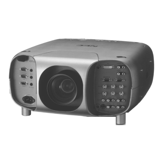
Page 10: Getting To Know Your Gt1150 Projector
Getting to Know Your GT1150 Projector Lens hood Remote sensor Terminal panel (Left) R IG AC INPUT Connect the supplied power cable’s three-pin plug here. Lens (optional) Lens hood cap D V I L /M L /M N IT R /C... - Page 11 Depression for foot (4 locations) Remote sensor Carrying handle Speaker (Left) Lamp cover Remote sensor Speaker (Right) Air filter Ventilation (inlet) E – 3...
-
Page 12: Attaching The Lens Hood Cap To The Lens Hood With The Supplied String And Rivet
Attaching the lens hood cap to the lens hood with the supplied string and rivet Lens hood cap 1. Thread the string through the hole on the lens hood cap. String 2. Use the rivet to attach the string to the bottom of the projector. Rivet Carrying the Projector Always carry your projector by the handle. -
Page 13: Top Features
Top Features 1. Power Button (ON / STAND BY) Use this button to turn the power on and off when the power is sup- plied and the projector is in standby mode. NOTE: To turn off the projector, press and hold this button for a minimum of two seconds. -
Page 14: Front Terminal Panel (Right
RGB 2 or DVI analog input source. 6. RGB 1 Input Connectors (BNC) Connect R,G,B,H (Horizontal sync) and V (Vertical sync) outputs of external equipment such as the NEC ISS-6020Switcher. If using a component with a combined sync (SYNC) output, connect it to the H/V terminal. When using... -
Page 15: Front Terminal Panel (Left
Sleave (ground. 0V) PC Card Viewer When the GT1150 is powered OFF the screen trigger stops sending a low voltage trigger to the screen controller and the screen will go up. NOTE: Screen Controllers are supplied and supported by screen manufactures. -
Page 16: Remote Control Features
Remote Control Features POWER MENU ADDRESS ENTER ADJUST IMAGE PICTURE WHITE BAL. PROJECTOR UNDO CANCEL TEST INFO. HELP POSITION PIXEL AUTO LENS MUTE SHUTTER PICTURE SOUND KEYSTONE AMPLITUDE ENTRYLIST MAGNIFY FOCUS ZOOM LENS 1. POWER ON Button Press this button to turn on the projector when the power is supplied and the projector is in standby mode. - Page 17 10. UNDO Press to return the adjustments and settings to the previous condition. While pressing and holding CTL, pressing this button clears the entire menus or adjustment/setting screen. At this time the adjustments/set- tings are stored in memory except the items on the setting screen with "OK"...
-
Page 18: Remote Control Precautions
Remote Control Precautions • The remote control system may not function when direct sunlight or strong illumination strikes the remote control sensor of the main unit, or when there is an obstacle in the path. • When remote control buttons are pressed and held, projector’s func- tion keys may not operate. -
Page 19: Using The Remote Control In Wired Operation
Using the Remote Control in Wired Operation Connect one end of the supplied remote cable to the REMOTE 2 IN mini jack and the other end to the remote jack on the remote control. REMOTE PC CONTROL REMOTE 1 SC, TRIGGER Remote cable (supplied) AC IN Terminal panel (Left) -
Page 20: Installation
2. INSTALLATION This section describes how to set up your GT1150 projector and how to connect video and audio sources. Setting Up Your GT1150 Projector Your GT1150 Projector is simple to set up and use. But before you get started, you must first: 1. -
Page 21: Lens Shift Adjustable Range
Lens Shift Adjustable Range Desktop/Front Vertical Normal Position Ceiling/Front Vertical Normal Position Horizontal Normal Position Lens Shift Range for Desktop and Ceiling Mount Application The diagram below shows the location of the image position in the lens. The lens can be shifted within the shaded area as shown using the normal projection position as a starting point. -
Page 22: Optional Lens Installation
Optional Lens Installation This section describes how to install the lens. Before installation * Determine the optional lens to be used to obtain a desired projection distance. There are four optional lenses available: GT10RL (Fixed short throw lens) GT19ZL, GT13ZL and GT34ZL (Zoom lens) * Press the power button (ON/STAND BY) on the projector or POWER OFF button on the remote control, wait ONE minute for the cooling fan to stop, then disconnect the power cable. - Page 23 3. Mount the lens unit on the projector and connect the extension cable attached to the projector. 1 Remove the lens cap from the rear end of the lens unit. 2 Insert the lens unit so that the 4 screws on the lens unit are properly lined up with the 4 holes on the lens mount. 3 Secure the 4 screws using the hexagonal driver.
-
Page 24: Setting Up For Double Stacking In Link Mode
Setting up for Double Stacking in Link Mode NOTE: Up to two units can be gravity stacked without external support. In some cases, however, two images will not align on the screen correctly. This will become more apparent when displaying small text and detailed graphics. CAUTION: To prevent the projectors from falling, install them in a place and fasten them in a way with sufficient strength to support the two projectors. -
Page 25: Projector Orientation
Link Mode 6-6 This completes the Link Mode adjustment procedure. NOTE: The optional lenses for GT1150 have different geometrical distortions in wide zoom and tele. Select the best zoom position for stacking where the geo- metrical distortion is as small as possible. See page E-70 for the recommended throw distances and other notes. - Page 26 WARNING • Installing your projector on the ceiling must be done by a qualified technician. Contact your NEC dealer for more information. * Do not attempt to install the projector yourself. • Only use your projector on a solid, level surface. If the projector falls to the ground, you can be injured and the projector severely dam- aged.
-
Page 27: Basic Operation
3. BASIC OPERATION Connecting the Power Cable and Turn on the Projector Before you turn on your projector, ensure that the computer or video source is turned on and that your lens cap is removed. 1. Connect the supplied power cable to the projector. Plug the supplied power cable in the wall outlet. -
Page 28: About Startup Screen
To turn off the projector: First press the Power (ON/STANDBY) button on the projector cabinet or the POER OFF button on the remote control for a minimum of two seconds. The power indicator will glow orange. After the projector turns off, the cooling fans keep operating for ONE minute. -
Page 29: Set Up The Projector
Set up the projector 1. Turn on the projector 2. Select your type of projection: Desktop front, ceiling rear, desktop rear, and ceiling front. 3. Display the test pattern by pressing the TEST button on the re- mote control or using the menu. TEST 4. -
Page 30: Other Adjustments
Other adjustments Rotate the projector to make the image square. Use keystone correction for proper adjustment. Rotate the four feet to make the image square to the screen. Each of the feet height can be changed up to 20 mm or at angles up to 3.5 degrees. -
Page 31: Connections
When used in standalone operation Connecting Your VCR Or Laser Disc Player Use common RCA cables (not provided) to connect your VCR or laser disc player to your GT1150 Projector. To make these connections, simply: 1. Turn off the power to your projector and VCR or laser disc player. -
Page 32: Connecting Your Dvd Player With Component Output
Connecting Your DVD Player with Component Output Use the optional Component V cable to connect your DVD player with the component output to your GT1150 Projector. To make these connections, simply: 1. Turn off the power to your projector and DVD player. -
Page 33: Connecting Your Pc Or Macintosh Compute
Connecting Your PC Or Macintosh Computer Connecting your PC or Macintosh computer to GT1150 Projector will enable you to project your computer's screen image for an impressive presentation. To connect to a PC or Macintosh : 1. Turn off the power to your projector and computer. -
Page 34: Connecting An External Monitor
Connecting an External Monitor You can connect a separate, external monitor to your GT1150 projec- tor to simultaneously view on a monitor the RGB analog, DVI analog, or component image you're projecting. To do so: 1. Turn off the power to your projector, monitor and computer. -
Page 35: Connecting To A Single Workstation
Connecting to a Single Workstation You can connect a workstation to your GT1150 projector. To do so: 1. Turn off the power to your projector and workstation. 2. Use a BNC x 5 cable to connect your workstation and the RGB 1 connectors on your projector. -
Page 36: When Used With One Switcher (Iss-6020/Iss-6020G
When Used with One Switcher (ISS-6020/ISS-6020G) Up to 10 input signals can be accepted when the projector is connected to one Switcher. Using the projector with the Switcher allows easy adjustment and signal selection. MONITOR OUT RGB 1 R/Cr VIDEO 1 L/MONO R VIDEO 2 L/MONO... -
Page 37: When Used With Two Or More Switchers (100 Inputs
When Used with Two or More Switchers (100 Inputs) Up to 100 inputs can be accepted using the NEC ISS-6020 Switcher. How to make connections: 1 Connect the REMOTE 1 terminal of the master Switcher to the REMOTE 1 of the projector using the optional control cable (15p-15p/CTL-6010). -
Page 38: Set The Dip Switch (S8601) Of The Switcher As Follows
Set the DIP switch (S8601) of the Switcher as follows: NOTE: Slave numbers 1 to 10 must correspond to the master’s slot numbers 1 to 10. ISS-6020 Output to ISS-6020G Master The Projector Slave 1 Slot 1 of the Master Slave 2 Slot 2 of the Master Slave 3... -
Page 39: Remote 1 Connector
REMOTE 1 Connector This connector is used for either connecting the ISS-6020/ISS-6020G Switcher or a third party external control device. When the Switcher is used, connect it with the optional control cable (15-15 pin; 50 ft./16m; CTL-6010) to this connector. When used with the Switcher. - Page 40 When used in stand alone operation. Pin No. SHORT/OPEN 12pin 11pin 4,8,12,11 OPEN OPEN OPEN OPEN OPEN OPEN SHORT OPEN SHORT OPEN SHORT OPEN OPEN SHORT OPEN SHORT OPEN SHORT OPEN SHORT SHORT SHORT SHORT SHORT * When the combinations other than specified in the above table are selected, the input will be forcefully switched to RGB 1.
-
Page 41: Operating Multiple Projector With Remote Control
Operating Multiple Projector with Remote Control You can operate multiple projectors with the same remote control in wireless operation. To do so: 1. Select [Advanced Menu] [Projector Options] [Setup] [Page 6] [Projector ID] and assign an ID number to each projector. See also page E-49. 2. -
Page 42: Using The Pc Control Connectors
Using the PC CONTROL connectors The Link mode function allows you to adjust or set multiple projectors using the RGB 2 and the PC CONTROL connectors. Connection for Double Stacking in Link Mode Connect source equipment to the master projector. Master projector PC CONTROL Bi-directional RS-232C... -
Page 43: Operation
5. OPERATION This section describes how to select a computer or video source, ad- just the picture and sound, edit a signal and adjust all other settings and adjustments for proper projector set-up. General Controls Before you turn on the projector ensure that the computer or video source is turned on and that the lens hood cap is removed. -
Page 44: Customizing Basic/Custom Menu
Customizing Basic/Custom Menu The Basic/Custom menu can be customized to meet your requirements. Selecting a menu item from the “Basic/Custom Menu Edit” list, allows you to custom tailor the menu items to your needs. 1. Select “Basic/Custom Menu Edit” to display the “Basic/Custom Menu Edit”... -
Page 45: List Of Direct Button Combinations
List of Direct Button Combinations CTL+ SOURCE (1-10) CTL+ ENTER (While displaying Entry list) CTL+CANCEL CTL+ UNDO CTL+ While using zoom on remote control: CTL+ (BS) CTL+MUTE OSD SOURCE (1-10) in SW Level mode CTL+ MENU (ADDRESS) CTL+ IMAGE (PROJECTOR) CTL+ POSITION (LENS) CTL+ KEYSTONE (R) CTL+ AMPLITUDE (G) -
Page 46: Menu Tree
Menu tree Advanced Menu Source Select Picture Volume Image Options Projector Options Tools Help Test Pattern Cross Hatch, Gray Bars, Color Bars, Black Raster,Gray Raster, White Raster, ANSI Checker, Focus, Aspect Ratios Red/Green/Blue When Switcher Control is turned on: Switcher Entry List 1.RGB1 2.RGB2... -
Page 47: Menu Elements
Menu Elements Title bar Highlight Check box Tool bar Menu windows or dialog boxes typically have the following elements: Title bar: Indicates the menu title. Highlight: Indicates the selected menu or item. Solid triangle: Indicates further choices are available. A highlighted triangle indicates the item is active. Tab: Indicates a group of features in a dialog box. -
Page 48: Menu Descriptions & Functions
Menu Descriptions & Functions Source Select When Switcher Control is set to "Standalone", you can select a video source such as a VCR, DVD player, laser disc player, computer, or document camera depending on what is connected to your inputs, or PC Card Viewer (PC card installed). -
Page 49: Picture
Select “Source Name” and press ENTER to display the Source Name Edit window. You can change source name on this window. Select "Input Terminal" and press ENTER to display the Input Terminal window. You can change input terminal on this window. Select “Direct Key”... -
Page 50: Image Options
Image Options Keystone This feature corrects the keystone (trapezoidal) distortion to make the top of the screen longer or shorter to be the same as the bottom. Use the buttons on the slide bar to correct the keystone (trapezoidal) distortion. Keystone distortion NOTE: 1) The maximum keystone angle that can be corrected is 30 degrees upward... -
Page 51: Color Matrix
Color Matrix (available for component video signal only) First select an appropriate color matrix to fit your component signal for HDTV or SDTV. Then select an appropriate matrix type from B-Y/R-Y, Cb/Cr or Pb/Pr. White Balance (not available for PC Card Viewer) This allows you to adjust the white balance. -
Page 52: Video Filter
Video Filter (when Auto Adjust is off) This function reduces video noise. Select On/Off with the Select button. On ... The low-pass filter is applied. Off ... The filter is removed. Screen adjustments are possible even when the filter is On. Overscan (RGB only) You can select overscan percentage for RGB signal. -
Page 53: Menu
1. Open the On/OFF Timer window. 2. Select EDIT and press ENTER on the remote control to open the EDIT window. 3. Set the Week, Day, On-Time and Off-Time using the Select buttons and Source buttons (1 thru 10). To cancel the on-time or off time, use Delete. -
Page 54: Display Select
[Page 2] Display Select: You can choose the desired status information to be displayed on the screen. The desired status information will be displayed each time you switch between sources. Date Format: Eight display formats can be selected. This date format sets the current date that appears on the upper left corner of the screen. -
Page 55: Setup
Setup Enables you to set operating options. Press "OK" to save your changes for all the features of Page1, Page2, Page3, Page 4, Page5 and Page6. [Page 1] Orientation: This reorients your image for your type of projection. The options are: desktop front projection, ceiling rear projection, desktop rear projection, and ceiling front projection. -
Page 56: Signal Select(Rgb Connector
When "Auto Adjust" is set to "On", the projector automatically de- termines the best resolution for the current RGB input signal to project an image using NEC's Advanced AccuBlend Intelligent Pixel Blending Technology. The image can be automatically adjusted for position and stability;... -
Page 57: Remote Sensor
Standalone. See page E-16 for setting up for double stacking in link mode. Switcher Control This feature sets the projector in communication with the NEC ISS- 6020 Switchers. Stand Alone ... Use the projector in stand alone operation. -
Page 58: Tools
* Once you have changed the background from the NEC logo to another, you cannot return the logo to background even by using Factory Default. To do so, repeat the above steps. The NEC logo file is included on the sup- plied CD-ROM (/logo/nec_b_x.jpg). -
Page 59: Help
Help Contents: Provides an online help about how to use the menus. An under- lined link means that you can move to an adjustment item directly. Selecting the underlined link and pressing ENTER moves to the corresponding adjustment item. NOTE: The Help Menu may not be displayed correctly when a UXGA signal is displayed. -
Page 60: Using The Pc Card Viewer Function
Using the PC Card Viewer function NOTE: When using the supplied software (CD-ROM) The software is designed to use with a personal computer only. Do not play the software on CD player. Doing so could cause damage to speakers. Features The Viewer feature allows slides stored on a PC memory card (re- ferred to as PC card in this manual) to be displayed on the projector. -
Page 61: Installing The Pc Card Viewer Software
PC Card Viewer Utility. To start PC Card Viewer PPT Converter: * Select PC Card Viewer PPT Converter from NEC Projector Tools. Basic Operation of the PC Card Viewer Software PC Card Viewer Utility is an application for editing documents, con- verting them into slides and storing them on PC cards as playback data (indexes) for presentations using projectors. -
Page 62: Operating The Pc Card Viewer Function From The Projector (Playback
Operating the PC Card Viewer Function from the Projector (playback) This section describes the operation for showing slides of presentation documents created using the PC Card Viewer function with the projec- tor. It is also possible to make slides directly from the images projected with the projector. - Page 63 When the tool bar is not displayed: Press select or , or the FOLDER LIST button on the optional remote control to display folders from a PC card in the projector’s PC Card slot. Multi cursor (blue marks) Folder Folder SLIDE Folder Serial number of folder...
-
Page 64: Capturing Images Displayed On The Projector
Capturing Images Displayed on the Projector Storing images displayed on the projector on the PC card Preparations: Insert the PC card into the card slot. Insert the PC card with the side with the insertion direction arrow on the top. * Press the eject button to eject the card. -
Page 65: Uninstalling The Pc Card Viewer Software
Uninstalling the PC Card Viewer Software Even if you do now know the PC Card Viewer software's file names or where they are stored, the PC Card Viewer software files can be easily removed from the system using the "Install/Uninstall Applications" con- trol panel in Windows. -
Page 66: Maintenance
: Eco mode) of use, the lamp bulb may shatter, and pieces of glass may be scattered in the lamp housing. Do not touch them as the pieces of glass may cause injury. If this happens, contact your NEC dealer for lamp replacement. -
Page 67: Cleaning Or Replacing The Filter
Cleaning or Replacing the Filter The air-filter sponge keeps the inside of the MultiSync GT1150 Projec- tor free from dust or dirt and should be cleaned after every 100 hours of operation (more often in dusty conditions). If the filter is dirty or clogged, your projector may overheat. -
Page 68: Remplacement De La Lampe
Ne les touchez pas car elles peuvent vous blesser. Dans ce cas, contactez votre revendeur NEC afin de procéder au remplacement de la lampe. Pour remplacer la lampe: 1. -
Page 69: Nettoyage Ou Remplacement Du Filtre
Nettoyage ou remplacement du filtre Le coussin éponge du filtre à air maintient l’intérieur du projecteur GT1150 à l’abri de la poussière ou de la saleté et doit être nettoyé toutes les 100 heures d’utilisation (plus souvent dans les endroits poussiéreux). -
Page 70: Troubleshooting
7. TROUBLESHOOTING This section helps you resolve problems you may encounter while setting up or using the projector. Power/ Status Light Messages Condition Standby Normal ON-Timer setting Cooling down Lamp in High-Bright mode Lamp in Eco mode 3 minutes after lamp is turned on in Eco mode Lamp has reached its end of life (1500 hours or over) - Page 71 Selecting a new signal that is close to one of the listed signals in horizontal and vertical frequency may not display the image correctly because the new signal is considered as one of the registered signals listed in the Entry List. (In this case the Auto Adjust feature may not work correctly.) To use both signals, use different input terminal (RGB 1 or RGB 2) respectively, or assign specific remote keys for signals.
-
Page 72: Specifications
8. SPECIFICATIONS This section provides technical information about the GT1150 Projector’s performance. Model Number GT1150 Optical LCD Panel 1.3" p-Si TFT active-matrix with Micro Lens Array, 1024 768 native resolution up to 1600 1200 with Advanced AccuBlend Technology Lamp 250 W NSH lamp... -
Page 73: Mechanical
LCD panels are inherently susceptible to bad pixels. The LCD panel may have pixel failures at the rate of 0.01% or less. We provide information about our projectors through the World Wide Web at http://www.nec-pj.com/ The specifications are subject to change without notice. -
Page 74: Cabinet Dimensions
Cabinet Dimensions 7.7" (195) 8.3" (210) Optional Accessories Lens Optional lens (Fixed short throw: 1.0) Optional lens (Zoom: 1.3 – 1.6) Optional lens (Zoom: 1.8 – 2.4) Optional lens (Zoom: 3.4 – 5.2) Lamp Replacement lamp Ceiling Mount Kit for ceiling mount installation Expansion module LAN module Remote Control Presentation remote control kit... -
Page 75: D-Sub Pin Assignments
D-Sub Pin Assignments Mini D-Sub 15 Pin Connector (RGB2) Signal Level Video signal : 0.7Vp-p (Analog) Sync signal : TTL level Pin No. RGB Signal (Analog) Green or Sync on Green Blue Ground Ground Red Ground Green Ground Blue Ground No Connection Sync Signal Ground Ground... -
Page 76: List Of Menu Items Available In Link Mode
List of Menu Items Available in Link Mode See the table below for available functions in the analog link mode. Each letter used in the table below indicates the following: Master projector valid invalid valid adjustable independently NOTE: The DVI connector does not support digital signal in the Link Mode. Function Menu Source Select... -
Page 77: Timing Chart
Timing Chart Y / N Signal Resolution ( Dots ) NTSC SECAM VESA VESA VESA VESA VESA VESA VESA VESA VESA VESA VESA 1024 VESA 1024 VESA 1024 1024 1024 VESA 1024 VESA 1024 VESA 1152 1152 1152 1152 VESA 1280 1280 1024... -
Page 78: Pc Control Codes
1. Note : Gravity Stacking Two GT1150 Projectors The optional lenses for GT1150 have different geometrical distortions in wide zoom and tele. Select the best zoom position for stacking where the geometrical distortion is as small as possible. The recommended throw distances are as follows:... - Page 79 Printed in Japan 7N8P0112...