Table of Contents
Advertisement
SERVICE
MICROWAVE OVEN
MICROWAVE OVEN
BASIC : SMH7174WD
SMH7174BD
MODEL : SMH7174WE
SMH7174BE
Manual
1. Precaution
2. Specifications
3. Operating Instructions
4. Disassembly and Reassembly
5. Alignment and Adjustments
6. Troubleshooting
7. Exploded Views and Parts List
8. PCB Diagrams
9. Schematic Diagrams
10. Reference
CONTENTS
Advertisement
Table of Contents

Related Manuals for Samsung SMH7174WE


Summary of Contents for Samsung SMH7174WE
-
Page 1: Microwave Oven
MICROWAVE OVEN BASIC : SMH7174WD SMH7174BD MODEL : SMH7174WE SMH7174BE SERVICE Manual MICROWAVE OVEN CONTENTS 1. Precaution 2. Specifications 3. Operating Instructions 4. Disassembly and Reassembly 5. Alignment and Adjustments 6. Troubleshooting 7. Exploded Views and Parts List 8. PCB Diagrams 9. -
Page 2: Table Of Contents
Contents 1. Precaution ................1 1-1 Safety precautions . - Page 3 Contents 7-2 Main Parts List ..............29 7-3 Control &...
-
Page 4: Exposure To Excessive Microwave Energy
PRECAUTIONS TO BE OBSERVED BEFORE AND DURING SERVICING TO AVOID POSSIBLE EXPOSURE TO EXCESSIVE MICROWAVE ENERGY (a) Do not operate or allow the oven to be (c) Before turning on microwave power for operated with the door open. any service test or inspection within the (b) Make the following safety checks on all microwave generating compartments, ovens to be serviced before activating the... -
Page 5: Precaution
1. Precaution Follow these special safety precautions. Although the microwave oven is completely safe during ordinary use, repair work can be extremely hazardous due to possible exposure to microwave radiation, as well as potentially lethal high voltages and currents. 1-1 Safety precautions ( 1. -
Page 6: Special Servicing Precautions (Continued)
1-2 Special Servicing Precautions (Continued) 17. When checking the continuity of the witches or transformer, always make sure that the power is OFF, and one of the lead wires is disconnected. 18. Components that are critical for safety are indicated in the circuit diagram by shading, 19. -
Page 7: Specifications
2. Specifications 2-1 Table of Specifications TIMER 99 MINUTES 99 SECONDS POWER SOURCE 120V 60Hz POWER CONSUMPTION MICROWAVE : 1,650W OUTPUT POWER FROM 100 TO 1100W(10 LEVEL POWER) (IEC-705 TEST PROCEDURE) OPERATING FREQUENCY 2,450MHz MAGNETRON OM75P(10)ERHN COOLING METHOD COOLING FAN MOTOR OUTSIDE DIMENSIONS ”(W) x 15 ”(H) x 15... -
Page 8: Operating Instructions
3. Operating Instructions 3-1 Control Panel Sensor Reheat Power/Auto Defrost Sets weight of food to be defrosted. Sensor Cook Buttons Sensor settings to cook popular foods. Handy Helper, Kids Meals, Snack Bar Selects type of dish to be reheated. More/Less Increase or decrease cooking time. -
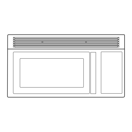
Page 9: Features & External Views
3-2 Features & External Views Door Ventilation Holes Oven Light Safety Interlock Holes Control Panel Handle Intake Holes Glass Tray Guide Roller Door Latches 758.9mm 398mm - 5 -... -
Page 10: Accessary
3-3 Accessary Installation Registration card Owner’s manual Instructions Top template Wall template Glass tray Roller guide ring Charcoal filter Hardware-kit Shelf Grease filters Exhaust adaptor - 6 -... -
Page 11: Installation
3-4 Installation The Microwave Oven is supported by a special bracket assembly (mounting system) supplied with the oven. The bracket assembly must be mounted to the wall with toggle bolts through the wall, and a lag screw into a wall stud. After the bracket assembly is installed, the unit can be slid over the two rails of the bracket assembly. -
Page 12: Reusable Grease Filters
3-5 Reusable Grease Filters The metal filter trap grease released by foods on the cooktop. They also prevent flames from foods on the cooktop from damaging the inside of the microwave. For this reason, the filters must ALWAYS be in place when the hood the vent fan is used. -
Page 13: Disassembly And Reassembly
4. Disassembly and Reassembly MAGNETRON, MOTOR ASSEMBLY, VENT BLOWER AND HIGH VOLTAGE TRANSFORMER Oven must be removed from wall. REMOVING OVEN FROM WALL (2 PEOPLE REQUIRED) Oven is hooked on metal tabs at bottom of wall mounting plate and to cabinet by (3) top cabinet bolts. 4-1 Replacement of High Voltage Transformer and Fan Motor Assembly. -
Page 14: Replacement Of Door Assembly
4-3 Replacement of Door Assembly 4-3-1 Removal of Door Assembly Remove hex bolts securing the upper hinge and lower hinge. Then remove the door assembly. Door "A" Door "C" 4-3-2 Removal of Door “E” Door “E” Following the procedure as shown in the figure, insert and bend a thin metal plate between Door “E”... -
Page 15: Reassembly Test
4-3-4 Reassembly Test After replacement of the defective component parts of the door, reassemble it and follow the instruc- tions below for proper installation and adjustment so as to prevent an excessive microwave leakage. 1. When mounting the door to the oven, be sure to adjust the door parallel to the bottom line of the oven face plate by moving the upper hinge and lower hinge in the direction necessary for proper alignment. -
Page 16: Replacement Of Stirrer Motor
4-6 Replacement of stirrer motor 1. Disconnect power and remove grille screws(2). 2. Remove grille and the bracket duct upper screw(1). 3. Remove the bracket duct upper and disconnect the stirrer motor wire. 4. Remove stirrer motor screws(1) and lift up stirrer motor after turn left. -
Page 17: Replacement Of Control Circuit Board
4-8 Replacement of Control Circuit Board 4-8-1 Removal of Control Box 1. Disconnect power and remove grille. 2. Remove a screw securing the control box assembly. 3. Be sure to ground any static electric charge in your body and never touch the control circuit. 4. -
Page 18: Alignment And Adjustments
5. Alignment and Adjustments PRECAUTION 1. High voltage is present at the high voltage terminals during any cook cycle. 2. It is neither necessary nor advisable to attempt measurement of the high voltage. 3. Before touching any oven components or wiring, always unplug the oven from its power source and discharge the high voltage capacitor. -
Page 19: High Voltage Capacitor
5-4 High Voltage Capacitor 1. Check continuity of the capacitor with the meter set at the highest resistance scale. 2. Once the capacitor is charged, a normal capacitor shows continuity for a short time, and then indicates 9MΩ. 3. A shorted capacitor will show continuous continuity. 4. -
Page 20: Vent Exhaust Blower Motor
5-8 Vent Exhaust Blower Motor THIS COMPONENT REQUIRE REMOVAL OF MICROWAVE OVEN FROM INSTALLATION FOR SERVICING. The blower is a three speed (TURBO-HI-LO) capaci tor run blower assembly located on top of the micro- wave oven. The blower is operated by low voltage relays located on the smart board. -
Page 21: Thermal Cutout(Tco's)
5-9 Thermal Cutout(Tco’s) There are 4 different thermal cutouts in this unit with 4 different purposes. They are : 1. Oven thermal cutout (flame sensor), on cavity top. 2. Hood thermal cutout, inside control area on duct. 3. Bottom thermal cutout, on floor of control area. 4. -
Page 22: Hood Thermal Cutout
5-9-3 Hood Thermal Cutout This cutout will protect the touch control from exces- sive heat by turning the vent fan on at low speed. If the HOOD THERMAL CUTOUT surface units of the range are used for long periods of time heat will build up and could damage the micro- wave control. -
Page 23: Magnetron Thermal Cutout
5-9-5 Magnetron Thermal Cutout The magnetron thermal cutout is located above the MAGNETRON THERMAL CUTOUT leads to the magnetrons. It is designed to prevent damage to the magnetron if an overheated condition develops in the tube to cooling fan failure, obstructed air ducts, dirty or blocked air intake. -
Page 24: Output Power Of Magnetron
5-11 Output Power of Magnetron CAUTION MICROWAVE RADIATION PERSONNEL SHOULD NOT ALLOW EXPOSURE TO MICROWAVE RADIATION FROM MICROWAVE GENERA- TOR OR OTHER PARTS CONDUCTING MICROWAVE ENERGY. The output power of the magnetron can be measured by performing a water temperature rise test. Equipment needed : * Two 1-liter cylindrical borosilicate glass vessel (Outside diameter 190 mm) * One glass thermometer with mercury column... -
Page 25: Procedure For Measurement Of Microwave Energy Leakage
; Samsung Electronics America, Inc. Headquarters 105 Challenger Road Ridge field Pack, New Jersey 07660-0511 5-15-2 At least once a year have the microwave energy survey meter checked for accuracy by its manufacturer. -
Page 26: Troubleshooting
6. Troubleshooting PRECAUTION 1. CHECK GROUNDING BEFORE CHECKING FOR TROUBLE. 2. BE CAREFUL OF THE HIGH VOLTAGE CIRCUIT. 3. DISCHARGE THE HIGH VOLTAGE CAPACITOR. 4. WHEN CHECKING THE CONTINUITY OF THE SWITCHES OR TRANSFORMER, DISCONNECT ONE LEAD WIRE FROM THESE PARTS AND THEN CHECK CONTINUITY WITHOUT THE POWER SOURCE ON. TO DO OTHERWISE MAY RESULT IN A FALSE READING OR DAMAGE TO YOUR METER. - Page 27 6-1 Electrical Malfunction(continued) SYMPTOM CAUSE CORRECTIONS Oven lamp and fan motor turn 1. Misadjustment or loose wiring Adjust door and latch switches. of primary latch switch 2. Defective primary latch switch Oven can program but timer 1. Open or loose wiring of secondary i Adjust door and interlock switches.
-
Page 28: Error Code Numbering Rule
6-2 Error Code Numbering Rule 1. ERROR CODE NUMBERING RULE is applied to a microwave oven and an oven.(CMO, OTR, Grill, Convection, Commercial etc.) 2. All sensors and devices have their own number. ex) Gas Sensor = 1, Temp. Sensor = 2, ... 3. - Page 29 6-2 Error Code Numbering Rule(continued) Error Code List Gas Sensor Error Code Gas Sensor Error Case (E-1X) E-11 Open E-12 Short E-13 T1 Max Time Error E-14 Dry Up / No Load Temp Sensor Error Code Temp. Sensor Error Case (E-2X) E-21 Open E-22...
- Page 30 6-2 Error Code Numbering Rule(continued) Eeprom Error Error Code EEPROM Error Case (E-5X) E-51 Open (Sense Failure) E-53 Read/Write Error E-54 Zero not to be set Humidity Sensor Error Code Humidity Sensor Error Case (E-6X) E-61 Open E-62 Short E-63 T1 Max Time Error Others Error Code...
-
Page 31: Exploded Views And Parts List
7. Exploded Views and Parts List 7-1 Exploded Views P090 P125 M060 P087 P088 U008 P007 P089 P091 P006 P012 M061 T017 P013 P014 T001 T032 P032 M015 X008 P097 T030 M219 C089 P034 M068 P039 P124 M024 M001 P015 M036 P016 P122... -
Page 32: Main Parts List
7-2 Main Parts List (S.N.A : SERVICE NOT AVAILABLE) LEVEL Code No. Description Specification Q’ty Remark M036 4713-001013 LAMP-INCANDESCENT 130V,-,40W,ORG,E17/20, DUCT UPPER M038 DE26-00082D TRANS H.V SHV-U1870B,120V,60HZ,2460/2220 M024 DE31-00029B MOTOR VENTILATION SMV-460UA-1,SMH7175WE/ M049 DE31-10172A MOTOR-SYNCHRONOUS M2HJ24Z709,ST-16F,21V, M050 DE31-10173A MOTOR-SYNCHRONOUS M2HJ29A709,ST-16F,21V, M029 DE47-20007A THERMOSTAT... -
Page 33: Main Parts List
7-2 Main Parts List (S.N.A : SERVICE NOT AVAILABLE) LEVEL Code No. Description Specification Q’ty Remark W002 DE96-00491A ASSY-WIRE HARNESS A SMH7175WE/XAA,120V/6 U001 DE97-00360B ASSY-BASE BOTTOM SMH7175,GRY,INCANDESCAN (WE) U001 DE97-00360A ASSY-BASE BOTTOM SMH7175,INCANDESCENT LA (BE) M036 4713-001013 LAMP-INCANDESCENT 130V,-,40W,ORG,E17/20, U003 DE47-00006A HOLDER-LAMP -,250V,75W,250X187 2POLE,OTR... -
Page 34: Control & Door Parts List
DE63-00139A COVER-HANDLE SMH7175,PC,T2.0,BLK,-,-,-,- (BE) D019 DE64-00761B HANDLE-DOOR SMH7175,PC,T2.0,WHT,-,-,-,- (WE) D019 DE64-00761A HANDLE-DOOR SMH7175,PC,T2.0,-,-,-,BLK,- (BE) C082 DE94-00933P ASSY CONTROL-BOX -,SMH7174WE/XAA,WHITE,V (WE) C082 DE94-00933N ASSY CONTROL-BOX -,SMH7174BE/XAA,BLACK,V (BE) C089 DE39-40673A WIRE HARNESS-H 120V60HZ,OTR6 ALL MODEL,G C001 DE94-00939P ASSY CONTROL-PANEL 120V/60HZ,SMH7174WE/X (WE) C001... -
Page 35: Standard Parts List
7-4 Standard Parts List (S.N.A : SERVICE NOT AVAILABLE) Level Code No. Description Specification Q’ty SA/SNA Remark DE60-20066A BOLT-FLAT UNF1/4,L110,MSWR10,-,-,OTR6,-, DE60-20022A BOLT-TOGGLE MSWR,W3/16X75,-,-,-,-,-,-,- DE60-30015A NUT-FLANGE M5,P0.8,MSWR10,FEFZY,-,-,-,-,- DE60-30063A NUT-MOUNTING -,M6.3,S10C,ZNC,YEL,-,-,-,- DE60-30022A NUT-TOGGLE SBC1,ZPC2,WHT,-,-,-,-,-,- DE60-10082I SCREW-A -,-,-,-,2S-4X12,FEFZY,-,-,-,- ASSY HVC DE60-10082I SCREW-A -,-,-,-,2S-4X12,FEFZY,-,-,-,- BASE-P DE60-10082I SCREW-A... -
Page 36: Diagrams
8. P.C.B Diagrams 8-1 P.C.B Diagrams ( This Document can not be used without Samsung’s authorization ) 100nF ZD03 UZ5.1BSB CN05 SMW250-03V_WHT BZ01 CBE2220BA DSP1 SVM-07SS25 - 32 -... -
Page 37: Parts List
8-2 P.C.B Parts List (S.N.A : SERVICE NOT AVAILABLE) LEVEL Code No. Description Specification Q’ty SA/SNA Remark RAS-OTR7HV-03 ASSY PCB PARTS SMH7175,120V/60HZ 0204-001118 FLUX SV-95-1F,C19H29COOH,C3H7OH,-,1 1.33 2011-000777 R-NETWORK 47Kohm,5%,1/8W,A,SIP,8P,TP AR01 3501-000256 RELAY-POWER 110V,1200VA,10000MA,-,10MS,1 RY04 3501-001155 RELAY-MINIATURE 24VDC,200MW,3000MA,1FORM RY11 3708-001550 CONNECTOR-FPC/FC/PIC 16P,1.25mm,STRAIGHT CN01 3711-000879... - Page 38 8-2 P.C.B Parts List(continued) (S.N.A : SERVICE NOT AVAILABLE) LEVEL Code No. Description Specification Q’ty SA/SNA Remark DE39-60001A WIRE-SO COPPER PI0.5,SN,T,52MM,TAPING_WI DE41-00309A PCB-MAIN RAS-OTR7HV,FR-1,1,-,T1.6,197*19 1203-001037 IC-VOLTAGE REGULATOR 78L05,SOT-89,3P,185 IC05 2401-002216 C-AL 2200uF,20%,35V,GP,TP,16x25,7.5 DE13-20009A KA7533,DIP,-,-,-,-,- IC03 2004-005092 R-METAL 348KOHM,1%,1/8W,AA,TP,1.8X3.2MM 2001-000780 R-CARBON 470OHM,5%,1/8W,AA,TP,1.8X3.2MM 2004-004255 R-METAL...
-
Page 39: Schematic Diagrams
9. Wiring Diagrams Wiring Diagrams ( This Document can not be used without Samsung’s authorization ) - 35 -... - Page 40 9-1. Wiring Diagrams(continued) - 36 -...
-
Page 41: Reference
10. Reference 10-1 Model name standard Baoad Distin- Middle Distin- Product Full Nane Classification guisher Classfication guisher Code USA CMO CMO (Counter- USA CMO(EPOXY CAVITY) top MWO) UTC (Under The USA UTC Cabinet) Browner, Grill USA GRILL Convection USA CONVECTION Sensor USA CMO SENSOR DC MWO... -
Page 42: Customer Inquiry Cases And Countermeasures
• Close the door completely. => Press the Cancel but- ton. => Press the Start button. • Contact the nearest Samsung after-sales service cen- ter. Ground • Ground problem may • If the oven is placed in a humid area, buy an electric happen when the oven wire in a store selling electrical products. - Page 43 Accessory • Visit the nearest Samsung Service Center or local dealer to buy accessories. Before visiting, check the model name printed on the lower right side of the front panel of the oven.
- Page 44 © Samsung Electronics Co., Ltd. Aug. 2005 This Service Manual is a property of Samsung Electronics Co.,Ltd. Printed in Korea Any unauthorized use of Manual can be punished under applicable Code No. : DE68- 03971A International and/or domestic law.