Advertisement
Quick Links
Getting Started with R Series Intelligent DAQ
This document explains how to install and configure National Instruments 78xxR devices.
NI 78xxR Required Components
The following items are necessary to set up and use the NI PCI/PXI-78xxR:
❑
The following software packages:
–
LabVIEW 7.1 or later
–
LabVIEW FPGA Module 1.1 or later
–
NI-RIO 1.3 or later—included with the NI 78xxR
–
(Optional)
Note
The examples referenced in this document require LabVIEW 8.0 or later and NI-RIO 2.0
or later.
❑
Development computer or PXI/CompactPCI chassis and PXI/CompactPCI embedded controller
running Windows 2000/XP.
❑
At least one cable and device for connecting signals to the NI 78xxR.
Step 1. Install Application Software and Driver
Before installing the NI 78xxR, you need to install the application software and device driver.
Note
The NI PXI-7831R supports LabVIEW 7.0 or later, LabVIEW FPGA Module 1.0 or later,
and NI-RIO 1.0 or later. The NI PCI-7831R and NI PXI-7811R support NI-RIO 1.1 or later.
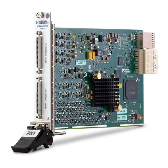
Figure 1. PCI and PXI R Series Devices
LabVIEW Real-Time Module 7.1 or later
Advertisement

Related Manuals for National Instruments NI 78xxR


Summary of Contents for National Instruments NI 78xxR
- Page 1 At least one cable and device for connecting signals to the NI 78xxR. Step 1. Install Application Software and Driver Before installing the NI 78xxR, you need to install the application software and device driver. Note The NI PXI-7831R supports LabVIEW 7.0 or later, LabVIEW FPGA Module 1.0 or later, and NI-RIO 1.0 or later.
- Page 2 You must install NI-RIO before installing the NI 78xxR. Unpacking The NI 78xxR is shipped in an antistatic package to prevent electrostatic discharge from damaging device components. To prevent such damage when handling the device, take the following precautions: •...
- Page 3 Double-click the Measurement & Automation icon on the desktop to open Measurement & Automation Explorer (MAX). Expand Devices and Interfaces. Verify that the device appears under Devices and Interfaces»RIO Devices. © National Instruments Corporation PCI System Slot Figure 2. Installing an NI PCI-78xxR Device I- 1...
-
Page 4: Step 3. Connect Signals
Step 3. Connect Signals Figure 4 shows the I/O connector pin assignments and locations for NI 781xR Digital R Series devices. Figure 5 shows the I/O connector pin assignments and locations for NI 78xxR Multifunction R Series devices. 68 34... - Page 5 Connections that exceed any of the maximum ratings of input or output signals on the NI 78xxR can damage the NI 78xxR and the computer or chassis. NI is not liable for any damage resulting from such signal connections. For the maximum input and output ratings for each signal, refer to the NI 781xR User Manual for NI 781xR Digital R Series devices or the NI 783xR User Manual for NI 78xxR Multifunction R Series devices.
-
Page 6: Connectivity Options
Connectivity Options Accessing the signals on the I/O connectors requires at least one cable and one signal accessory. Table 1 summarizes the National Instruments connectivity options available for use with the NI 78xxR device. Cable Connector SHC68-68-RMIO (NI Recommended) SHC68-68-RDIO... - Page 7 Step 4. Using Your NI 78xxR Device with a LabVIEW FPGA Example VI (NI 783xR/784xR/785xR Only) The NI-RIO driver installation includes a variety of example projects to help get you started. This section demonstrates how to use an existing LabVIEW FPGA example project to take an analog input measurement with the NI 78xxR device.
- Page 8 On the block diagram, right-click the Open FPGA VI Reference function and choose Select VI from the shortcut menu. In the Select VI dialog box, select Analog Input (FPGA).vi in the new target and click OK. In the Project Explorer window, right-click the original FPGA target and select Remove to delete it from the project.
- Page 9 Click Connector0/AO0 in the Project Explorer window and drag it into the second frame of the Flat Sequence structure on the block diagram of the FPGA VI. The FPGA I/O Node is created automatically. © National Instruments Corporation Getting Started with R Series Intelligent DAQ...
- Page 10 Right-click the input terminal of the new FPGA I/O Node and select Create»Control from the shortcut menu. Rename the control AO Voltage, as shown in the following block diagram. Save the VI, then right-click Analog Input (FPGA).vi in the Project Explorer window and select Compile from the shortcut menu to recompile the FPGA VI.
-
Page 11: Where To Go From Here
FPGA Module book in the LabVIEW Help—Select Help»Search the LabVIEW Help in LabVIEW to view the LabVIEW Help. Browse the FPGA Module book in the Contents tab for information about how to use the FPGA Module to create VIs that run on the NI 78xxR device. -
Page 12: Where To Go For Support
• NI 783xR User Manual—Describes the electrical and mechanical aspects of the NI 78xxR Multifunction R Series devices, contains information about R Series device operation and programming, and includes device specifications. To access this document, refer to manuals • NI 781xR User Manual—Describes the electrical and mechanical aspects of the NI 781xR Digital R Series devices, contains information about Digital R Series device operation and programming, and includes device specifications.