Table of Contents
Advertisement
Available languages
Available languages
Advertisement
Table of Contents

Related Manuals for MSI H55M-E32 series


Summary of Contents for MSI H55M-E32 series
- Page 1 H55M-E32/ H55M-E23/ H55M-E21 series MS-7636 (v3.x) Mainboard G52-76361XK...
-
Page 2: Trademarks
Alternatively, please try the following help resources for further guidance. ◙ Visit the MSI website for FAQ, technical guide, BIOS updates, driver updates, and other information: http://www.msi.com/index.php?func=service ◙ Contact our technical staff at: http://ocss.msi.com... -
Page 3: Safety Instructions
MS-7636 MS-7636 Safety Instructions ■ Always read the safety instructions carefully. ■ Keep this User’s Manual for future reference. ■ Keep this equipment away from humidity. ■ Lay this equipment on a reliable flat surface before setting it up. ■ The openings on the enclosure are for air convection hence protects the equipment from overheating. -
Page 4: Fcc-B Radio Frequency Interference Statement
Preface Preface FCC-B Radio Frequency Interference Statement This equipment has been tested and found to comply with the limits for a Class B digi- tal device, pursuant to Part 15 of the FCC Rules. These limits are designed to provide reasonable protection against harmful inter- ference in a residential installation. -
Page 5: Weee (Waste Electrical And Electronic Equipment) Statement
MSI will comply with the product take back requirements at the end of life of MSI-branded prod- ucts that are sold into the EU. - Page 6 MSI će poštovati zahtev o preuzimanju ovakvih proizvoda kojima je istekao vek trajanja, koji imaju MSI oznaku i koji su prodati u EU. Ove proiz- vode možete vratiti na lokalnim mestima za prikupljanje.
- Page 7 MSI si adeguerà a tale Direttiva ritirando tutti i prodotti marchiati MSI che sono stati venduti all’interno dell’Unione Europea alla fine del loro...
-
Page 8: Table Of Contents
Preface Preface Contents Copyright Notice .................... ii Trademarks ....................ii Revision History..................... ii Technical Support..................ii Safety Instructions ..................iii FCC-B Radio Frequency Interference Statement.......... iv WEEE (Waste Electrical and Electronic Equipment) Statement ....v English ...................... En-1 Mainboard Specifications ...................En-2 Quick Components Guide ..................En-4 Screw Holes .......................En-5 CPU (Central Processing Unit) ................En-6... - Page 9 MS-7636 MS-7636 Français ..................... Fr-1 Spécifications ......................Fr-2 Guide Rapide Des Composants ................Fr-4 Trous Taraudés ....................Fr-5 Processeur : CPU ....................Fr-6 Mémoire ......................Fr-10 Connecteurs d’alimentation ................Fr-12 Panneau arrière ....................Fr-13 Connecteurs ......................Fr-15 Cavalier ......................Fr-20 Emplacements ....................Fr-21 Réglage BIOS ....................Fr-22 Information De Logiciel ..................Fr-32 Русский...
-
Page 11: English
English H55M-E32/ H55M-E23/ H55M-E21 Series Europe version... -
Page 12: Mainboard Specifications
Processor Support ■ Intel Core™ i7, Core™ i5 (Lynnfield & Clarkdale), Core™ i3 and Pentium processor ® ® in the LGA1156 package (For the latest information about CPU, please visit http://www.msi.com/index. php?func=cpuform2) Base Clock ■ 133 MHz Chipset ■ Intel H55 chipset ®... - Page 13 ■ Micro-ATX (21.0 cm X 24.5 cm) Mounting ■ 6 mounting holes * If you need to purchase accessories and request the part numbers, you could search the product web page and find details on our web address http://www.msi.com/index. En-3...
-
Page 14: Quick Components Guide
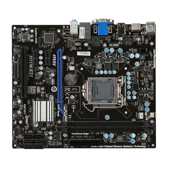
MS-7636 Mainboard MS-7636 Mainboard Quick Components Guide SYSFAN1, En-16 CPUFAN, En-16 JPWR2, En-12 CPU, En-6 SYSFAN2, En-16 DDR3, En-10 Back Panel, En-13 JPWR1, En-12 PCIE, En-21 JCI1, En-15 JBAT1, En-20 JTPM1, En-19 SATA1~6, En-15 PCI, En-21 JFP1, JFP2, En-17 JAUD1, En-18 JUSB1~3, En-17 JSP1, En-18 JLPT1, En-19... -
Page 15: Screw Holes
Screw Holes When you install the mainboard, you have to place the mainboard into the chassis in the correct direction. The locations of screws holes on the mainboard are shown as below. The side has to toward the rear, the position for the I/O shield of the chassis. -
Page 16: Cpu (Central Processing Unit
When you are installing the CPU, make sure to install the cooler to prevent overheating. If you do not have the CPU cooler, consult your dealer before turning on the computer. For the latest information about CPU, please visit http://www.msi.com/index. php?func=cpuform2... - Page 17 CPU & Cooler Installation When you are installing the CPU, make sure the CPU has a cooler attached on the top to prevent overheating. Meanwhile, do not forget to apply some thermal paste on CPU before installing the heat sink/cooler fan for better heat dispersion. Follow the steps below to install the CPU &...
- Page 18 MS-7636 Mainboard MS-7636 Mainboard Visually inspect if the CPU is seated Engage the load lever while pressing well into the socket. If not, take out down lightly onto the load plate. the CPU with pure vertical motion and reinstall. Alignment Key Secure the lever near the hook end Make sure the four hooks are in por- under the retention tab.
- Page 19 Align the holes on the mainboard with Press the four hooks down to fasten the heatsink. Push down the cooler the cooler. until its four clips get wedged into the holes of the mainboard. Turn over the mainboard to confirm Finally, attach the CPU Fan cable to that the clip-ends are correctly in- the CPU fan connector on the main-...
-
Page 20: Memory
MS-7636 Mainboard MS-7636 Mainboard Memory These DIMM slots are used for installing memory modules. For more information on compatible components, please visit http://www.msi.com/index.php?func=testreport DDR3 240-pin, 1.5V 48x2=96 pin 72x2=144 pin Dual-Channel mode Population Rule In Dual-Channel mode, the memory modules can transmit and receive data with two data bus lines simultaneously. -
Page 21: Installing Memory Modules
Installing Memory Modules The memory module has only one notch on the center and will only fit in the right orientation. Insert the memory module vertically into the DIMM slot. Then push it in until the golden finger on the memory module is deeply inserted in the DIMM slot. The plastic clip at each side of the DIMM slot will automatically close when the memory module is properly seated. -
Page 22: Power Supply
MS-7636 Mainboard MS-7636 Mainboard Power Supply ATX 24-pin Power Connector: JPWR1 This connector allows you to connect an ATX 24-pin power supply. To connect the ATX 24-pin power supply, make sure the plug of the power supply is inserted in the proper orientation and the pins are aligned. -
Page 23: Back Panel
Back Panel USB 2.0 Port (for H55M-E32) Mouse VGA Port RS-Out Line-In CS-Out Line-Out SS-Out DVI-D Port HDMI Port USB 2.0 Port USB 2.0 Port Keyboard (for H55M-E32) ▶ Mouse/Keyboard The standard PS/2 mouse/keyboard DIN connector is for a PS/2 mouse/keyboard. - Page 24 MS-7636 Mainboard MS-7636 Mainboard ▶ The standard RJ-45 LAN jack is for connection to Yellow Green/ Orange the Local Area Network (LAN). You can connect a network cable to it. Color LED State Condition Left Yellow LAN link is not established. On(Steady state) LAN link is established.
-
Page 25: Connectors
Connectors Serial ATA Connector: SATA1~6 This connector is a high-speed Serial ATA interface port. Each connector can connect to one Serial ATA device. * The MB layout in this figure is for reference only. SATA5 SATA6 SATA1_2 SATA3_4 Important Please do not fold the Serial ATA cable into 90-degree angle. Otherwise, data loss may occur during transmission. - Page 26 MS-7636 Mainboard MS-7636 Mainboard Serial Port Connector: JCOM1 This connector is a 16550A high speed communication port that sends/receives 16 bytes FIFOs. You can attach a serial device. Fan Power Connectors: CPUFAN,SYSFAN1~2 The fan power connectors support system cooling fan with +12V. When connecting the wire to the connectors, always note that the red wire is the positive and should be con- nected to the +12V;...
- Page 27 Front Panel Connectors: JFP1, JFP2 These connectors are for electrical connection to the front panel switches and LEDs. The JFP1 is compliant with Intel Front Panel I/O Connectivity Design Guide. ® JFP2 JFP1 Front USB Connector: JUSB1 / JUSB2 / JUSB3 This connector, compliant with Intel I/O Connectivity Design Guide, is ideal for con- ®...
- Page 28 MS-7636 Mainboard MS-7636 Mainboard S/PDIF-Out Connector: JSP1 This connector is used to connect S/PDIF (Sony & Philips Digital Interconnect Format) interface for digital audio transmission. * The MB layout in this figure is for reference only. S/PDIF-Out Bracket (optional) Front Panel Audio Connector: JAUD1 This connector allows you to connect the front panel audio and is compliant with Intel ®...
- Page 29 Parallel Port Header: JLPT1 This connector is used to connect an optional parallel port bracket. The parallel port is a standard printer port that supports Enhanced Parallel Port (EPP) and Extended Capabilities Parallel Port (ECP) mode. TPM Module connector: JTPM1 This connector connects to a TPM (Trusted Platform Module) module (optional).
-
Page 30: Jumper
MS-7636 Mainboard MS-7636 Mainboard Jumper Clear CMOS Jumper: JBAT1 There is a CMOS RAM onboard that has a power supply from an external battery to keep the data of system configuration. With the CMOS RAM, the system can automatically boot OS every time it is turned on. If you want to clear the system configuration, set the jumper to clear data. -
Page 31: Slots
Slots PCIE (Peripheral Component Interconnect Express) Slot The PCIE slot supports the PCIE interface expansion card. PCIE x16 Slot PCIE x1 Slot PCI (Peripheral Component Interconnect) Slot The PCI slot supports LAN card, SCSI card, USB card, and other add-on cards that comply with PCI specifications. -
Page 32: Bios Setup
MS-7636 Mainboard MS-7636 Mainboard BIOS Setup This chapter provides basic information on the BIOS Setup program and allows you to configure the system for optimum use. You may need to run the Setup program when: ■ An error message appears on the screen during the system booting up, and requests you to run BIOS SETUP. -
Page 33: Entering Setup
Entering Setup Power on the computer and the system will start POST (Power On Self Test) process. When the message below appears on the screen, press <DEL> key to enter Setup. Press DEL to enter SETUP If the message disappears before you respond and you still wish to enter Setup, restart the system by turning it OFF and On or pressing the RESET button. - Page 34 MS-7636 Mainboard MS-7636 Mainboard The Main Menu Once you enter BIOS CMOS Setup Utility, the Main Menu will appear on the screen. The Main Menu allows you to select from the setup functions and two exit choices. Use arrow keys to select among the items and press <Enter> to accept or enter the sub-menu.
- Page 35 ▶ M-Flash Use this menu to read/ flash the BIOS from storage drive (FAT/ FAT32 format only). ▶ Overclocking Profile Use this menu to save/ load your settings to/ from CMOS for BIOS. ▶ Load Fail-Safe Defaults Use this menu to load the default values set by the BIOS vendor for stable system performance.
- Page 36 Select [Ok] and press Enter to save the configurations and exit BIOS Setup utility. Important The configuration above are for general use only. If you need the detailed settings of BIOS, please see the English manual on MSI website. En-26...
- Page 37 Cell Menu Introduction : This menu is for advanced user who want to overclock the mainboard. Important Change these settings only if you are familiar with the chipset. ▶ Current CPU / DRAM / QPI Frequency These items show the current frequencies of CPU, Memory and QPI. Read-only. ▶...
- Page 38 MS-7636 Mainboard MS-7636 Mainboard ▶ Intel C-State C-state is a power management state that significantly reduces the power of the processor during idle. This field will appear after you installed the CPU which sup- ports c-state technology. ▶ C State Package Limit Setting This feild allows you to select a C-state level.
- Page 39 ▶ Intel Virtualization Tech This item is used to enable/disable the Intel Virtualization technology. For further information please refer to Intel’s official website. ▶ Intel VT-d Tech This item is used to enable/disable the Intel Virtualization Technology for Directed I/O (VT-d). For further information please refer to Intel’s official website. ▶...
- Page 40 MS-7636 Mainboard MS-7636 Mainboard ▶ DRAM Timing Mode Select whether DRAM timing is controlled by the SPD (Serial Presence Detect) EE- PROM on the DRAM module. Setting to [Auto] enables DRAM timings and the following “Advance DRAM Configuration” sub-menu to be determined by BIOS based on the con- figurations on the SPD.
- Page 41 ▶ CH1/ CH2 tRTP Time interval between a read and a precharge command. ▶ CH1/ CH2 tFAW This item is used to set the tFAW timing. ▶ Current CH1/ CH2 tdrRdTRd/ tddRdTRd/ tsrRdTWr/ tdrRdTWr/ tddRdTWr/ tsrWrTRd/ tddWrTWr/ tsrRDTRd/ tsrWrTWr These item show the advanced DRAM timings. ▶...
-
Page 42: Software Information
Utility menu : The Utility menu shows the software applications that the mainboard supports. Important Please visit the MSI website to get the latest drivers and BIOS for better system per- formance. En-32... -
Page 43: Deutsch
Deutsch H55M-E32/ H55M-E23/ H55M-E21 Serie Europe Version... -
Page 44: Spezifikationen
Prozessoren ■ Intel Core™ i7, Core™ i5 (Lynnfield & Clarkdale), Core™ i3 und Pentium Prozesso- ® ® ren für Sockel LGA1156 (Weitere Informationen finden unter http://www.msi.com/index. php?func=cpuform2) Haupt-Takt ■ 133 MHz Chipsatz ■ Intel H55 Chipsatz ® Speicher ■ 2 DDR3 DIMMs unterstützen DDR3 2133*(OC)/ 2000*(OC) /1600*(OC)/ 1333/ 1066 DRAM (max. - Page 45 ■ 1 PCI-Steckplatz, unterstützt 3,3V/ 5V PCI Bus Interface Form Faktor ■ Micro-ATX (21,0 cm X 24,5 cm) Montage ■ 6 Montagebohrungen * Wenn Sie für Bestellungen von Zubehör Teilenummern benötigen, finden Sie diese auf unserer Produktseite unter http://www.msi.com/index.php De-3...
-
Page 46: Komponenten-Übersicht
MS-7636 Mainboard MS-7636 Mainboard Komponenten-Übersicht SYSFAN1, De-16 CPUFAN, De-16 JPWR2, De-12 CPU, De-6 SYSFAN2, De-16 DDR3, De-10 Rücktafel, De-13 JPWR1, De-12 PCIE, De-21 JCI1, De-15 JBAT1, De-20 JTPM1, De-19 SATA1~6, De-15 PCI, De-21 JFP1, JFP2, De-17 JAUD1, De-18 JUSB1~3, De-17 JSP1, De-18 JLPT1, De-19 JCOM1, De-16... -
Page 47: Schraubenlöcher
Schraubenlöcher Wenn Sie das Mainboard zu installieren, müssen Sie das Mainboard in das Chassis in der korrekten Richtung setzen. Die Standorte von Schraubenlöchern auf dem Main- board sind wie nachfolgend gezeigt. Die Seite muss nach hinten, die Position für die E/A-Abschirmung des Chassis. -
Page 48: Cpu (Prozessor
Überhitzung zu vermeiden. Verfügen Sie über keinen Kühler, setzen Sie sich bitte mit Ihrem Händler in Verbindung, um einen solchen zu erwerben und zu installieren. Um die neuesten Informationen zu unterstützten Prozessoren zu erhalten, besuchen Sie bitte http://www.msi.com/index.php?func=cpuform2 Wichtig Überhitzung Überhitzung beschädigt die CPU und das System nachhaltig. - Page 49 CPU & Kühler Einbau Wenn Sie die CPU einbauen, stellen Sie bitte sicher, dass Sie auf der CPU einen Kühler anbringen, um Überhitzung zu vermeiden. Vergessen Sie nicht, etwas Siliziumwärmel- eitpaste auf die CPU aufzutragen, bevor Sie den Prozessorkühler installieren, um eine Ableitung der Hitze zu erzielen.
- Page 50 MS-7636 Mainboard MS-7636 Mainboard Begutachten Sie, ob die CPU richtig Schließen Sie die Abdeckung des im Sockel sitzt. Falls nicht, ziehen Sie Sockels und drücken Sie den Ver- die CPU durch eine rein vertikale Be- schlusshebel mit leichtem Druck wegung wieder heraus. Versuchen nach unten.
- Page 51 Drücken Sie den Verschlusshebel Führen Sie den CPU-Kühler über mit leichtem Druck nach unten und den CPU-Sockel. arretieren Sie den Hebel unter dem Rückhaltehaken des CPU-Sockels. Drehen Sie das Mainboard um und Finally, attach the CPU Fan cable to vergewissern Sie sich, dass das der the CPU fan connector on the main- Kühler korrekt installiert ist.
-
Page 52: Speicher
MS-7636 Mainboard MS-7636 Mainboard Speicher Diese DIMM-Steckplätze nehmen Arbeitsspeichermodule auf. Die neusten Infor- mationen über kompatible Bauteile finden Sie unter http://www.msi.com/index. php?func=testreport DDR3 240-polig, 1,5V 48x2=96 Pole 72x2=144 Pole Populationsregeln für Dual-Kanal-Speicher Im Dual-Kanal-Modus können Arbeitsspeichermodule Daten über zwei Datenbusleitun- gen gleichzeitig senden und empfangen. - Page 53 Vorgehensweise beim Einbau von Speicher Modulen Die Speichermodulen haben nur eine Kerbe in der Mitte des Moduls. Sie passen nur in einer Richtung in den Sockel. Stecken Sie das Arbeitsspeichermodul senkrecht in den DIMM-Steckplatz ein. Drücken Sie anschließnd das Arbeitsspeichermodul nach unten, bis die Kontakt- seite richtig tief in dem DIMM-Steckplatz sitzt.
-
Page 54: Stromversorgung
MS-7636 Mainboard MS-7636 Mainboard Stromversorgung ATX 24-poliger Stromanschluss: JPWR1 Mit diesem Anschluss verbinden Sie den ATX 24-poligen Anschluss des Netzteils. Achten Sie bei dem Verbinden des ATX 24-poligen Stromanschlusses darauf, dass der Anschluss des Netzteils richtig auf den Anschluss an der Hauptplatine ausgerichtet ist. -
Page 55: Rücktafel
Rücktafel USB 2.0 Anschluss (für H55M-E32) Maus VGA Anschluss RS-Out Line-In CS-Out Line-Out SS-Out DVI-D Anschluss HDMI USB 2.0 USB 2.0 Anschluss Tastatur Anschluss Anschluss (für H55M-E32) ▶ Maus/Tastatur Die Standard PS/2 Maus/Tastatur Stecker Mini DIN ist für eine PS/2 Maus/Tastatur. - Page 56 MS-7636 Mainboard MS-7636 Mainboard ▶ Die Standard RJ-45 Buchse ist für Anschlus zum Gelb Grün/ Orange an ein Lokales Netzwerk (Local Area Network - LAN). Hier kann ein Netzwerkkabel angeschlossen werden. Farbe LED Status Zustand Links Yellow Keine Verbindung mit dem LAN. An (Dauerleuchten) Verbindung mit dem LAN.
-
Page 57: Anschlüssen
Anschlüssen Serial ATA Anschluss: SATA1~6 Der Anschluss ist eine Hochgeschwindigkeitsschnittstelle der Serial ATA. Pro An- schluss kann ein S-ATA Gerät angeschlossen werden. * Das MB-Layout in dieser Abbildung haben nur Orientierungscharakter. SATA5 SATA6 SATA1_2 SATA3_4 Wichtig Bitte falten Sie das Serial ATA Kabel nicht in einem Winkel von 90 Grad, da dies zu Datenverlusten während der Datenübertragung führt. - Page 58 MS-7636 Mainboard MS-7636 Mainboard Serieller Anschluss: JCOM1 Es handelt sich um eine 16550A Kommunikationsschnittstelle, die 16 Bytes FIFOs sendet/empfängt. Hier lässt sich eine serielle Maus oder andere serielle Geräte direkt anschließen. Stromanschlüsse für Lüfter: CPUFAN,SYSFAN1~2 Die Anschlüsse unterstützen aktive Systemlüfter mit + 12V. Wenn Sie den Anschluss herstellen, sollten Sie immer darauf achten, dass der rote Draht der positive Pol ist, und mit +12V verbunden werden sollte.
- Page 59 Frontpanel Anschlüsse: JFP1, JFP2 Diese Anschlüsse sind für das Frontpanel. Sie dienen zum Anschluss der Schalter und LEDs des Frontpanels. JFP1 erfüllt die Anforderungen des “Intel Front Panel I/O Con- ® nectivity Design Guide”. JFP2 JFP1 USB Vorderanschluss: JUSB1 / JUSB2 / JUSB3 Dieser Anschluss entspricht den Richtlinien des Intel I/O Connectivity Design Guide.
- Page 60 MS-7636 Mainboard MS-7636 Mainboard S/PDIF- Ausgang: JSP1 Die S/PDIF (Sony & Philips Digital Interconnect Format) Schnittstelle wird für die Über- tragung digitaler Audiodaten verwendet. * Das MB-Layout in dieser Abbildung haben nur Orientierungscharakter. S/PDIF-Ausgang Slotblech (optional) Audioanschluss des Frontpanels: JAUD1 Dieser Anschluss ermöglicht den Anschluss von Audioein und -ausgängen eines Front- panels.
- Page 61 Parallele Schnittstelle: JLPT1 Die Parallele Schnittstelle ist eine Standard Druckerschnittstelle, die ebenso als En- hanced Parallel Port (EPP) und als Extended Capabilities Parallel Port (ECP) betrieben werden kann. TPM Modul Anschluss: JTPM1 Dieser Anschluss wird für das optionale TPM Modul (Trusted Platform Module) ver- wendt.
-
Page 62: Steckbrücke
MS-7636 Mainboard MS-7636 Mainboard Steckbrücke Steckbrücke zur CMOS- Löschung: JBAT1 Der Onboard CMOS Speicher (RAM) wird über eine zusätzliche Betterie mit Strom versorgt, um die Daten der Systemkonfiguration zu speichern. Er ermöglicht es dem Betriebssystem, mit jedem Einschalten automatisch hochzufahren. Wenn Sie die Sys- temkonfiguration löschen wollen, müssen Sie die Steckbrücke für kurze Zeit umsetzen JBAT1 Halten Daten... -
Page 63: Steckplätze
Steckplätze PCIE (Peripheral Component Interconnect Express) Steckplatz Der PCIE-Steckplatz unterstützt eine Erweiterungskarte mit der PCIE-Schnittstelle. PCIE x16 Steckplatz PCIE x1 Steckplatz PCI (Peripheral Component Interconnect) Steckplatz Der PCI-Steckplatz kann LAN-Karten, SCSI-Karten, USB-Karten und sonstige Zusatz- karten aufnehmen, die mit den PCI-Spezifikationen konform sind. 32-Bit PCI Steckplatz PCI-Unterbrechungsanforderungs-Routing Eine IRQ (Interrupt Request;... -
Page 64: Bios Setup
MS-7636 Mainboard MS-7636 Mainboard BIOS Setup Dieses Kapitel enthält Informationen über das BIOS Setup und ermöglicht es Ihnen, Ihr System optimal auf Ihre Anforderungen einzustellen. Notwendigkeit zum Aufruf des BIOS besteht, wenn: ■ Während des Bootvorgangs des Systems eine Fehlermeldung erscheint und Sie zum Aufruf des BIOS SETUP aufgefordert werden. - Page 65 Aufruf des BIOS Setups Nach dem Einschalten beginnt der Computer den POST (Power On Self Test -Selb- stüberprüfung nach Anschalten). Sobald die Meldung unten erscheint, drücken Sie die Taste <Entf>(<Del>) um das Setup aufzurufen. Press DEL to enter SETUP (ENTF drücken, um das Einstellungsprogramm zu öffnen) Wenn die Nachricht verschwindet, bevor Sie reagieren und Sie möchten immer noch ins Setup, starten Sie das System neu, indem Sie es erst AUS- und danach wieder ANSCHALTEN, oder die “RESET”-Taste am Gehäuse betätigen.
- Page 66 MS-7636 Mainboard MS-7636 Mainboard Das Hauptmenü Nachdem Sie das BIOS CMOS Setup Utility, aufgerufen haben, erscheint das Haupt- menü. Es weist zehn Setup- Funktionen und zwei Arten das Menü zu verlassen auf. Verwenden Sie die Pfeiltasten, um im Menü zu navigieren und drücken Sie die Eing- abetaste (<Enter>), um ein Untermenü...
- Page 67 ▶ M-Flash In diesem Menü können Sie das BIOS vom Speicher-Antrieb abtasten/ aufblinken (nur FAT/ FAT32 Format). ▶ Overclocking Profile Abspeichern/ laden die Einstellungen im/ vom CMOS für BIOS. ▶ Load Fail-Safe Defaults Hier können Sie die BIOS- Werkseinstellungen für stabile Systemleistung laden. ▶...
- Page 68 Drücken Sie auf [OK] und <Enter>, um die (neuen) Einstellungen zu speichern und das BIOS Setup zu verlassen. Wichtig Die Konfiguration oben dienen nur generellen Zwecken. Wenn Sie detaillierte BIOS- Einstellungen benötigen, dann sehen Sie bitte das Handbuch in Englischer Sprache auf der MSI Website ein. De-26...
- Page 69 Cell Menu Introduction: Das Menü ist für den weiteren Benutzer, der die Haupt- platine übertakten mögen. Wichtig Nur wenn Sie mit dem Chipsatz vertraut sind, können Sie die Einstellung ändern. ▶ Current CPU / DRAM / QPI Frequency Zeigt die derzeitige Frequenz der CPU, des Speichers und QPI. Nur Anzeige. ▶...
- Page 70 MS-7636 Mainboard MS-7636 Mainboard ▶ Intel C-State C-Status ist ein Stromsparfunktionalität-Zustand, der der Strom des Prozessor während des Leerlaufs erheblich verringert. Es wird erscheinen, wenn der CPU der C-Status Technologie unterstützt. ▶ C State Package Limit Setting Hier können Sie die Stufe des C-State vorwählen. Wir empfehlen, dass Sie die Einstellung auf "Auto"...
- Page 71 den älteren Betriebssystemen begrenzen. ▶ Intel Virtualization Tech Hier können Sie dieIntel Virtualization Technologie aktivieren/ deaktivieren. Für weit- ere Informationen beziehen Sie in offizielle Website des Intel. ▶ Intel VT-d Tech Hier können Sie dieIntel Virtualization Technologie für Directed I/O (VT-d) aktivieren/ deaktivieren.
- Page 72 MS-7636 Mainboard MS-7636 Mainboard ▶ DRAM Timing Mode Wählen Sie aus, ob DRAM-Timing durch das SPD (Serial Presence Detect) EEPROM auf dem DRAM-Modul gesteuert wird. Die Einstellung [Auto] ermöglicht die automa- tische Erkennung des DRAM timings und der folgenden “Advance DRAM Configura- tion”...
- Page 73 gegrenzter Teil des Speicher fest. ▶ CH1/ CH2 tRTP Legt die Pausenzeit zwischen ein Lesen Befehl und einem Vorladung Befehl. ▶ CH1/ CH2 tFAW Gebt das tFAW-Timing an. ▶ Current CH1/ CH2 tdrRdTRd/ tddRdTRd/ tsrRdTWr/ tdrRdTWr/ tddRdTWr/ tsrWrTRd/ tddWrTWr/ tsrRDTRd/ tsrWrTWr Zeigt die erweiterten DRAM Timings.
-
Page 74: Software-Information
Treibermenü - das Treibermenü zeigt die vorhandenen Treiber. Aktivieren Sie den gewünschten Treiber. Gebrauchsmenü - das Gebrauchsmenü zeigt die Software-Anwendungen der die Mainboard Unterstützungen. Wichtig Besuchen Sie bitte die MSI Website, um die neuesten Treiber und BIOS für bessere System Leistung zu erhalten. De-32... -
Page 75: Français
Français H55M-E32/ H55M-E23/ H55M-E21 Séries Europe version... -
Page 76: Spécifications
■ Intel Core™ i7, Core™ i5 (Lynnfield & Clarkdale), Core™ i3 et Pentium processeurs ® ® dans le paquet LGA1156 (Pour plus d'information sur le CPU, veuillez visiter http://www.msi.com/index. php?func=cpuform2) Horloge de base ■ 133 MHz Jeu de puces ■... - Page 77 Micro-ATX (21.0 cm X 24.5 cm) Montage ■ 6 trous de montage * Si vous désirez acheter des accessoires et vous avez besoin de numéros des pièces, vous pouvez chercher sur la page website et trouver les détails sur notre adresse ci- dessous http://www.msi.com/index.php Fr-3...
-
Page 78: Guide Rapide Des Composants
Carte mère MS-7636 Guide Rapide Des Composants SYSFAN1, Fr-16 CPUFAN, Fr-16 JPWR2, Fr-12 CPU, Fr-6 SYSFAN2, Fr-16 DDR3, Fr-10 Panneau arrière, Fr-13 JPWR1, Fr-12 PCIE, Fr-21 JCI1, Fr-15 JBAT1, Fr-20 JTPM1, Fr-19 SATA1~6, Fr-15 PCI, Fr-21 JFP1, JFP2, Fr-17 JAUD1, Fr-18 JUSB1~3, Fr-17 JSP1, Fr-18 JLPT1, Fr-19... -
Page 79: Trous Taraudés
Trous Taraudés Quand vous installez la carte mère, il faut déposer la carte dans le châssis en bonne position. La situation des trous taraudés sont montrée dans la figure ci-dessous. Face vers l’arrière, position pour la protège Entré/ Sortie du châssis. Trous taraudés Veuillez vous référer à... -
Page 80: Processeur : Cpu
Quand vous installez le CPU, veuillez vous assurer d’installer un ventilateur pour éviter la surchauffe. Si vous n’en avez pas, contactez votre revendeu pour en acheter et in- stallez-les avant d’allumer votre ordinateur. Pour plus d’informations sur le CPU, veuillez visiter http://www.msi.com/index. php?func=cpuform2 Important Surchauffe La surchauffe endommage sérieusement l’unité... -
Page 81: Installation Du Cpu Et Son Ventilateur
Installation du CPU et son ventilateur Quand vous installez le CPU, assurez-vous que le CPU soit équipé d’un ventilateur de refroidissement attaché sur le dessus pour éviter la surchauffe. Méanmoins, n’oubliez pas d’appliquer une couche d’enduit thermique sur le CPU avant d’installer le ventila- teur pour une meilleure dissipation de chaleur. - Page 82 Carte mère MS-7636 Inspectez visuellement si le CPU Engagez le levier de charge en ap- est bien posé dans la douille. Sinon, puyant doucement sur le plaque de sortez verticalement le CPU pur et la charge. réinstallez. Clé d’alignement Sécurisez le levier à côté du bout de Assurez-vous que les quatre cro- crochet sous l’onglet de rétention.
- Page 83 Alignez les trous de la carte avec le Appuyez sur les quatre crochets afin dissipateur thermique. Appuyez sur de fixer le ventilateur. le ventilateur jusqu’à ce que les clips soient coincés dans les trous de la carte mère. Retournez la carte mère pour as- Finalement, attachez le câble du surer que le ventilateur est installé...
-
Page 84: Mémoire
Carte mère MS-7636 Mémoire Ces slots DIMM sont destinés à installer les modules de mémoire. Pour plus d’informations sur les composants compatibles, veuillez visiter http://www.msi.com/in- dex.php?func=testreport DDR3 240-pin, 1.5V 48x2=96 pin 72x2=144 pin Règle de population en mode double-canaux En mode de canaux-double, les modules de mémoire peuvent transmettre et recevoir les données avec simultanément deux lignes omnibus de données. - Page 85 Installation des modules de mémoire Le module de mémoire possède une seule encoche en son centre et ne s’adaptera que s’il est orienté de la mqnière convenable. Insérez le module de mémoire à la verticale dans le slot du DIMM. Poussez-le en- suite jusqu’à...
-
Page 86: Connecteurs D'alimentation
Carte mère MS-7636 Connecteurs d’alimentation Connecteur d’alimentation ATX 24-pin : JPWR1 Ce connecteur vous permet de connecter l’alimentation ATX 24-pin. Pour cela, as- surez-vous que la prise d’alimentation est bien positionnée dans le bon sens et que les goupilles soient alignées. Enfoncez alors la prise dans le connecteur. Vous pourvez aussi utiliser un alimentation 20-pin selon vos besoins. -
Page 87: Panneau Arrière
Panneau arrière Port USB 2.0 (pour H55M-E32) Souris Port VGA RS-Out Ligne-In CS-Out Ligne-Out SS-Out Port DVI-D Port HDMI Port USB 2.0 Port USB 2.0 Clavier (pour H55M-E32) ▶ Souris/Clavier Le standard connecteur de souris/clavier DIN de PS/2 est pour une souris ou un clavier ®... - Page 88 Carte mère MS-7636 ▶ La prise standard RJ-45 LAN sert à la connexion Jaune Vert/ Orange au réseau local (Local Area Network (LAN)). Vous pouvez y relier un câble de réseau. Couleur LED Statut Condition Gauche Jaune Eteinte La connexion au réseau LAN n’est pas établie. Allumée (Stable) La connexion au réseau LAN est établie.
-
Page 89: Connecteurs
Connecteurs Connecteur Sérial ATA : SATA1~6 Ce connecteur est un port d’interface de série ATA haut débit. Chaque connecteur peut être relié à un appareil de série ATA. * Le schéma de carte mère dans la figure n’est qu’à titre de référence. SATA5 SATA6 SATA1_2... - Page 90 Carte mère MS-7636 Connecteur de port sérial : JCOM1 Le port serial est un port de communications de haute vitesse de 16550A, qui envoie/ reçoit 16 bytes FIFOs. Vous pouvez attacher un périphérique sérail. Connecteur d’alimentation du ventilateur : CPUFAN,SYSFAN1~2 Les connecteurs de courant du ventilateur supportent le ventilateur de refroidissement du système avec +12V.
- Page 91 Connecteur panneau avant : JFP1, JFP2 Ce connecteur est fourni pour la connecxion électrique aux interrupteuts et LEDs du panneau avant. Le JFP1 est conforme au guide de conception de la connectivité En- trée/sortie du panneau avant Intel ® JFP2 JFP1 Connecteur USB avant : JUSB1 / JUSB2 / JUSB3 Ce connecteur est conforme au guide de conception de la connectivité...
- Page 92 Carte mère MS-7636 Connecteur S/PDIF-Out : JSP1 Ce connecteur sert à connecter l’interface S/PDIF (Sony & Philips Digital Interconnect Format) pour une transmission audio numérique. * Le schéma de carte mère dans la figure n’est qu’à titre de référence. Support S/PDIF-Out (en option) Connecteur audio panneau avant : JAUD1 Ce connecteur vous permet de connecter un audio sur le panneau avant.Il est conforme au guide de conception de la connectivité...
- Page 93 Connecteur de port parallèle : JLPT1 Ce connecteur sert à connecter un support de port parallèle optionnel. Le port paral- lèle est un port d’imprimante standard qui supporte les modes Enhanced Parallel Port (EPP) et Extended Capabilities Parallel Port (ECP). Connecteur du Module TPM : JTPM1 Ce connecteur est rélié...
-
Page 94: Cavalier
Carte mère MS-7636 Cavalier Cavalier d’effacement CMOS : JBAT1 Il y a un CMOS RAM intégré, qui possède un bloc d’alimentation alimenté par une bat- terie externe, destiné à conserver les données de configuration du système. Avec le CMOS RAM, le système peut lancer automatiquement le système d’exploitation chaque fois qu’il est allumé. -
Page 95: Emplacements
Emplacements Emplacement PCIE (Peripheral Component Interconnect Express) L’emplacement PCIE supporte la carte d’extension d’Interface PCIE. Emplacement PCIE x16 Emplacment PCIE x1 Emplacement PCI (Peripheral Component Interconnect) L’emplacement PCI supporte la carte LAN, la carte SCSI, la carte USB et d’autres cartes ajoutées qui sont compatibles avec les spécifications de PCI. -
Page 96: Réglage Bios
Carte mère MS-7636 Réglage BIOS Ce chapitre donne des informations concernant le programme de réglage de BIOS et vous permet de configurer le système pour obtenir des performances d’utilisation opti- mum. Vous aurez peut-être besoin de lancer le programme de réglage quand : ■... - Page 97 Réglages d’Entrée Allumez l’ordinateur et le système lancera le processus POST (Test automatique d’allumage). Lorsque le message ci-dessous apparaît à l’écran, appuyez sur la touche <DEL> pour entrer dans les réglages. Press DEL to enter SETUP (Appuyez sur DEL pour entrer dans SETUP) Si le message disparaît avant que vous ne répondiez et que vous souhaitez encore entrer dans Setup (Réglages), redémarrez le système en OFF (éteignant) puis en On (rallumant) en appuyant sur le bouton RESET (Réinitialiser).
- Page 98 Carte mère MS-7636 Menu principal Une fois entré dans l’unité de réglages BIOS CMOS, le menu principal appaît sur l’écran. Le Menu Principal vous permet de sélectionner parmi les fonctions et les choix de sorties. Utilisez les touches de flèche pour sélectionner parmi les objets et appuyez sur <Enter>...
- Page 99 ▶ M-Flash Utilisez ce menu pour lire/ flash le BIOS du lecteur de stockage (FAT/ FAT32 format uniquement). ▶ Overclocking Profile (Profil d’overclocking) Utilisez ce menu pour conserver/ charger vos réglages à/ de CMOS pour le BIOS. ▶ Load Fail-Safe Defaults (Défauts de sécurité de chargement intégrée) Utilisez ce menu pour charger les valeur par défauts réglées par le vendeur de BIOS afin de garantir la stabilité...
- Page 100 BIOS. Important Les configurations précédantes ne sont que pour l’utilisation générale. Si vous avez be- soin de réglages détaillés du BIOS, veuillez vous référer au manuel de l’édition anglaise sur le site d’internet de MSI. Fr-26...
- Page 101 Cell Menu Introduction (Introduction du Menu Cell) : Ce menu est pour des utilisa- tions avancées destinées à overclocker la carte mère. Important Ne changez pas ces réglages sauf que vous connaissiez bien ces puces. ▶ Current CPU / DRAM / QPI Frequency Ces articles montrent les fréquences actuelles du CPU, de la mémoire et du QPI.
- Page 102 Carte mère MS-7636 ▶ Intel C-State C-state est un statut du management de l’alimentation qui significativement réduit l’alimentation du processeur quand il est inactif. Ce domaine apparaîtra arpès que vous installiez le CPU qui supporte la Technologie c-state. ▶ C State Package Limit Setting Ce domaine vous permet de choisir un niveau de C-state.
- Page 103 ▶ Intel Virtualization Tech Cet article sert à activer/ désactiver l’Intel Virtualization Technologie. Pour plus d’informations veuillez vous référer au site officiel d’Intel. ▶ Intel VT-d Tech Cet article sert à activer/ désactiver la technologie Intel Virtualization pour Directed I/O (VT-d). Pour plus d'information veillez vous référer au site officiel d'Internet. ▶...
- Page 104 Carte mère MS-7636 ▶ DRAM Timing Mode Le choix de décision si le DRAM timing est contrôlé par le SPD (Serial Presence Detect) EEPROM sur le module DRAM. La mise en [Auto] active le DRAM timings et le sous-menu suivant “Advance DRAM Configuration” d'être déterminé par le BIOS basé...
- Page 105 ▶ CH1/ CH2 tRTP L’interval de temps entre un ordre de lire et un ordre de précharge. ▶ CH1/ CH2 tFAW Cet article sert à régler le timing tFAW. ▶ Current CH1/ CH2 tdrRdTRd/ tddRdTRd/ tsrRdTWr/ tdrRdTWr/ tddRdTWr/ tsrWrTRd/ tddWrTWr/ tsrRDTRd/ tsrWrTWr Ces articles montrent le timings DRAM avancé.
-
Page 106: Information De Logiciel
Menu de service : Il montre les applications logicielles supportées par la carte mère. Important Veuillez consulter le site Web de MSI pour obtenir les derniers pilotes et BIOS pour meilleure performance du système. Fr-32... -
Page 107: Русский
Русский Серия H55M-E32/ H55M-E23/ H55M-E21 Europe version... -
Page 108: Характеристики
Процессоры ■ Процессоры Intel Core™ i7, Core™ i5 (Lynnfield & Clarkdale), Core™ i3 и Pentium ® ® в конструктиве LGA1156 (Для получения самой новой информации о CPU, посетите сайт http://www.msi.com/index.php?func=cpuform2) Base Clock ■ 133 МГц Чипсет ■ Intel ® Память... - Page 109 1 слот PCI, поддержка интерфейса PCI шины с питанием 3.3V/ 5V Форм Фактор ■ Micro-ATX (21.0 см X 24.5 см) Крепление ■ 6 тверстий для крепления * Помощь в приобретении дополнительных аксессуаров и поиске номера изделия можно найти по адресу http://www.msi.com/index.php Ru-3...
-
Page 110: Размещение Компонентов Системной Платы
MS-7636 Системная плата MS-7636 Системная плата Размещение компонентов системной платы SYSFAN1, Ru-16 CPUFAN, Ru-16 JPWR2, Ru-12 CPU, Ru-6 SYSFAN2, Ru-16 DDR3, Ru-10 Задняя панель, Ru-13 JPWR1, Ru-12 PCIE, Ru-21 JCI1, Ru-15 JBAT1, Ru-20 JTPM1, Ru-19 SATA1~6, Ru-15 PCI, Ru-21 JFP1, JFP2, Ru-17 JAUD1, Ru-18 JUSB1~3, Ru-17 JSP1, Ru-18... -
Page 111: Отверстия Для Вентов
Отверстия для вентов При установке системной платы нужно вставить её в корпус в правильном направлении. Размещения отверстий для винтов показаны ниже. Боковые стороны следует против заднего корпуса, размещение для протектора входа/ выхода корпуса. Отверстия для винтов Следуйте указаниям выше указанно для установки держателей в правильном месте в... -
Page 112: Cpu (Центральный Процессор
что процессорный кулер установлен. Если у вас нет процессорного кулера, пожалуйста, свяжитесь с дилером с целью приобретения и его установки до того, как включите компьютер. Самую последнюю информацию о CPU можно получить на сайте http://www.msi.com/index.php?func=cpuform2 Внимание Перегрев Перегрев может серьезно повредить центральный процессор и систему. Чтобы... - Page 113 Установка процессора и вентилятора Во избежание перегрева при работе обязательно установите вентилятор процессора. Одновременно, чтобы улучшить теплоотвод, убедитесь в том, что нанесён слой теплопроводящей пасты на процессоре перед установкой вентилятора. Следуйте данным указаниям для правильной установки. Неправильная установка приведет к повреждению процессора и системной платы. Потяните...
- Page 114 MS-7636 Системная плата MS-7636 Системная плата Визуально проверьте правильность Опустите металлическую крышку установки процессора в разъем. механизма крепления. Если процессор установлен неправильно, то выньте процессор и переустановите. Ключ для установки Опустите рычаг на крышку Перед установкой вентилятора механизма крепления и убедитесь, что...
- Page 115 Совместите отверстия системной Нажмите на четыре защелки и платы с защелками крепления закрепите вентилятор. вентилятора. Прижмите радиатор с вентилятором к процессору и проследите, чтобы четыре защелки вошли в отверстия системной платы. Переверните системную плату и По завершении подключите кабель убедитесь, что защелки надежно вентилятора...
-
Page 116: Память
MS-7636 Системная плата MS-7636 Системная плата Память Слоты DIMM используются для установки модулей памяти. За дополнительной информацией о совместимых компонентах обратитесь на сайт http://www.msi.com/index.php?func=testreport DDR3 240-конт, 1.5V 48x2=96 конт 72x2=144 конт Правила установки модулей памяти для работы в двухканальном режиме... - Page 117 Установка модулей памяти Модули памяти имеют одну прорезь в средней части. Модуль войдет в разьем только при правильной ориентации. Вставьте модуль в DIMM слот в вертикальном направлении. Затем нажмите на него, чтобы золоченые контакты глубоко погрузились в DIMM слот. Если модуль...
-
Page 118: Разъем Питания
MS-7636 Системная плата MS-7636 Системная плата Разъем питания 24-контактный разъем питания ATX: JPWR1 Этот разъем позволяет подключить 24-контактный коннектор питания ATX. Для его подключения убедитесь, что коннектор и контакты разъема правильно сориентированы. Затем плотно вставьте его в разъем на системной плате. Вы... -
Page 119: Задняя Панель
Задняя панель Порт USB 2.0 Разъем (для H55M-E32) Порт мыши Порт VGA Линейный RS-выход вход Линейный CS-выход выход Микрофон SS-выход Порт DVI-D Порт HDMI Порт USB 2.0 Порт USB 2.0 Порт клавиатуры (для H55M-E32) ▶ Порт мыши/клавиатуры Стандартные разъемы DIN PS/2 для... - Page 120 MS-7636 Системная плата MS-7636 Системная плата ▶ Разъем LAN Стандартный разъем RJ-45 для подключения к Жёлт. Зелен./ Оранж. локальной вычислительной сети (LAN). К нему подключается кабель локальной сети. Цвет Состояние LED Описание Лев. Желт. Нет LAN соединение не установлено. Есть(постоянно) LAN соединение...
-
Page 121: Коннекторы
Коннекторы Разъем Serial ATA: SATA1~6 Данный разъем является высокоскоростным портом интерфейса Serial ATA. Любой разъем Serial ATA может соединяться с одним устройством Serial ATA. * Компоненты системной платы в изображении только для справки. SATA5 SATA6 SATA1_2 SATA3_4 Внимание Избегайте, пожалуйста, резких изгибов кабеля Serial ATA. В противном случае могут... - Page 122 MS-7636 Системная плата MS-7636 Системная плата Разъем последовательного порта: JCOM1 Данный разъем является высокоскоростным последовательным портом связи 16550A с 16-байтной передачей FIFO. К этому разъему можно непосредственно подключить последовательное устройство. Разъем питания вентиляторов: CPUFAN,SYSFAN1~2 Разъемы питания вентиляторов поддерживают вентиляторы с питанием +12В. При...
- Page 123 Коннекторы передней панели: JFP1, JFP2 Эти коннекторы используются для подключения кнопок и индикаторов, расположенных на передней панели корпуса. Коннектор JFP1 соответствует руководству Intel Front Panel I/O Connectivity Design. ® JFP2 JFP1 Разъем USB передней панели: JUSB1 / JUSB2 / JUSB3 Разъем, соответствует...
- Page 124 MS-7636 Системная плата MS-7636 Системная плата Разъем S/PDIF-Out: JSP1 Этот разъем используется для подключения интерфейса S/PDIF (Sony & Philips Digital Interconnect Format) для передачи звука в цифровом формате. * Компоненты системной платы в изображении только для справки. Выносная планка S/PDIF-Out (опционально) Выносной...
- Page 125 Разъем параллельного порта: JLPT1 Этот коннектор используется для подключения опциональной планки параллельного порта. Параллельный порт - это стандартный порт для принтера. Он поддерживает режимы EPP (усовершенствованный параллельный порт) и ECP (параллельный порт с дополнительными возможностями). Разъем TPM Модуля: JTPM1 Данный разъем подключается к модулю TPM (Trusted Platform Module) (опционально).
-
Page 126: Перемычки
MS-7636 Системная плата MS-7636 Системная плата Перемычки Перемычки очистки CMOS: JBAT1 На плате установлена CMOS память с питанием от батарейки, хранящая данные о конфигурации системы. С помощью памяти CMOS, система автоматически загружается каждый раз при включении. Если у вас возникает необходимость сбросить... -
Page 127: Слоты
Слоты Слот PCIE (Peripheral Component Interconnect Express) Слот PCIE поддерживает карты расширения интерфейса PCIE. PCIE x16 слот PCIE x1 слот Слот PCI (Peripheral Component Interconnect) Слот PCI позволяет установить карты LAN, SCSI, USB и другие дополнительные карты расширения, которые соответствуют спецификации PCI. 32-bit PCI слот... -
Page 128: Настройка Bios
MS-7636 Системная плата MS-7636 Системная плата Настройка BIOS В этой главе приводятся основные сведения о режиме настройки BIOS (BIOS SETUP), который позволяет установить оптимальную конфигурацию системы. Этот режим может потребоваться в следующих случаях: ■ Во время загрузки системы появляется сообщение об ошибке с требованием... - Page 129 Вход в режим настройки Включите питание компьютера. При этом запустится процедура POST (Тест включения питания). Когда на экране появится приведенное ниже сообщение, нажмите клавишу <DEL> для входа в режим настройки. Press DEL to enter SETUP (Нажмите DEL для входа в SETUP) Если...
- Page 130 MS-7636 Системная плата MS-7636 Системная плата The Main Menu (Главное меню) При входе в режим настройки BIOS на экране отображается Главное меню. Главное меню позволяет выбрать функции настройки и имеет два варианта выхода. Для перемещения по пунктам используются клавиши со стрелками и <En- ter>...
- Page 131 ▶ M-Flash Используется для чтения/ прошивки BIOS с внешнего накопителя (только FAT/ FAT32). ▶ Overclocking Profile Используется для хранения/ загрузки параметров в/ из CMOS BIOS. ▶ Load Fail-Safe Defaults Это меню используется для загрузки значений BIOS, установленных производителем для стабильной системы. ▶...
- Page 132 Setup и нажмите <Enter>, появится следующее сообщение: Нажмите [Ok], чтобы сохранить конфигурацию и выйти из BIOS Setup. Внимание Приведенная выше конфигурация подходит для общего применения. Если же вам требуются более тонкие настройки BIOS, обратитесь к английской версии руководства на веб-сайте MSI. Ru-26...
- Page 133 Раздел Cell Menu: Это меню предназначено для опытных пользователей и предоставляет возможности для разгона системы. Внимание Не меняйте эти настройки, если вы не знакомы с особенностями тонкой настройки чипсетов. ▶ Current CPU / DRAM / QPI Frequency Эти пункты показывают текущую частоту CPU и скорость памяти и QPI. Только для...
- Page 134 MS-7636 Системная плата MS-7636 Системная плата ▶ C State Package Limit Setting Этот пункт позволяет выбрать уровень C-state. Рекомендуется установить этот пункт в Auto. ▶ C1E Support Включите этот пункт для смотрения состояния энергосбережения CPU, когда он не работает. Не все процессоры поддерживают Enhanced Halt state (C1E). ▶...
- Page 135 ▶ Intel VT-d Tech Этот пункт используется для включения/выключения технологии Intel Virtualization для Directed I/O (VT-d). За дополнительной информацией смотрите оффициальный вебсайт Intel. ▶ Active Processor Cores Этот пункт позволяет выбрать количество работающих процессорных чипсетов. ▶ Intel EIST Технология Enhanced Intel SpeedStep позволяет...
- Page 136 MS-7636 Системная плата MS-7636 Системная плата ▶ DRAM Timing Mode Определяет будут ли временные параметры DRAM контролироваться данными из SPD (Serial Presence Detect) EEPROM на модуле DRAM. При выборе значения [Auto] временные параметры DRAM, включая пункты меню, перечисленные ниже, устанавливаются BIOS в соответствии с данными из SPD. При установке значения [Manual], этот...
- Page 137 разных банков. ▶ CH1/ CH2 tRTP Временный интервал между командами чтения и предзаряда. ▶ CH1/ CH2 tFAW Этот пункт используется для установки таймингов tFAW. ▶ Current CH1/ CH2 tdrRdTRd/ tddRdTRd/ tsrRdTWr/ tdrRdTWr/ tddRdTWr/ tsrWrTRd/ tddWrTWr/ tsrRDTRd/ tsrWrTWr Эти пункты показывают дополнительные тайминги DRAM. ▶...
-
Page 138: Сведения О Программном Обеспечении
Driver menu (Меню драйверов) - Представляет перечень доступных драйверов. Установите драйверы для подключения необходимых устройств. Utility menu (Меню утилит) - Показывает утилиты, которые поддерживаются системной платой. Внимание Пожалуйста, посетите вебсайт MSI для получения самых новых драйверов и BIOS, которые позволят улучшить производительность системы. Ru-32...