Table of Contents
Advertisement
OPERATOR'S MANUAL
MANUEL D'UTILISATION
MANUAL DEL OPERADOR
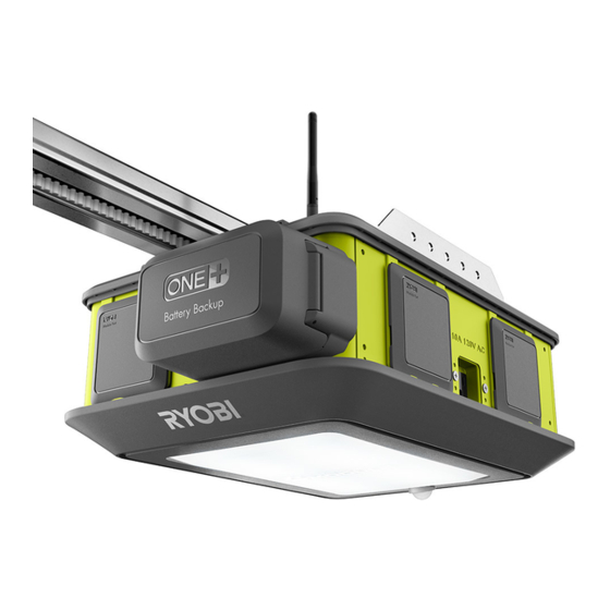
GARAGE DOOR OPENER
OUVRE-PORTE DE GARAGE
SISTEMA DE APERTURA PARA
PORTÓN DE GARAJE
GD200
Your garage door opener has been engineered and manufactured to our high standard for dependability, ease of operation,
and operator safety. When properly cared for, it will give you years of rugged, trouble-free performance.
WARNING:
before using this product.
Thank you for your purchase.
SAVE THIS MANUAL FOR FUTURE REFERENCE
Ce ouvre-porte de garage a été conçu et fabriqué conformément
à nos strictes normes de fiabilité, simplicité d'emploi et sécurité
d'utilisation. Correctement entretenu, cet outil vous donnera des
années de fonctionnement robuste et sans problème.
AVERTISSEMENT :
Pour réduire les risques de blessures, l'utilisateur doit lire et
veiller à bien comprendre le manuel d'utilisation avant d'employer
ce produit.
Merci de votre achat.
CONSERVER CE MANUEL POUR
FUTURE RÉFÉRENCE
To reduce the risk of injury, the user must read and understand the operator's manual
HomeLink
and the HomeLink
®
of Gentex Corporation.
HomeLink
et l'image de maison HomeLink
®
de Gentex Corporation.
HomeLink
y el icono de la casa de HomeLink
®
registradas de Gentex Corporation.
Su sistema de apertura para portón de garaje ha sido diseñado
y fabricado de conformidad con nuestras estrictas normas para
brindar fiabilidad, facilidad de uso y seguridad para el operador.
Con el debido cuidado, le brindará muchos años de sólido
funcionamiento y sin problemas.
ADVERTENCIA:
Para reducir el riesgo de lesiones, el usuario debe leer y
comprender el manual del operador antes de usar este producto.
Le agradecemos su compra.
GUARDE ESTE MANUAL PARA
FUTURAS CONSULTAS
house icon are registered trademarks
®
sont des marques déposées
®
son marcas comerciales
®
Advertisement
Table of Contents
Troubleshooting

Related Manuals for Ryobi GD200


Summary of Contents for Ryobi GD200
- Page 1 PORTÓN DE GARAJE HomeLink et l’image de maison HomeLink sont des marques déposées ® ® de Gentex Corporation. GD200 HomeLink y el icono de la casa de HomeLink son marcas comerciales ® ® registradas de Gentex Corporation. Your garage door opener has been engineered and manufactured to our high standard for dependability, ease of operation, and operator safety.
-
Page 2: Table Of Contents
TABLE OF CONTENTS TABLE DES MATIÈRES / ÍNDICE DE CONTENIDO Introduction ..................................2 Introduction / Introducción Specific Safety Rules ................................ 3 Règles de sécurité particulières / Reglas de seguridad específicas Safety Rules for Battery Operation ........................... 4 Règles particulières concernant l’utilisation de la pile / Reglas específicas para el funcionamiento a batería ... -
Page 3: Specific Safety Rules
Keep power Devices or features, such as the RYOBI Garage Door supply cord and wires away from pinch points and moving Opener Module System App, that allow you to open and parts. -
Page 4: Safety Rules For Battery Operation
SPECIFIC RULES FOR BATTERY OPERATION When battery pack is not in use, keep it away from explosion. Properly dispose of a dropped or damaged other metal objects like: paper clips, coins, keys, nails, battery immediately. screws, or other small metal objects that can make a Exercise care in handling batteries in order not to short the connection from one terminal to another. -
Page 5: Safety Rules For Charger
1. SAVE THESE INSTRUCTIONS - DANGER: TO REDUCE RISK OF FIRE OR ELECTRIC SHOCK CAREFULLY FOLLOW THESE INSTRUCTIONS. This manual contains important safety and operating instructions for the GD200 garage door opener. Before using garage door opener, read all instructions and cautionary markings on garage door opener, battery, and product using battery. -
Page 6: Symbols
SYMBOLS The following signal words and meanings are intended to explain the levels of risk associated with this product. SYMBOL SIGNAL MEANING Indicates an imminently hazardous situation, which, if not avoided, will result DANGER: in death or serious injury. Indicates a potentially hazardous situation, which, if not avoided, could result WARNING: in death or serious injury. -
Page 7: Symbols
SYMBOLS Some of the following symbols may be used on this product. Please study them and learn their meaning. Proper in- terpretation of these symbols will allow you to operate the product better and safer. SYMBOL NAME DESIGNATION/EXPLANATION Direct Current Type or a characteristic of current Alternating Current Type of current... -
Page 8: Electrical
ELECTRICAL ELECTRICAL CONNECTION GFCI receptacles do not protect against short circuits, overloads, or shocks. This product has a precision-built electric motor. It should The GFCI receptacles can be tested with the TEST and be connected to a power supply that is 120 volts, AC only RESET buttons. -
Page 9: Features
Input ........120V AC, 60 Hz. or 18V DC assembly. Motor ..............2 HPS** ** Horsepower Similar (HPs) designates that this system meets RYOBI pulling force specification for a 2.0 horsepower garage door opener. No Load Speed (Max) ......8.5 in. per second... - Page 10 FEATURES Wi-Fi Wire Wire Terminal Antenna Terminal Module (Keypad) (Sensor) Port #2 Module Port #7 Battery Receptacle Module Door Port #1 Rail Assembly Brackets Module Port #3 Module Port #6 Console Module Door Module Receptacle Port #4 Port #5 Fig. 4 10 - English...
- Page 11 FEATURES Module Module Port Cover Port #6 Module Port #7 Module Port #5 Battery Port Battery Door Console Door Light Motion Cover Sensor Car Remote (2) Outdoor Keypad Indoor Keypad Safety Sensor (2) Fig. 5 11 - English...
-
Page 12: Features
Passive infrared motion sensing turns the LED lights on when When not connected to an AC power source, the garage movement is detected in the garage. door opener and LED lights can be operated with RYOBI NOTE: The motion sensor is deactivated for ten seconds 18 Volt ONE+ lithium-ion batteries. -
Page 13: Loose Parts
LOOSE PARTS Child can become trapped or pinned under an automatic garage door resulting in serious injury or death. • Do not allow children to walk or run under a closing door. • Do not allow children to operate door opener controls. •... -
Page 14: Loose Parts
LOOSE PARTS The following items are included with your garage door opener: Header Bracket ..............................1 Wing Nut ................................2 Mounting Strap ..............................2 Door Bracket ................................. 1 Curved Door Arm ..............................1 Straight Door Arm ..............................1 Emergency Release Rope ............................ 1 Large Clevis Pin .............................. -
Page 15: Tools Needed
TOOLS NEEDED The following tools (not included or drawn to scale) are needed for assembly and adjustments: Level Flat Head 3/16 in. Screwdriver Drill Bit Rubber Mallet Hammer Adjustable Phillips Head Socket Bit (10, Pencil Wrench Screwdriver 11, and 13 mm) Socket Wrench Hacksaw Wire... -
Page 16: Assembly
ASSEMBLY Insert the edge of the end rail into the sleeve. Slide WARNING: together until rail clicks in place. If you cannot get the rail to fit by hand, try gently tapping it with a rubber mallet until it is snug and clicks into place. Be careful not to Always wear eye protection with side shields marked pinch or damage the belt. - Page 17 ASSEMBLY Move the front pulley toward the middle of the front rail. Pull the front pulley forward and slide the rod through the hole in the brace. Insert the edge of the front brace into the front rail. Slide together until brace clicks in place.
- Page 18 ASSEMBLY ADJUSTING THE BELT TENSION ATTACHING RAIL ASSEMBLY TO POWER See Figures 18 - 21. HEAD Using a 13 mm socket, turn the tension nut clockwise See Figures 22 - 25. to tighten the belt and counter-clockwise to loosen it. Locate the following items: Adjust the nut until there is approximately 3/8 to 1/2 in.
- Page 19 ASSEMBLY Hold the rail assembly above the power head with arrow pointing toward the front of the power head and the Front of garage door. Power Head Rotate the rail assembly until the opening in the rail is aligned with the sprocket.
-
Page 20: Installation
INSTALLATION IMPORTANT WARNING: INSTALLATION To reduce the risk of injury to persons – Only enable the RYOBI Garage Door Opener Module System App feature INSTRUCTIONS when installed with a sectional door. WARNING: WARNING: Do not connect to power supply until installation is TO REDUCE THE RISK complete. - Page 21 INSTALLATION CHECK THE CONDITION OF THE DOOR AND IDENTIFY THE SPRING TYPE Half-Open See Figure 26 - 28. Position WARNING: If the garage door does not move smoothly, binds, or is out of balance, have it repaired or replaced by a qualified Sectional service person.
- Page 22 INSTALLATION INSTALLING THE HEADER BRACKET 2 x 4 board. The 2 x 4 board can be installed between two studs or into masonry using lag screws and concrete anchors See Figures 29 - 31. (not supplied). Locate the following items: WARNING: Header Bracket Lag Screw (M8 x 2 in.) [4]...
- Page 23 INSTALLATION Stand on a ladder near the garage door as someone Draw a bisecting horizontal line above the high point: slowly raises it. While it’s moving, find and mark the • For sectional or single-panel garage doors with highest point of travel along the center line.
- Page 24 INSTALLATION Angle the rail assembly so that it rests against the header ATTACHING RAIL ASSEMBLY TO HEADER bracket. BRACKET NOTE: If a door spring or other obstruction is in the way, See Figure 32. have someone hold the garage door opener or help to Locate the following items: balance it on a raised support while you position the rail Large Clevis Pin...
- Page 25 INSTALLATION MOUNTING THE POWER HEAD TO THE Lower the garage door completely. CEILING Measure the space between the header bracket and the ceiling. See Figures 33 - 38. NOTE: For unfinished ceilings, measure the space between the header bracket and the nearest joists on WARNING: either side.
- Page 26 INSTALLATION To mount the power head to finished ceilings: Connect straps to garage door opener and to the joists using bolts, washers, and nuts (see figure 38). Tighten Install center bracket or brackets (not supplied) to the bolts and nuts with a 10 mm socket. nearest joists or other structural supports in garage ceiling using lag screws (not supplied).
- Page 27 INSTALLATION ATTACHING THE EMERGENCY RELEASE INSTALLING THE DOOR BRACKET ROPE See Figures 40 - 43. See Figures 39. Locate the following items: Door Bracket WARNING: Self-tapping Screws (2) Do not engage the emergency release while the garage NOTICE: door is open, do not use the emergency release rope to raise or lower the garage door, and only engage the Before installing the door bracket, ensure that your door emergency release when the door way is clear of all...
- Page 28 INSTALLATION NOTE: For wooden doors, drill hole completely through To install the bracket on single-panel doors: the door and install bracket using bolts (not provided) Lower the garage door completely. and nuts (not provided), see figure 41. Using a pencil and a level, draw a vertical line in the center of the top portion of the garage door.
- Page 29 INSTALLATION CONNECTING DOOR BRACKET TO OUTER To connect sectional doors: TROLLEY Lower the garage door completely. See Figures 44 - 49. Pull the emergency release rope down and slide outer trolley toward the garage door. Locate the following items: Secure straight door arm to the rear of the outer trolley Curved Door Arm using medium clevis pin and hitch pin.
- Page 30 INSTALLATION To connect single-panel doors: WARNING: Lower the garage door completely. Pull the emergency release rope down and slide outer DO NOT operate the garage door opener unless the trolley toward the garage door. safety sensors are installed and working correctly. Failure Place the curved and straight arms together and align to properly install and ensure that the safety sensors are the holes.
- Page 31 INSTALLATION NOTE: The top of the sensor should be between four and WARNING: six inches above the floor. NOTE: The receiving sensor has a green LED. Ensure that Connect the sensors using low voltage wires only to the lens on this sensor is not exposed to direct sunlight. prevent the risk of electric shock or serious personal Mark the position of the hole in the bracket.
- Page 32 INSTALLATION Twist the white wires from both sensors together and WARNING: insert them into the left terminal marked with W. For alignment instructions, see Aligning The Safety Make sure the keypad is mounted high enough to prevent Sensors in the Operations section. unauthorized activation of the garage door opener.
- Page 33 INSTALLATION Insert a flat head screwdriver into the tabs on the indoor Insert the white wire into the right terminal marked with W. keypad and remove the back cover. Hold the back cover against the wall. Use a pencil and a WARNING: level to mark screw hole placement.
-
Page 34: Installation
INSTALLATION INSTALLING THE OUTDOOR KEYPAD See Figures 61 - 63. Outdoor Locate the following items: Pencil Keypad Outdoor Keypad Screws (1.5 in., Phillips Hd.) [2] WARNING: Do not use garage door opener if keypads or remotes do not start and stop the motor. An opener that cannot Hole be controlled with a keypad or remote is dangerous, Screwdriver... -
Page 35: Operation
8. This operator system is equipped with an unattended NOTICE: operation feature. The door could move unexpectedly. NO ONE SHOULD CROSS THE PATH OF THE This product is designed to be powered by either a RYOBI MOVING DOOR. ONE+ 18V lithium-ion (Li-ion) battery pack (DC mode) ™... - Page 36 OPERATION CONNECTING THE GARAGE DOOR OPENER Connect the garage door opener to an AC power supply. TO A POWER SUPPLY Install battery pack into the garage door opener as described earlier. See Figures 64 and 65. Press on the battery pack to be sure contacts on the For AC power: battery pack engage properly with contacts in the garage Assemble and mount the garage door opener as...
- Page 37 OPERATION INSTALLING MODULES NOTE: If the garage door opener is unplugged and a charged battery pack is installed, the AC receptacles and module See Figures 66 and 67. ports will be disabled but the sensors and LED lights will The garage door opener can power a variety of AC and continue to function normally.
- Page 38 OPERATION ALIGNING THE SAFETY SENSORS Install and wire the safety sensors as described earlier in the Installation section. See Figure 68. Connect the garage door opener to an AC power supply. NOTE: Make sure the power supply is normal household WARNING: voltage, 120 volts, AC only, 60 Hz If wired correctly, the LED lights on both sensors should...
- Page 39 OPERATION SAFETY SENSOR DIAGNOSTIC FEEDBACK LED FUNCTIONS RED LED GREEN LED PROBLEM SOLUTION (TRANSMITTER) (RECEIVER) No problem indicated No action required Power head is unplugged or the battery Connect to power supply or charge is depleted the battery pack Wires from power head may be Replace damaged or broken wires damaged Wires not connected...
- Page 40 OPERATION SETTING THE DOOR TRAVEL LIMITS See Figures 69 - 76. DANGER: Ensure that the safety sensors are installed and working properly. Without the proper safety devices in place, a closing garage door could kill or seriously injure someone in its path. Fully Closed Position The console on your garage door opener makes it easy to...
- Page 41 OPERATION NOTICE: Do not open or close the garage door using the indoor keypad or remotes until the travel limits have been properly set. Doing so could cause severe damage to the garage door or the garage door opener. Correct (Fully Open Position) Before setting the travel limit: Pull the emergency release rope down and manually open...
- Page 42 OPERATION To set the travel limit for the closed position: Press and hold the DOWN button for three seconds. After you release the button, it will begin blinking and continue blinking until the travel limit has been set. Down Press and hold the DOWN button to move the garage door to the closed position.
- Page 43 OPERATION USING THE INDOOR KEYPAD can only be controlled using the indoor keypad and smart phone. The unit will not respond to car remotes or the See Figure 77. outdoor keypad. NOTE: The LEDs in the indoor keypad will blink when the WARNING: unit is in vacation mode.
- Page 44 OPERATION TESTING THE AUTOMATIC REVERSAL Press and release the UP/DOWN button on the indoor keypad to raise the garage door. SYSTEM Place a 1-1/2 in. board (approx. the size of a 2x4 laid flat) See Figure 78. on the garage floor beneath the door. Press and release the UP/DOWN button on the indoor DANGER: keypad to lower the garage door.
- Page 45 OPERATION PROGRAMMING THE OUTDOOR KEYPAD See Figures 79 - 80. WARNING: Program Keep moving door in sight when using outdoor keypad. Contact with moving door can cause DEATH or serious injury. Once you begin programming the outdoor keypad, you have two minutes to complete each step.
-
Page 46: Operation
Wi-Fi signal is lost or not properly functioning. WARNING: Download the RYOBI Garage Door Opener Module Sys- Devices or features, such as the RYOBI Garage Door tem App from the App Store or Google Play Store. -
Page 47: Maintenance
MAINTENANCE IMPORTANT SAFETY WARNING: INSTRUCTIONS Before inspecting, cleaning or servicing the machine, lower the garage door, shut off motor, wait for all moving parts to stop, disconnect unit from power supply, and WARNING: remove all modules. Failure to follow these instructions can result in serious personal injury or property damage. -
Page 48: Maintenance
MAINTENANCE REPLACING CAR REMOTE BATTERIES Snap the sections together to close. See Figure 83. Make sure the remote is securely reassembled before attaching the visor clip. WARNING: KEEP OUT OF REACH OF CHILDREN. Swallowing Coin batteries may lead to serious injury or death. Visor WARNING: Clip... -
Page 49: Accessories
ACCESSORIES The following accessories are not included with your garage door opener but may be available where you purchased this product. For assistance call 1-877-205-5714. 8 ft. Extension Kit .............................GDAEXT100 Bluetooth Speaker ..............................GDM120 Dual Laser Park Assist ............................GDM222 ... -
Page 50: Troubleshooting
TROUBLESHOOTING PROBLEM POSSIBLE CAUSE SOLUTION All of the console buttons are DC voltage below 24V. Disconnect the unit from the power supply. blinking continuously Wait several minutes before reconnecting. If problem persists, contact customer service. DC voltage exceeds 40 volts Disconnect the unit from the power supply. -
Page 51: Troubleshooting
TROUBLESHOOTING PROBLEM POSSIBLE CAUSE SOLUTION Garage door opener is in the fully The safety sensors are not Inspect sensor wires for damage and open position and cannot be receiving power. ensure they are installed correctly. Reset closed with a car remote, smart travel limits. -
Page 52: Warranty
PROPERTY, LOSS OF REVENUE, LOSS OF USE OF THE of purchase will be required to substantiate any warranty PRODUCT, LOSS OF TIME, OR INCONVENIENCE, SOME claim. All warranty work must be performed by a RYOBI ™ STATES DO NOT ALLOW THE EXCLUSION OR LIMITATION Authorized Service Center. - Page 53 FCC COMPLIANCE The following FCC compliance information is for the GD200 garage door opener only. For information regarding other products, like modules and accessories, refer to the labels and documentation included with those items. WARNING: Changes or modifications to this unit not expressly approved by the party responsible for compliance could void the user’s authority to operate the equipment.
- Page 54 Please obtain your model and serial number from the product data plate. MODEL NUMBER _______________ SERIAL NUMBER ____________________________ RYOBI is a registered trademark of Ryobi Limited and is used pursuant to a license granted by Ryobi Limited. Pour faire une demande de réparations ou obtenir des pièces de rechange, trouver un Centre de réparations agréé...