Table of Contents
Advertisement
Quick Links
Advertisement
Table of Contents

Related Manuals for Pfaff 294


Summary of Contents for Pfaff 294
- Page 1 1293 Instruction Manual 1294 296-12-18 170 Betriebsanleitung engl. 03.99...
- Page 2 This Instruction Manual is valid for all models and subclasses listed in the chapter "Specifications". The reprinting, copying or translation of PFAFF Instruction Manuals, whether in whole or in part, is only permitted with our previous authorisation and with written reference to the source.
-
Page 3: Table Of Contents
Proper use ......................... 2 - 1 Specifications ......................3 - 1 PFAFF 1293 ........................ 3 - 1 PFAFF 294 / PFAFF 1294 .................... 3 - 2 Models and subclasses ....................3 - 3 Machine disposal ..................... 4 - 1 Transportation, packing and storage ..............5 - 1 Transportation to customer’s premises .............. -
Page 4: Contents
Removing /inserting the bobbin case ................9 - 4 Threading the bobbin case / adjusting the thread tension ..........9 - 4 Threading the needle thread / adjusting the needle thread tension (PFAFF 1293) ..9 - 5 Threading the needle thread / adjusting the needle thread tension (PFAFF 294 and PFAFF 1294) .................. - Page 5 .04.16 Thread check spring (PFAFF 1293 and on machines without -900/56) ....11 - 18 .04.17 Thread check spring (on PFAFF 294 and PFAFF 1294 with - 900/56) ...... 11 - 19 .04.18 Bobbin winder ......................11 - 20 .04.19 Adjusting the presser bar lifting lever with subclass -911/97 ........
-
Page 6: Safety
Safety Safety Regulations This machine is constructed in accordance with the European regulations indicated in the conformity and manufacturer's declarations. In addition to this instruction manual, please also observe all generally accepted, statutory and other legal requirements, including those of the user's country, and the applicable pollution control regulations! The valid regulations of the regional social insurance society for occupational accidents or other supervisory authorities are to be strictly adhered to! -
Page 7: Safety Symbols
The user must ensure that none of the safety devices are removed nor put out of working order. The user must ensure that only authorized persons operate and work on the machine. For further information please refer to your PFAFF agency. 1 - 2... -
Page 8: Operating And Technical Staff
Safety Notes for operating and technical staff Operating staff .05.01 Operating staff are the persons responsible for setting up, operating and cleaning the mach-ine and for removing any disturbances in the sewing area. The operating staff are obliged to observe the following points, and must: always observe the notes on safety in this instruction manual! avoid using any working methods which adversely effect the safety of the machine! avoid wearing loose-fitting clothing or jewelry such as necklaces or rings! -
Page 9: Danger Warnings
Safety Danger warnings A working area of 1 metre is to be kept free both in front of and behind the machine while it is in operation, so that it is always easily accessible. Never reach into the sewing area while sewing! Danger of injury by the needle! Never leave objects on the table while adjusting the machine settings! Objects can become trapped or be hurled out! Danger of injury! -
Page 10: Proper Use
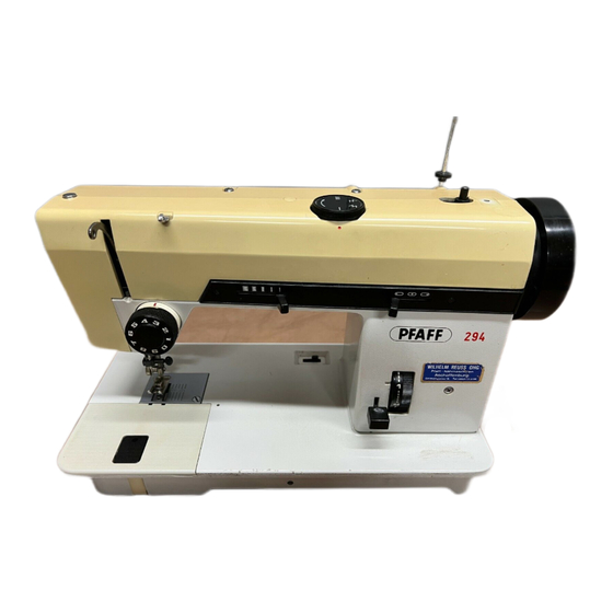
Proper use Proper use The PFAFF 294 is a two-needle lockstitch post-bed sewing machine with roller presser, bottom feed dog and vertical sewing hook. The PFAFF 1293 is a single-needle lockstitch post-bed sewing machine with roller presser, bottom feed dog and large vertical sewing hook. -
Page 11: Specifications
Specifications Specifications PFAFF 1293 Stitch type: ....................301 (lockstitch) Needle system: ......................134 Needle thickness in 1/100 mm: Model C: ........................ 110 - 140 Model C/D and D: ....................160 - 190 Max. thread size (synthetic ): Model C: ........................11/3 Model C/D: ........................ -
Page 12: Pfaff 294 / Pfaff 1294
Specifications PFAFF 294 / PFAFF 1294 Stitch type: ....................301 (lockstitch) Needle system: ......................134 Needle thickness in 1/100 mm: Model B: ........................80 - 100 Model C: ........................ 110 - 140 Model C/D and D: ....................160 - 190 Max. -
Page 13: Models And Subclasses
Specifications Models and subclasses Model B (PFAFF 294): ............For medium-weight materials Model C: .................. For medium-heavy materials Model C/D ................For medium-heavy materials Model D: ....................For heavy materials Additional equipment: Subclass -750/04 ................... Roller presser drive Subclass -900/56 ..................Thread trimmer Subclass -910/01 ................. -
Page 14: Disposal Of Machine
Disposal of Machine Disposal of Machine Proper disposal of the machine is the responsibility of the customer. The materials used for the machine are steel, aluminium, brass and various plastic mat- erials. The electrical equipment comprises plastic materials and copper. The machine is to be disposed of according to the locally valid pollution control regula- tions;... -
Page 15: Transportation, Packing And Storage
Transportation, packing and storage Transportation, packing and storage Transportation to customer's premises Within the Federal Republic of Germany, complete machines (with table and motor) are delivered without packing. Machines without table (only sewing heads) and machines intended for exports are packed. Transportation inside the customer's premises The manufacturer cannot be made liable for transportation inside the customer's premises nor to other operating locations. -
Page 16: Explanation Of Symbols
Explanation of symbols Explanation of symbols In this instruction manual, work to be carried out or important information is accentuated by symbols. These symbols have the following meanings: Note, information Cleaning, care Lubrication Maintenance, repairs, adjustment, service work (only to be carried out by technical staff) 6 - 1... -
Page 17: Controls
Controls Controls On/off switch Turn the machine on and off by turning the on/off switch 1. The switch in the illustration is fitted to machines with Quick motors. When other motors are used, other switches may be fitted. Fig. 7 - 01 Pedal (on machines without automatic backtacking mechanism and presser foot lift -911/97) -
Page 18: Pedal (On Machines With Automatic Backtacking Mechanism And Presser Foot Lift -911/97)
Controls Pedal (on machines with automatic backtacking mechanism and presser foot lift -911/97) = Neutral position +1 = Sew -1 = Lift roller presser -2 = Trim thread (on machines with thread trimmer -900/56) For other pedal functions see the motor instruction manual. -
Page 19: Knee Lever (On Machines Without Automatic Backtacking Mechanism And Presser Foot Lift -911/97)
Controls Knee lever (on machines without automatic backtacking mechanism and pressser foot lift -911/97) The roller presser is raised by operating the knee lever 1. Fig. 7 - 05 Key on the machine head (for machines with automatic backtacking mechanism and presser foot lift -911/97) Switch to reverse sewing by pressing key 1 while sewing. -
Page 20: Lever For Lifting The Roller Presser
Controls Lever for lifting the roller presser The roller presser is lifted by raising lever 1. Fig. 7-07 shows a PFAFF 1294. Fig. 7 - 07 Feed regulator and reverse sewing lever Adjust the stitch length by turning the knurled nut on lever 1. -
Page 21: Feed Regulator (On Machines With Automatic Backtacking Mechanism And Presser Foot Lift -911/97)
Controls Feed regulator (on machines with automatic backtacking mechanism and presser foot lift -911/97) The forward stitch length is set by turning the knurled screw 1. The reverse stitch length is set by turning the knurled screw 2. You can set the length of the reverse stitch as long as required, independent of the foward stitch. -
Page 22: Installation And Commissioning
Installation and commissioning Installation and commissioning The machine must only be installed and commissioned by qualified personnel! All relevant safety regulations are to be observed! If the machine is delivered without a table, it must be ensured that the stand and the table top which you intend to use can hold the weight of the machine. -
Page 23: Adjusting The V-Belt Tension
Installation and commissioning Adjusting the V-belt tension .01.02 Loosen nuts 1. Tighten the V-belt with belt take-up bracket 2. Tighten nuts 2. Fig. 8-02 shows a Quick motor. If another motor is used, proceed as described in the motor’s instruction manual. Fig. -
Page 24: Fitting The Lower V-Belt Guard
Installation and commissioning Fitting the lower V-belt guard .01.04 Align belt guard 1 in such a way that both the motor pulley and the V-belt run freely. Fig. 8-04 shows a Quick motor. If another motor is used, proceed as described in the motor’s instruction manual. -
Page 25: Fitting The Reel Stand
Installation and commissioning Fitting the reel stand .01.06 Fit the reel stand as shown in Fig. 8-06. Insert reel stand in the table-top hole and fasten it with the included nuts. Fig. 8 - 06 Commissioning Check the machine, in particular the electrical leads and pneumatic connection tubes, for any damage. -
Page 26: Setting Up
Before all setting up work, the machine is to be switched off at the on/off switch or disconnected from the electricity supply by removing the plug from the mains! Inserting the needle in the PFAFF 1293 Turn the machine off! Danger of injury if the machine is started accidentally! Use only system 134 needles. -
Page 27: Inserting The Needle In The Pfaff 294 And Pfaff 1294
Setting up Inserting the needle in the PFAFF 294 and PFAFF 1294 Turn the machine off! Danger of injury if the machine is started accidentally! Use only system 134 needles. Raise the roller presser and swing it out. Raise the needle bar as far as possible and loosen screws 1. -
Page 28: Winding The Bobbin Thread, Adjusting The Thread Tension
Setting up Winding the bobbin thread, adjusting the thread tension Fig. 9 - 03 Place an empty bobbin 1 onto bobbin spindle 2. Thread the bobbin in accordance with Fig. 9-03 and wind it clockwise around the bobbin 1 a few times. Engage the bobbin winder by pressing bobbin spindle 2 and lever 3 at the same time. -
Page 29: Removing /Inserting The Bobbin Case
Setting up Removing /inserting the bobbin case Turn the machine off! Danger of injury if the machine is started accidentally! Removing the bobbin case: Raise take-up lever as far as possible. Open the post cover, raise latch 1 and remove bobbin case 2. Inserting the bobbin case: Insert bobbin case 2 so that it clicks into place. -
Page 30: Threading The Needle Thread / Adjusting The Needle Thread Tension (Pfaff 1293)
Setting up Threading the needle thread / adjusting the needle thread tension (PFAFF 1293) Fig. 9 - 06 Turn the machine off! Danger of injury if the machine is started accidentally! Thread the needle thread as shown in Fig. 9-06. Take care that the needle is threaded from the left. -
Page 31: Threading The Needle Thread / Adjusting The Needle Thread Tension (Pfaff 294 And Pfaff 1294)
Adjust the needle thread tension by turning the knurled screw 1 (right needle) or 2 (left needle). The illustration shows the PFAFF 1294 with thread trimmer -900/56. 9 - 6... -
Page 32: Care And Maintenance
Care and maintenance Care and maintenance Servicing and maintenance intervals Clean the hook compartment ...... daily, several times if in continuous operation Check the air pressure ................daily, before use Clean the water container of the air filter/regulator ........daily, before use Lubricate the hook .................. -
Page 34: Lubricating The Hook
Only use oil with a mean viscosity of 22.0 mm²/s at 40° C and a density of 0.865 g/cm at 15° C! We recommend PFAFF sewing machine oil, Fig. 10 - 03 part No. 280-1-120 144. Lubricating the needle-head parts... -
Page 35: Checking / Adjusting The Air Pressure
Care and maintenance Checking and adjusting the air pressure Before each use of the machine, check the air pressure on gauge 1. The gauge 1 must display a pressure of 6 bar. If necessary, alter the pressure to this level. To do so, lift knob 2 and turn it until the required pressure is reached. -
Page 36: Adjustment
Adjustment Justierung The illustrations in this section show the two-needle machines. For the PFAFF 1293 single-needle machine, various adjustments only have to be made on one side, i.e. in the right hook compartment. Notes on adjusting All adjustments in these adjustment instructions are based on a completely installed machine and must only be carried out by appropriately trained mechanics. -
Page 37: Adjusting The Basic Machine
Adjustment Adjusting the basic machine Positioning the feed dog .04.01 Requirement 1. The feed dog must be the same distance from the left and the right side of the needle- plate cutout. 2. When the longest stitch length is set, the feed dog must be the same distance from the needle plate cutout at its front and rear point of reversal. -
Page 38: Height Of The Feed Dog
Adjustment Height of the feed dog .04.02 Requirement With the stitch length set at „0“, the bottom feed dog must protrude over the needle plate by the height of its teeth when at its top point of reversal. Fig. 11 - 02 Set stitch length „0“. -
Page 39: Pre-Adjusting The Needle Height
Adjustment Pre-adjusting the needle height .04.03 Requirement With the needle bar at BDC, the distance between the needle bar and the needle plate must be 14 mm. Fig. 11 - 03 Position needle bar 1 (screw 2) in accordance with the requirement, without twisting it. 11 - 4... -
Page 40: Centering The Needle In The Needle Hole
Adjustment Centering the needle in the needle hole .04.04 Requirement With the stitch length set at „0“, the needle must enter the needle hole exactly in the middle. Fig. 11 - 04 Loosen screws 1, 2 and 3. Position the needle directly above the feed dog by turning the balance wheel. Position needle bar frame 4 in accordance with the requirement. -
Page 41: Driving Motion Of The Feed Dog
Adjustment Driving motion of the feed dog .04.05 Requirement With the longest stitch set and the needle positioned 3 mm after BDC, the feed dog should not move when the reverse-feed lever is operated. Fig. 11 - 05 Set the longest stitch. Loosen screws 1 far enough so that the eccentric 2 can only be turned on the shaft with difficulty. -
Page 42: Lifting Motion Of The Feed Dog
Adjustment Lifting motion of the feed dog .04.06 Requirement 1. With the needle set at its TDC, the feed dog must be at its top point of reversal. 2. With the longest stitch set, the teeth of the feed dog must be at the same height as the surface of the needle plate, when the needle point enters the needle hole. -
Page 43: Basic Position Of The Roller Presser Drive (Only On Machines With Subcl. -4/01)
Adjustment Basic position of the roller presser drive .04.07 (only on machines with subcl. -4/01) Requirement 1. With the longest stitch setting the clamping surfaces of lever 1 must be horizontal, when these are at their front point of reversal. 2. -
Page 44: Synchronizing The Roller Presser And Feed Dog
Adjustment Synchronizing the roller presser and feed dog .04.08 (only on machines with subcl. -4/01) Requirement The feed strokes of the roller presser and the feed dog must be equal. Fig. 11 - 08 Adjust lever 1 (screw 2) in accordance with the requirement. 11 - 9... -
Page 45: Releasing The Roller Presser For Reverse Sewing (Only On Machines With Subcl. -4/01)
Adjustment Releasing the roller presser for reverse sewing .04.09 (only on machines with subcl. -4/01) Requirement 1. For reverse sewing, the roller presser must be released (cylinder 8 extended). 2. When the roller presser and feed dog are lowered, the clearance between tension pin 6 and bearing 7 should be 0.5 mm, if cylinder 8 has not been extended. -
Page 46: Hook-To-Needle Clearance, Needle Rise, Needle Height And Needle Guard
Adjustment Hook-to-needle clearance, needle rise, needle height and needle guard .04.10 Requirement In the needle rise position (see table), the following applies: 1. The hook point must be at the “needle centre“ position and clear the needle by 0.05 - 0.1 mm. - Page 47 Adjustment Remove the feeler gauge and turn the balance wheel in its direction of rotation until the adjustable clamp is touching the needle bar bearing. Position posts 5 in accordance with requirement 1. Tighten screws 1 and 4. Position the hook point at the needle centre, taking care to ensure that the needle is not deflected by needle guard 8.
-
Page 48: Bobbin-Case Opener
Adjustment Bobbin-case opener .04.11 Requirement The needle thread must not be clamped between the bobbin-case opener 2 and the bobbin- case base 4, nor must it be clamped between projection 5 and the retaining trip of the needle plate (see arrows). Fig. -
Page 49: Safety Coupling
Adjustment Safety coupling .04.12 The safety coupling 4 is set by the manufacturer. If the thread jams, the safety coupling 4 disengages to prevent damage to the hook. A description of how to re-engage it follows. Fig. 11 - 12 Remove the jammed thread. -
Page 50: Clearance Between Roller Presser And Needle Plate
Adjustment Clearance between roller presser and needle plate .04.13 Requirement The clearance between the raised roller presser and the needle plate must be 5 mm..Fig. 11 - 13 Raise roller presser with the presser bar lifter. Reduce the pressure on the roller pressure (screw 1). -
Page 51: Pressure Of Roller Presser
Adjustment Pressure of roller presser .04.14 Requirement The material must be fed reliably even at top sewing speed. Fig. 11 - 14 Turn screw 1 in accordance with the requirement. On Model D machines the pressure can be increased additionally via screw 2. 11 - 16... -
Page 52: Needle Thread Tension Release
Adjustment Needle thread tension release .04.15 Requirement With the roller presser raised, the two tension discs 4 must be at least 0.5 mm apart. 0,5 mm Fig. 11 - 15 Align pressure plate 1 behind tension carrier plate 2 in accordance with the requirement..The clearance of 0.5 mm is a minimum and can increase to more than 1 mm when thick threads are used. -
Page 53: Thread Check Spring (Pfaff 1293 And On Machines Without -900/56)
Adjustment Thread check spring (PFAFF 1293 and on machines without -900/56) .04.16 Requirement The motion of the thread check spring 5 should have ceased when the needle point enters the material ( = approx. 7 mm spring stroke). Fig. 11 - 16 Turn retainer 1 (screw 2) in accordance with the requirement. -
Page 54: Thread Check Spring (On Pfaff 294 And Pfaff 1294 With -900/56)
Adjustment Thread check spring (on PFAFF 294 and PFAFF 1294 with -900/56) .04.17 Requirement The motion of the thread check springs 1 and 6 should have ceased when the needle points enter the material ( = approx. 7 mm spring stroke). -
Page 55: Bobbin Winder
Adjustment Bobbin winder .04.18 Requirement 1. When the bobbin winder is switched on, the friction wheel 5 must engage reliably. 2. When the bobbin winder is switched off, the friction wheel 5 must not touch the drive wheel 1. 3. The bobbin winder must switch off automatically when the thread level is approx. 1 mm from the edge of the bobbin. -
Page 56: Adjusting The Presser Bar Lifting Lever With Subclass -911/97
Adjustment Adjusting the presser bar lifting lever with subclass -911/97 .04.19 Requirement When the automatic presser foot lift is operated 1. the roller presser must rise 5 mm 5 mm 5 mm 5 mm 5 mm above the needle plate and 2. -
Page 57: Adjusting The Presser Bar Lifting Lever Without Subclass -911/97
Adjustment Adjusting the presser bar lifting lever without subclass -911/97 .04.20 Requirement When the knee lever is operated 1. the roller presser must rise 5 mm above the needle plate and 2. the tension discs of the thread tension device must be 0.5 mm apart. Fig. -
Page 58: Adjusting The Thread Trimmer -900/56
Adjustment Adjusting the thread trimmer -900/56 Engaging solenoid .05.01 Requirement 1. Mounting bracket 1 must be in the middle of its adjusting range and parallel with the right-hand edge of the mounting bracket. 2. When the thread trimmer is in its resting position the core of solenoid 3 must protrude from the solenoid housing by about 4 mm. -
Page 59: Control Cam (Preliminary Adjustment)
Adjustment Control cam (preliminary adjustment) .05.02 Requirement 1. Control cam 1, must be centred with the cutout of bearing mounting 5. 2. With the needle bar at t.d.c., screws 2 must be visible from the front and aligined parallel with the bedplate. Fig. -
Page 60: Tripping Lever Spring Action
Adjustment Tripping lever spring action .05.03 Requirement When the thread trimmer is in its resting position, it must be possible to press control lever 3 about 1 mm towards the bedplate (spring action). Fig. 11 - 23 Turn screw 1 (nut 2) according to Requirement. 11 - 25... -
Page 61: Tripping Lever Stroke
Adjustment Tripping lever stroke .05.04 Requirement 1. When engaging lever 5 is operated the pin of control lever 6 must drop freely into the track of control cam 7. 2. After thread trimming, control lever 6 must pass freely on the right side of stop plate 3 and engage control lever 5 behind stop plate 3. -
Page 62: Thread Catcher Drive Linkage
.05.05 Requirement 1. On the PFAFF 294 and PFAFF 1294 thread-catcher drive linkage 1 must have a length of 128 mm, less half of the needle gauge. On the PFAFF 1293 thread catcher drive linkage 1 must have a length of 128 mm. - Page 63 Adjustment Linkage bar ( only on the PFAFF 294 and PFAFF 1294 ) .05.06 Requirement The length of linkage bar 1 must be the same as the distance between the two thread- catcher drive shafts 3. Fig. 11 - 26 Adjust middle section 1 (nuts 2) of the linkage bar according to Requirement.
-
Page 64: Thread-Catcher Height
Adjustment Thread catcher height .05.07 Requirement There must be a clearance of 0.7 mm between the underside of thread catcher 4 and bobbin case cap 5. Fig. 11 - 27 Loosen screws 1 and 2. Adjust the height of shaft 3 according to Requirement. Tighten screws 1. -
Page 65: Thread Catcher Resting Position
Adjustment Thread catcher resting position .05.08 Requirement When the thread trimmer is in its resting poistion there must be a clearance of about 4 mm between the point of catcher 3 and the cutting edge of knife 4. 4 mm Fig. -
Page 66: Knife Pressure
Adjustment Knife pressure .05.09 Requirement When the front edge of thread catcher 3 has passed the knife cutting edge by half, knife 1 must rest with light pressure on the edge of the catcher. Fig. 11 - 29 Adjust knife 1 (screws 2) according to Requirement 11 - 31... -
Page 67: Bobbin-Thread Trapping Spring
Adjustment Bobbin thread trapping spring .05.10 Requirement 1. Bobbin thread trapping spring 3 must not be deflected by thread catcher 4 in any phase. 2. After the trimming action the bobbin thread must be securely trapped. 3. It must be possible to insert and remove the bobbin from the hook without any hindrance. Fig. -
Page 68: Control Cam (Final Adjustment)
Adjustment Control cam (final adjustment) .05.11 Requirement The trimming action must be just completed when the take-up lever is at t.d.c. Fig. 11 - 31 Turn control cam 1 (screws 2) according to Requirement. 11 - 33... -
Page 69: Release Lever
Adjustment Release lever .05.12 Requirement When the pin of control lever 3 has dropped into the track of control cam 4 and the needle bar is at b.d.c. there must be a clearance of about 1 mm between control lever 3 and release lever 5. -
Page 70: Release Rod
Adjustment Release rod .05.13 Requirement 1. When the roller presser is resting on the needle plate, pin 3 must rest at the lower end of the elongated hole in pull-rod 1. 2. The tension discs of the needle thread tension device must not be moved apart in this position. - Page 71 Adjustment Adjusting the synchroniser .05.14 Requirement 1. When sewing is interrupted, the machine must position at about 4 mm past b.d.c. of the needle bar. 2. After thread trimming the machine must position with the take-up lever at t.d.c. The maximum speed for the start backtack, finish backtack and intermediate backtack is 800 min Carry out adjustment as stipulared in the instruction manual of motor.
- Page 72 G.M. PFAFF Aktiengesellschaft Postfach 3020 D-67653 Kaiserslautern Königstr. 154 D-67655 Kaiserslautern Telefon: (0631) 200-0 Telefax: (0631) 172 02 Telex: 45753 PFAFF D Gedruckt in der BRD Printed in Germany Imprimé en R.F.A. Impreso en la R.F.A.