
Related Manuals for Yard Works 60-3753-6

Summary of Contents for Yard Works 60-3753-6
- Page 1 Models: 60-3753-6 60-3754-4 IMPORTANT: Read safety rules and instructions carefully before operating equipment. FOR CUSTOMER ASSISTANCE CALL 1-866-523-5218 Printed in U.S.A. 772C0713 (1/2005)
- Page 2 Content Customer Support Important Safe Operation Practices Setting Up Your SnowtThrower Knowing Your Snow Thrower Operation This Operator’s Manual is an important part of your new snow thrower. It will help you to assemble, prepare and maintain the unit for best performance. Please read and understand what it says. Before you start assembling your new snow thrower, please locate the model plate on the equipment and copy the information from it in the space provided below.
- Page 3 SECTION 1: IMPORTANT SAFE OPERATION PRACTICES WARNING: This symbol points out important safety instructions which, if not followed, could endanger the personal safety and/or property of yourself and others. Read and follow all instructions in this manual before attempting to operate this machine. Failure to comply with these instructions may result in personal injury. When you see this symbol—heed its warning.
- Page 4 Muffler and engine become hot and can cause a burn. Do not touch. Exercise extreme caution when operating on or crossing gravel surfaces. Stay alert for hidden hazards or traffic. Exercise caution when changing direction and while operating on slopes. 10.
- Page 5 SECTION 2: SETTING UP YOUR SNOW THROWER NOTE: The snow thrower is shipped with oil and WITHOUT GASOLINE. After assembly, refer to separate engine manual for proper fuel and engine oil recommendations. Unpacking • Cut along corners of the carton and lay it down flat. Remove packing material.
- Page 6 Chute Assembly (all models) 1. Apply a light lubricant (i.e. 3-in-1 oil) to the base of the chute assembly. 2. Place the chute assembly on the lip of the chute adapter. See Figure 3 3. One end of each chute keeper is already attached to the chute flange.
- Page 7 Figure 8 Lamp Wire (optional) 1. Make sure the lamp wire is wrapped down the right handle as shown in Figure 9 . 2. Make sure the lamp wire is plugged into the alternator lead wire under the fuel tank. See Figure 9 inset.
-
Page 8: Ignition Key
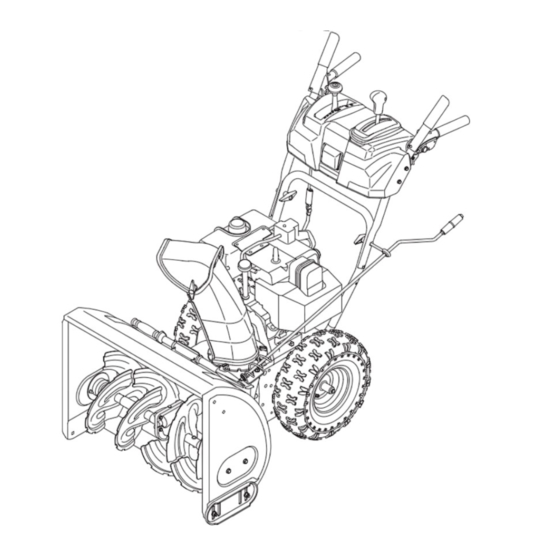
SECTION 3: KNOWING YOUR SNOW THROWER Drive Control Electric Starter Button Gas Cap Oil Fill Chute Assembly Clean-out Tool Shave Plate Augers WARNING: Read, understand, and follow all instructions and warnings on the machine and in this manual before operating. NOTE: For detailed starting instructions and more information on all engine controls, refer to the separate... -
Page 9: Auger Control
Auger Control The auger control is located on the left handle. Squeeze the auger control against the handle to engage the augers and start snow throwing action. Release to stop. Drive Control The drive control is located on the right handle. Squeeze the drive control against the handle to engage the wheel drive. -
Page 10: Chute Assembly
Electric Starter Outlet (If so equipped) Requires use of a three-prong outdoor extension cord (packed with the snow thrower) and a 120V power source/wall outlet. SECTION 4: OPERATING YOUR SNOW THROWER Before Starting WARNING: Read, understand, and follow all instructions and warnings on the machine and in this manual before operating. -
Page 11: Stopping The Engine
NOTE: If the engine is already warm, place choke control in the OFF position instead of FULL. • Push the primer two or three times for cold engine start, making sure to cover vent hole in the center of the primer when pushing. DO NOT use primer to restart a warm engine NOTE: after a short shutdown. -
Page 12: Operating Tips
Auger Control Test Perform the following test before IMPORTANT: operating your snow thrower for the first time and at the start of each winter season. Check the adjustment of the auger control as follows: • When the auger control is released and in the disengaged “up”... - Page 13 Chute Clean-Out Tool The chute clean-out tool is conveniently fastened to the rear of the auger housing with a mounting clip. Should snow and ice become lodged in the chute assembly during operation, proceed as follows to safely clean the chute assembly and chute opening: •...
-
Page 14: Shift Rod Adjustment
SECTION 5: MAKING ADJUSTMENTS WARNING: Never attempt to make any adjustments while the engine is running, except where specified in operator’s manual. Shift Rod Adjustment If the full range of speeds (forward and reverse) cannot be achieved, refer to the figures to the right and adjust the shift rod as follows: Place the shift lever in the fastest forward speed position. - Page 15 Figure 17 Drive Control When the drive control is released and in the disengaged “up” position, the cable should have very little slack. It should NOT be tight. Check the adjustment of the drive control as follows: 1. With the drive control disengaged, push the snow thrower gently forward.
-
Page 16: Shave Plate And Skid Shoes
SECTION 6: MAINTAINING AND SERVICING YOUR SNOW THROWER WARNING: Before lubricating, repairing, or inspecting, disengage all controls and stop engine. Wait until all moving parts have come to a complete stop. Engine Refer to the separate engine manual packed with your unit for all engine maintenance. -
Page 17: Replacing Belts
• To remove skid shoes, remove the four carriage bolts and hex flange nuts which secure them to the snow thrower. Reassemble new skid shoes with the four carriage bolts (two on each side) and hex flange nuts. Refer to Figures 19 and 21. •... - Page 18 • Push idler away from the chute and insert a Philips head screwdriver in the hole on the idler as shown in Figure 26. This will release tension on drive belt. Engine Pulley Drive Belt Idler Figure 26 • Pull drive belt out and away from the engine pulley to remove.
- Page 19 Figure 28 SECTION 7: OFF-SEASON STORAGE If unit is to be stored over 30 days, prepare for storage as instructed in the separate engine manual packed with your unit. WARNING: Never store snow thrower with fuel in tank indoors or in poorly ventilated areas, where fuel fumes may reach an open flame, spark or pilot light as on a furnace, water heater, clothes dryer or gas appliance.
-
Page 20: Troubleshooting
SECTION 8: TROUBLE SHOOTING Problem Engine fails to start. 1. Fuel tank empty, or stale fuel. 2. Blocked fuel line. 3. Choke not in ON position 4. Faulty spark plug. 5. Safety key not in ignition switch on engine. 6. Spark plug wire disconnected. 7. - Page 21 SECTION 9: YARDWORKS 4 YEAR LIMITED WARRANTY For FOUR YEARS from the date of retail purchase within Canada, YARDWORKS CANADA will, at its option, repair or replace, for the original purchaser, free or charge, any part or parts found to be defective in material or workmanship.
-
Page 22: Illustrated Parts List
AUGER HOUSING COM PO NENTS/COMPOSANTS DU LOGEMENT DES TARIÈRES SIZE AUGER AUGER AXLE/ TAILLE HOUSING/ ESSIEU DES LOGEMENT DES TARIÈRES TARIÈRES 684-04067 711-04286 684-04069 711-04285 684-04071 711-04284 684-04072 711-04284 684-04073 711-04283 684-04074 711-04283 684-04063 711-04282 684-04075 711-04282 Plain/Ordianire Serrated/Dentelée SHAVE PLATE GEARBOX ASS’Y/ LAME EN SEM BLE DE LA... - Page 23 PART N° DE N° DE RÉF PIÈCE 731-2643 Clean-Out Tool 684-04057 Im pel ler Ass'y 12 po 710-0347 Hex Screw 3/8-16 X 1.75 710-0451 Car riage Bolt 5/16-18 x .75 Gr. 1 710-0703 Car riage Screw 1/4-20 x .75 Gr. 5 710-0726 Hex Wash HD AB Tap Scr 5/16 X .75 712-04063...
- Page 25 PART N° DE N° DE RÉF PIÈCE DE SCRIP TION 656-0012A Friction Wheel Disc Assembly 684-04066 Friction Wheel Ass’y, Bearing 4.9 OD 684-04045 Friction Wheel Support Brkt Ass’y 710-0627 Hex L-Bolt 5/16-24 x .75 Gr. 5 710-1652 Hex Wash Hd TT Scr. 1/4-20 x .625 710-0788 Hex Bolt 1/4-20 x 1.00 711-04246A...
- Page 26 N° DE N° DE RÉF PIÈCE RÉF PIÈCE DE SCRIP TION 731-04873 Spacer .75 ID x 1.25 OD x 3.0 * 731-04877 Spacer .75 ID x 1.25 OD x 1.50 (22" only) 738-04095A Axle .75 x 22 * 738-04109 Axle .75 x 19 (22" only) 756-0648A Friction Wheel Disc .375 x 6.0 738-0865...
- Page 27 2 Way Chute Control/ Commande de la goulotte à 2 fonctions * Optional - Replacement Hardware for Snow Thrower Chain Clearance/ * En Option - Quincaillerie de remplacement pour le dégagement de chaîne de la souffleuse REF. PART N°. DE N°...
- Page 28 Styles H, K & L...
- Page 29 REF. PART N°. DE N° DE RÉF. PIÈCE 631-04124 Handle Panel Ass'y - Yellow 631-04125 Handle Panel Ass'y - Black 631-04128 Handle Panel Ass'y-Black w/Chute Control 631-04133 LH Clutch Lock Handle Ass'y 631-04134 RH Clutch Lock Handle Ass'y 684-04105 Engagement Handle Assembly LH 684-04106 Engagement Handle Assembly RH 710-04326...
- Page 30 accompagne moteur MOTEURS indirect. accidentel dommage tout CANADA YARDWORKS obligations stipulées conditions expresse. tacites garanties compris tacites, écrit demandé machine cette vertu remplacement charge à sont accessoire tout accordée été n’a autorisation 1-866- appelez région, votre agréé. distributeur réparations d’achat date partir à...
- Page 31 adressez- détails, plus Pour mineurs. cisaillement. goupille Remplacez page page à réglages Derniers tarière. étranger Dégagez bougie. débranchez moteur immédiatement Arrêter tarière. logement l’intérieur d’évacuation goulotte Nettoyez bougie. débranchez moteur immédiatement Arrêtez d’entraînement. courroie Remplacez Réglages. Voir d’entraînement. câble Réglez agréée.
- Page 32 légère d’huile couche d’une câbles, ressorts, chaînes, particulier Enduisez rouille. contre protéger aéré, métallique abri dans remiser avant soin, Prenez endroit dans souffleuse notice cette d’utilisation dans lubrification renseignements souffleuse. à appareil silicone. radiateur, roulements étincelle machine bien moteur à machine fermés REMARQUE:...
- Page 33 Figure Plaque composants. tous installer l’ordre dans mais ci-dessus, comme hexagonal l’arbre frottement symétrique. façon soit caoutchouc bague fond. à serrez-les Figure l’ordre dans tours approximativement tournez frottement, roue roue caoutchouc nouveau roue caoutchouc retirez roue l’ensemble quatre suit. comme procédez bague remplacer...
- Page 34 Figure transmission Poulie frottement Roue plus retirées auto-taraudeuses couvre-courroie Fixer marche. remettez couvre-châssis poulie tarière courroie tension. tournevis retirer n’oubliez assise bien courroie Quand venez vous courroie façon motrice poulie puis vilebrequin, tout glissant neuve, courroie vilebrequin. courroie souffleuse côté l’autre Figure Voir...
- Page 35 fond. à serrez support dans épaulement à Figure poulie tarière courroie Figure Voir installée bien neuve courroie usagée courroie Enlevez tarière. tension éliminer pour ressort Figure Voir montage. dégagez-la épaulement à faire Faites Figure Voir celui-ci. souffleuse sous couvre-châssis auto- deux Enlevez l’habitacle.
- Page 36 pression. dégager contient l’évent bouchon endommagés. être pourraient joints boîte trop remplissez 737-0168). pièce avec nouveau à lubrifiez-la raison pour démontée elle remplie été sans à l’engrenage garantie couvert sera goupilles l’emploi autre toute à vitesses boîte Tout OEM-738-04124. remplacement autres goupilles tarière...
- Page 37 Patins Figure Réversible matériels. dégats corporelles blessures causer peut projeté s’il qui, gravier surface souffleuse déconseillé AVERTISSEMENT: accroître pour retournés être peuvent patins équipés sont modèles Certains irrégulière. déblayer haute intermédiaire positions position à patins placez neige, déblayer Pour Figure Voir ajusté...
- Page 38 Figure Figure Figure Figure resserrez voulue position Faites régler. pour d’éjection goulotte côté bouton Desserrez contact. moteur Arrêtez goulotte. modifiée être peut projection goupille-épingle. avec place tout Maintenez levier haut trou avec soit virole jusqu’à besoin, vitesses levier tige virole Figure possible.
- Page 39 utilisation. chaque après complètement Nettoyez geler. démarreur gravier. recouvertes allées tassée. neige peut normal. déblaiement dessous à successifs. passages légèrement dans neige projetez possible, neige. chute effectué s’il facile plus sera toucher. Évitez (65ºC). dépasser peut voisines zones AVERTISSEMENT: température normale.
- Page 40 conditions profondeur à adaptée choisissez neige, dans passage tarière. commande main retirer permet blocage indiqué instructions selon tarière commandes transmission. commande débrayé avoir sans vitesse changement jamais déplacez AVERTISSEMENT: conditions adaptée vitesse goulotte. commande et/ou spectateurs vers direction dans d’éjection goulotte suivant moteur...
- Page 41 vitesses levier JAMAIS déplacez pour lâchez-la souffleuse; avancer contre transmission commande arrêter pour lâchez-la tourneront; guidon contre tarière commande jusqu’à lente vitesse présentes. adaptée vitesse Choisissez (R). positions deux l’une à positions changement levier Fast position à transmission fois. plusieurs commande.
- Page 42 Couvrez froid. à démarrage bouton fois trois VOLET lieu VOLET SANS position volet tournez chaud, moteur froid). à (démarrage position à départ volet bouton bien-aéré. endroit mise trous trois à C.A. volts dans extrémité l’autre Branchez démarreur, dans électrique suit: comme relié...
- Page 43 inégale. usure leur éviter pour patins inférieure surface irrégulière. déblayer à surface intermédiaire positions Utilisez patins placez neige, complètement ajusté être peut plate lame outil. concernant plus pour Fonctionnement Consultez bouchée. goulotte dégager goulotte. dégager d’essayer immobilisées soient pièces toutes jusqu’à...
- Page 44 remplissage. plein faire niveau vérifier froid. démarrer faire à carburateur carburant bouton abaissé coupera moteur régler sert moteur. l’obturateur l’obturateur moteur. facilite carburateur départ volet bouton montre. sens dans bouton tournant moteur l’arrière trouvé l’obturateur Commande Amorceur démarreur d’interrupteur Boîte Poignée moteur Commandes...
- Page 45 plate. lame entre maximal assurer pour haute plus position gravier, recouverte surface utiliser devez vous quelconque, matériels. corporelles blessures causer projeté s’il qui, gravier recouverte souffleuse d’utiliser déconseillé d’utilsation. notice chapitre consultez sol, l’espace d’ajuster possible plate lame l’emplacement plus côté...
- Page 46 «Réglage». chapitre support «Réglage à Référez-vous ajusté, être peut inférieur support Figure Voir tôt. plus retiré plate rondelle avec place inférieur support dans manivelle Enfoncez goulotte. manivelle goupille-épingle plate rondelle goulotte manivelle Figure Guide moteur. trouve guide à bord tableau allant câbles fonctions...
- Page 47 guides. autres pour processus Répétez position. bloquer pour poussez collet avec l’aligner pour pivoter Faites goulotte. collet goulotte guide extrémités l’adaptateur. rebord goulotte goulotte. à 3-en-1 huile (ex. léger lubrifiant modèles) Figure guidon Bouton commande Tige Raccord Figure déplacement direction possible sera pivoter...
- Page 48 machine. notice cette instructions avertissements comprendre lire, peuvent utilisée être doit hors-saison. remisage quant d’utilisation notice toujours autre sèche-linge fourneau, chauffe-eau, (d’un veilleuse flamme, s’il l’intérieur bidons machine jamais souffleuse. remiser gèle turbine tarière éviter tarière neige éliminer quelques pendant fonctionner machine l’environnement.
- Page 49 état machine maintenez sont boulons régulièrement machine. d’examiner ajustement faire d’éjection, déboucher avant immobilisée soit tarière/turbine conduite. poste quitter arrêtez commandes correctement. fonctionnent qu’ils sécurité. dispositifs jamais REMISAGE vous. chez proche plus obtenir pour service Adressez-vous d’utilisation. cette abordées été n’ont dans sens...
- Page 50 l’intérieur. à plein jamais incandescente. source autre cigare tout pipe, cigarette toute seulement. homologués bidons dans carburant immédiatement changez Rincez s’enflammaient. vêtements votre éclaboussures blessé être pouvez Vous d’exploser. inflammable extrêmement s’agit l’essence. manipulant faites grave, blessure risque tout à commencer avant extérieure...
- Page 51 votre poursuivre pouvoir soient numéros deux Bien 1-800- après-vente service concernant question toute après-vente. service d’abord d’utilisation notice votre consultez perfomance, concerne série: modèle: local. concessionaire site utilisez vous importants à regardez conduite poste prévus endroits série signalétique plaque localiser souffleuse, donc Veuillez...
- Page 52 (1/2005) ÉTATS-UNIS IMPRIMÉ 772C0713 1-866-523-5218 VENTE APRÉS SERVICE APPELEZ machine. marche mettre avant instructions sécurité règles attentivement Lisez IMPORTANT: 60-3754-4 60-3753-6 Modèles:...