Viessmann VITODENS 100-W Installation And Service Instructions Manual
Wall mounted gas condensing boiler
Hide thumbs
Also See for VITODENS 100-W:
- Installation instructions manual (204 pages) ,
- Installation and service instructions manual (105 pages) ,
- Manual (84 pages)
Table of Contents
Advertisement
Quick Links
Advertisement
Chapters
Table of Contents

Related Manuals for Viessmann VITODENS 100-W


Summary of Contents for Viessmann VITODENS 100-W
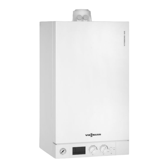
- Page 1 VIESMANN Installation and service instructions for contractors Vitodens 100-W Type WB1C, 6.5 to 35.0 kW Wall mounted gas condensing boiler Natural gas and LPG version For applicability, see the last page VITODENS 100-W Please keep safe. 5624 622 GB 9/2012...
-
Page 2: Safety Instructions
Safety instructions Safety instructions Please follow these safety instructions closely to prevent accidents and mate- rial losses. Safety instructions explained ■ all current safety regulations as defined by DIN, EN, DVGW, TRGI, Danger TRF, VDE and all locally applicable This symbol warns against the standards, risk of injury. - Page 3 ■ When using gas as fuel, also close the For replacements, use only orig- main gas shut-off valve and safeguard inal spare parts from Viessmann against unauthorised reopening. or those which are approved by ■ Isolate the system from the power sup- Viessmann.
-
Page 4: Table Of Contents
Index Index Installation instructions Preparing for installation Product information....................Preparing for installation..................Installation sequence Fitting the boiler and making connections............10 Opening the control unit casing................14 Electrical connections................... 15 Service instructions Commissioning, inspection, maintenance Steps - commissioning, inspection and maintenance.......... 19 Further details regarding the individual steps............ - Page 5 Index Index (cont.) Certificates Declaration of conformity..................72 Keyword index....................73...
-
Page 6: Preparing For Installation Product Information
Preset for operation with natural gas. Preparing for installation Product information Vitodens 100-W, type WB1C The Vitodens 100-W should generally only be delivered to those countries Preset for operation with natural gas. specified on the type plate. For deliveries to alternative countries, an approved... - Page 7 Preparing for installation Preparing for installation (cont.) Preparing for the boiler installation Dimensions and connections 58 58 A Heating flow E Heating return B Gas condensing boiler: F Condensate drain/safety valve Cylinder flow drain: Plastic hose 7 22 mm Gas condensing combi boiler: C Gas connection D Gas condensing boiler: Cylinder return...
- Page 8 Preparing for installation Preparing for installation (cont.) Fitting the wall mounting bracket Ø10 A Vitodens installation template...
- Page 9 Preparing for installation Preparing for installation (cont.) 1. Position the supplied installation tem- plate on the wall. 2. Mark out the rawl plug holes. 3. Drill 7 10 mm holes and insert the rawl plugs supplied. 4. Fit wall mounting bracket with screws supplied.
-
Page 10: Installation Sequence
Installation sequence Fitting the boiler and making connections Removing the front panel and mounting the boiler 1. Undo screws at the bottom of the 3. Hook the boiler into the wall mounting boiler; do not remove completely. bracket. 2. Remove front panel. -
Page 11: Gas Connection
Installation sequence Fitting the boiler and making connections (cont.) Making the connections on the water side For fittings on the heating water side and DHW side, see separate installation instructions. ¨ A Heating flow D Gas condensing boiler: Cylinder return B Gas condensing boiler: Gas condensing combi boiler: Cylinder flow... - Page 12 Installation sequence Fitting the boiler and making connections (cont.) 2. Carry out a tightness test. Note Only use suitable leak detection agents (EN 14291) and devices to check for leaks. Leak detection agents with unsuitable constituents (e.g. nitrites, sulphides) can cause material damage.
-
Page 13: Filling The Siphon With Water
Installation sequence Fitting the boiler and making connections (cont.) Connection, safety valve and condensate drain Connect condensate drain A with a constant fall and pipe vent to the public sewage system. Observe the local waste water regula- tions. Note Fill the siphon with water before com- missioning. -
Page 14: Opening The Control Unit Casing
Installation sequence Fitting the boiler and making connections (cont.) Balanced flue connection Connect the balanced flue. Flue system installation instruc- tions. Opening the control unit casing... -
Page 15: Electrical Connections
Installation sequence Opening the control unit casing (cont.) Please note Before beginning work, touch Electronic assemblies can be earthed objects, such as heating damaged by electrostatic dis- or water pipes, to discharge static charge. loads. Electrical connections Information on connecting accessories When connecting accessories observe the separate installation... - Page 16 Installation sequence Electrical connections (cont.) % Cylinder temperature sensor (plug For operation without a DHW cylin- on the cable harness outside the der, set rotary selector " tw " to "0". control unit) Note Gas condensing boiler without DHW cylinder: Cable entry A Power cable, remote control con- necting cable...
-
Page 17: Power Supply
Installation sequence Electrical connections (cont.) Vitotrol 100 connection 1 L N A Vitotrol 100, type UTDB C Jumper, remove when making this B Terminals "X1" on the control unit connection Recommended connecting cable ■ 2-core cable with a cross-section of 1.5 mm²... - Page 18 Installation sequence Electrical connections (cont.) Routing cables/leads and closing the control unit casing Please note When routing and securing Connecting cables will be dam- cables/leads on site, ensure that aged if they touch hot compo- the maximum permissible tem- nents. peratures for these cables/leads are not exceeded.
-
Page 19: Commissioning, Inspection, Maintenance
Commissioning, inspection, maintenance Steps - commissioning, inspection and maintenance For further information regarding the individual steps, see the page indicated Commissioning steps Inspection steps Maintenance steps Page • • • 1. Filling the heating system..........20 • • • 2. Venting the boiler by flushing........22 •... -
Page 20: Further Details Regarding The Individual Steps
Commissioning, inspection, maintenance Further details regarding the individual steps Filling the heating system Fill water ■ An antifreeze additive suitable for heating systems can be Please note added to the fill water. The anti- Unsuitable fill water increases freeze manufacturer must ver- the level of deposits and corro- ify its suitability. - Page 21 Commissioning, inspection, maintenance Further details regarding the individual steps (cont.) 3. Turn rotary selector "rt" fully anti- clockwise for less than 2 s and then return it clockwise into its control range. "SERV", "r" and "w" will appear on the display. Filling has been acti- vated.
-
Page 22: Venting The Boiler By Flushing
Commissioning, inspection, maintenance Further details regarding the individual steps (cont.) Venting the boiler by flushing 1. Connect the drain hose on shut-off valve A to a drain. 2. Close shut-off valve B. 3. Open valves A and C and flush at mains pressure, until no sound of escaping air can be heard. - Page 23 Commissioning, inspection, maintenance Further details regarding the individual steps (cont.) 6. Check the supply (flow) pressure. Set value: ■ Natural gas: 20 mbar ■ LPG: 37 mbar Note Use a suitable measuring device with a resolution of at least 0.1 mbar to check the supply pressure.
-
Page 24: Reducing The Max. Heating Output
Commissioning, inspection, maintenance Further details regarding the individual steps (cont.) Supply pressure (flow pressure) Action For natural gas For LPG less than 17.4 mbar less than 25 mbar Do not start the boiler. Notify your gas supply utility or LPG supplier. 17.4 to 25 mbar 25 to 47 mbar Start the boiler. -
Page 25: Checking The Co 2 Content
Commissioning, inspection, maintenance Further details regarding the individual steps (cont.) 3. Select the required max. heating out- put with rotary selector "tr". Bars for the selected heating output flash on the display. °C ■ Position 1 (1 bar) = lower heating output. - Page 26 Commissioning, inspection, maintenance Further details regarding the individual steps (cont.) 01. Connect a flue gas analyser at flue gas port A on the boiler flue con- nection. 02. Start the boiler and check for leaks. Danger Escaping gas leads to a risk of explosion.
- Page 27 Commissioning, inspection, maintenance Further details regarding the individual steps (cont.) 06. Adjust the lower heating output: Turn rotary selector "tr" to the control range on the left until the dis- play shows 1 bar for the lower heat- ing output. 07.
-
Page 28: Burner Removal
Commissioning, inspection, maintenance Further details regarding the individual steps (cont.) Burner removal F 4x 1. Switch off the power. 5. Undo gas supply pipe fitting E. 2. Shut off the gas supply. 6. Undo four screws F and remove the burner. -
Page 29: Checking The Burner Gasket And Burner Gauze Assembly
Commissioning, inspection, maintenance Further details regarding the individual steps (cont.) Checking the burner gasket and burner gauze assembly Check burner gasket A for damage and Replace the burner gauze assembly if it replace if required. is damaged. 1. Remove electrode B. 4. -
Page 30: Checking And Adjusting Electrode
Commissioning, inspection, maintenance Further details regarding the individual steps (cont.) Checking and adjusting electrode 1. Check the electrode for wear and contamination. 2. Clean the electrode with a small brush (not with a wire brush) or emery paper. 3. Check the electrode gaps. If the gaps are not as specified or the electrode is damaged, replace and align the electrode together with a new gasket. -
Page 31: Checking The Condensate Drain And Cleaning The Siphon
Commissioning, inspection, maintenance Further details regarding the individual steps (cont.) 1. Use a vacuum cleaner to remove deposits from heat exchanger A inside the combustion chamber. 2. If required, spray slightly acidic, chloride-free cleaning agents based on phosphoric acid onto heat exchanger A and let the solution soak in for at least 20 min. -
Page 32: Burner Installation
Commissioning, inspection, maintenance Further details regarding the individual steps (cont.) Burner installation A 4x 1. Fit the burner and tighten four screws 5. Reopen gas supply and switch on A diagonally to a torque of 8.5 Nm. power supply. 2. Insert new gasket and tighten the fit- tings on gas supply pipe B. -
Page 33: Checking The Diaphragm Expansion Vessel And System Pressure
Commissioning, inspection, maintenance Further details regarding the individual steps (cont.) 6. Check the gas connections for tight- Please note ness. The use of leak detection spray can result in incorrect Danger functions. Escaping gas leads to a risk of Leak detection spray must not explosion. -
Page 34: Mounting The Front Panel
Commissioning, inspection, maintenance Further details regarding the individual steps (cont.) Checking all gas equipment for tightness at operating pressure Danger Please note Escaping gas leads to a risk of The use of leak detection spray explosion. can result in incorrect functions. Check gas equipment for tight- Leak detection spray must not ness. -
Page 35: Instructing The System User
Commissioning, inspection, maintenance Further details regarding the individual steps (cont.) Instructing the system user The system installer should hand the operating instructions to the system user and instruct the user in operating the system. -
Page 36: Troubleshooting
Troubleshooting Function sequence and possible faults Display Action Control unit issues Increase set value a heat demand and ensure heat is drawn off Fan starts After approx. 1 min Check the fan, fan fault F9 connecting cables, power at the fan and fan control Ignition Fault F4... -
Page 37: Fault Messages On The Display
Troubleshooting Function sequence and possible faults (cont.) Burner in opera- Stops below the set Check the flue sys- tion boiler water tem- tem for tightness perature and re- (flue gas recircula- starts immediately tion), check the gas flow pressure Fault messages on the display Faults are indicated by a flashing fault code with fault symbol "U"... - Page 38 Troubleshooting Fault messages on the display (cont.) Displayed System characteris- Cause Measures fault code tics No DHW heating Short circuit, outlet Check the sensor (see temperature sen- page 47). Burner blocked Short circuit, flow Check connections and sensor lead; replace sensor if re- quired.
- Page 39 Troubleshooting Fault messages on the display (cont.) Displayed System characteris- Cause Measures fault code tics Burner in a fault The temperature Check heating system fill state limiter has respon- level. Check circulation pump. Vent the system. Check the temperature limiter and connecting leads (see page 46).
- Page 40 Troubleshooting Fault messages on the display (cont.) Displayed System characteris- Cause Measures fault code tics Burner blocked Fault, burner con- Check ignition electrodes trol unit and connecting cables. Check whether a strong interference (EMC) field exists near the appliance. Press "Reset" (see page 40).
-
Page 41: Repairs
Troubleshooting Repairs Removing the front panel 1. Undo screws at the bottom of the 2. Remove front panel. boiler; do not remove completely. -
Page 42: Outside Temperature Sensor
Troubleshooting Repairs (cont.) Outside temperature sensor 1. Open the control unit casing. See page 14. 2. Disconnect leads from outside tem- perature sensor. 4 3 2 1 3. Check the sensor resistance and compare it with the curve. 4. Replace the sensor in the case of severe deviation. -
Page 43: Boiler Water Temperature Sensor
Troubleshooting Repairs (cont.) Boiler water temperature sensor 1. Pull the leads from boiler water tem- perature sensor A and check the resistance. - Page 44 Troubleshooting Repairs (cont.) 2. Check the sensor resistance and compare it with the curve. 3. In the case of severe deviation, drain the boiler on the heating water side and replace the sensor. Danger The boiler water temperature sensor is immersed in the heating water (risk of scald- 10 30 50 70 90 110 ing).
- Page 45 Troubleshooting Repairs (cont.) 2. Compare the sensor resistance with the curve. 3. Replace the sensor in the case of severe deviation. 10 30 50 70 90 110 Temperature in °C...
- Page 46 Troubleshooting Repairs (cont.) Checking the temperature limiter If the burner control unit cannot be reset after a fault shutdown, although the boiler water temperature is below approx. 95 °C, check the temperature limiter. 1. Pull the leads from temperature lim- iter A.
- Page 47 Troubleshooting Repairs (cont.) Checking the outlet temperature sensor (gas condensing combi boiler) 1. Pull leads from outlet temperature sensor A. 2. Check the sensor resistance and compare it with the curve. 3. Replace the sensor in the case of severe deviation. Note Water can leak when replacing the outlet temperature sensor.
- Page 48 Troubleshooting Repairs (cont.) Checking the flue gas temperature sensor 1. Pull leads from flue gas temperature sensor A. 2. Check the sensor resistance and compare it with the curve.
- Page 49 Troubleshooting Repairs (cont.) 3. Replace the sensor in the case of severe deviation. 10 30 50 70 90 110 Temperature in °C Replace flow limiter (gas condensing combi boiler) 1. Drain the boiler from the DHW side. 2. Pivot the control unit downwards. 3.
- Page 50 Troubleshooting Repairs (cont.) Serial no. Flow rate Colour Serial no. Flow rate Colour (Type l/min (Type l/min plate) plate) 7499438 White 7499443 7499440 Black 7499447 Brown Checking or replacing the plate heat exchanger (gas condensing combi boiler) C Heating water flow E Cold water D Heating water return F DHW...
- Page 51 Troubleshooting Repairs (cont.) 3. Undo two screws A on plate heat 6. Install in reverse order using new exchanger B and remove plate heat gaskets. exchanger with gaskets. Note During installation, ensure that fixing Note holes are aligned and gaskets seated During removal, small amounts of correctly.
- Page 52 Troubleshooting Repairs (cont.) 3. Check fuse F4.
-
Page 53: Gas Type Conversion
Gas type conversion Converting from LPG to natural gas Removing gas restrictor 1. Pull cable from gas train A. 6. Remove or void gas type sticker on the top of the boiler (next to the type plate). 2. Remove union nut B. 7. - Page 54 Gas type conversion Converting from LPG to natural gas (cont.) 2. Turn both rotary selectors "tw" and "tr" simultaneously into their respective central positions. "SERV" appears on the display. 3. Turn rotary selector "tr" within 2 s fully anticlockwise. "A" and the newly selected value flash on the display.
-
Page 55: Control Unit
Control unit Functions and operating conditions in weather-compensated mode In weather-compensated operation, the boiler water temperature is regulated according to the outside temperature. Heating curve of the weather-compensated control unit -5 -10 -15 -20 Outside temperature in °C Setting of rotary selector "tr" Frost protection function A = 1 B = 2... -
Page 56: Designs
Designs Connection and wiring diagram Stepper motor diverter valve Vitotrol 100, types UTA and UTDB-RF Ignition/ionisation Vitotrol 100, type RT... - Page 57 Designs Connection and wiring diagram (cont.) Vitotrol 100, type UTDB Outlet temperature sensor (gas Power supply 230 V/50 Hz condensing combi boiler) Remote control (OpenTherm Cylinder temperature sensor (gas condensing boiler) device) Flue gas temperature sensor Outside temperature sensor (accessory) sÖ...
-
Page 58: Parts Lists
Parts lists Ordering parts The following information is required: Standard parts are available from your ■ Serial no. (see type plate A) local supplier. ■ Assembly (from this parts list) ■ Position number of the individual part within the assembly (from this parts list) -
Page 59: Overview Of The Assemblies
Parts lists Overview of the assemblies A Type plate D Control unit assembly B Sheet metal parts assembly E Heat cell assembly C Hydraulic assembly F Miscellaneous assembly... -
Page 60: Sheet Metal Parts Assembly
Parts lists Sheet metal parts assembly 0001 Front panel 0005 Air box floor 0002 Profiled seal 0006 Diaphragm grommets (set) 0003 Logo 0007 Wall mounting bracket 0004 Strain relief upper part 0007 0002 0003 0002 0001 0005 0003 0006 0004... -
Page 61: Heat Cell Assembly
Parts lists Heat cell assembly 0001 Gasket DN 60 0009 Tee 0002 Boiler flue connection 0010 Gas pipe 0003 Boiler flue connection plug 0011 Gasket 17 x 24 x 2 (set) 0004 Flue gas gasket 0012 Burner 0005 Flue gas temperature sensor 0013 Thermal insulation block 0006 Heat exchanger 0014 Heat exchanger mounting (set) -
Page 62: Burner Assembly
Parts lists Burner assembly 0001 Burner gasket 0009 Radial fan 0002 Thermal insulation ring 0010 Gas valve 0003 Cylinder burner gauze assembly 0012 Venturi extension 0004 Burner gauze assembly gasket 0013 Gasket A 17 x 24 x 2 (set) 0005 Burner door 0014 Conversion kit G31 0006 Ionisation electrode gasket 0015 Gasket set G27... - Page 63 Parts lists Burner assembly (cont.) 0003 0002 0001 0004 0007 0006 0005 0004 0006 0013 0008 0009 0010 0014 0013 0012 0015 0016 0015...
-
Page 64: Hydraulic Assembly
Parts lists Hydraulic assembly 0001 Diaphragm expansion vessel 0011 Air vent valve G ⅜ 0002 Support block, diaphragm expan- 0012 Temperature sensor sion vessel 0013 Round sealing ring 8 x 2 0003 Gasket A 10 x 15 x 1.5 (set) 0014 Moulded hose heating water flow 0004 Connection line;... - Page 65 Parts lists Hydraulic assembly (cont.) 0002 0001 0003 0005 0007 0010 0003 0010 0007 0012 0018 0021 0010 0006 0007 0020 0007 0010 0004 0018 0003 0007 0009 0011 0009 0014 0013 0007 0007 0019 0007 0007 0016 0015 0019 0015 0016 0007...
-
Page 66: Hydraulic Assembly Circulation
Parts lists Hydraulic assembly circulation 0001 Air vent valve 0020 Hydraulics 0002 O-ring 34 x 3 0021 O-ring 19.8 x 3.6 (5 pce) 0005 Safety valve 0022 O-ring 16 x 3 (5 pce) 0008 Pump motor 0023 Check valve 0009 Bypass cartridge 0026 Clip Ø... -
Page 67: Combi Hydraulic Assembly
Parts lists Combi hydraulic assembly 0001 Air vent valve 0017 Water volume controller 0002 O-ring 34 x 3 (5 pce) 0018 Temperature sensor 0003 Plate heat exchanger 0019 Top-up tap key 0004 Gasket set, plate heat exchanger 0020 Hydraulics 0005 Safety valve 0021 Round sealing ring 19.8 x 3.6 0006 Clip Ø... -
Page 68: Control Unit Assembly
Parts lists Combi hydraulic assembly (cont.) 0020 0001, 0004, 0006, 0009, 0010, 0011, 0004 0003 0013, 0014, 0016, 0004 0017, 0018, 0021, 0024, 0026, 0030 0006 0015 0014 0014 0017 0016 0018 0016 0030 0001 0002 0002 0022 0027 0011 0023 0012 0021... - Page 69 Parts lists Control unit assembly (cont.) 0005 Cable harness X20 0008 Fan connecting cable 0006 Ignition cable with angled plug 0009 Cable harness stepper motor 5 kΩ 0010 Fuse 2.5 A (slow) 250 V 0007 Gas valve cable 0001 0002 0010 0003 0002...
-
Page 70: Miscellaneous Assembly
Parts lists Miscellaneous assembly 0001 Touch-up spray paint, white 0004 Operating instructions 0002 Touch-up paint stick, white 0005 Installation and service instruc- 0003 Special grease tions 0001 0002 0003 0004 0005... -
Page 71: Specification
Specification Specification Rated voltage: 230 V~ Temperature limiter Rated frequency: 50 Hz setting: 100 °C (fixed) Rated current: 2.0 A~ Backup fuse (power Safety category: supply): max. 16 A IP rating: IP X4 to EN 60529 Permissible ambient temperature ■ during operation: 0 to +40 °C ■... -
Page 72: Declaration Of Conformity
Certificates Declaration of conformity Declaration of Conformity for the Vitodens100-W We, Viessmann Werke GmbH&Co KG, D-35107 Allendorf, confirm as sole respon- sible body that the product Vitodens 100-W complies with the following standards: EN 297 EN 55 014-2 EN 483... -
Page 73: Keyword Index
Keyword index Keyword index Function sequence......36 Boiler water temperature sensor ..43 Fuse...........51 Burner gasket........29 Burner gauze assembly.....29 Burner installation......32 Gas connection........11 Burner removal........28 Gas supply pressure......23 Gas train ...........23 Gas type conversion......53 Cleaning the combustion chamber..30 ■ At the control unit......53 Cleaning the heat exchanger.....30 ■... - Page 74 Keyword index Keyword index (cont.) Reducing the heating output....24 Ventilation air pipe......14 Reset..........40 Venting..........22 Vitotrol 100 ■ Connection........17 Safety chain ........46 Safety valve........13 Siphon..........13, 31 Wall mounting........8 Spare parts........58 Wall mounting bracket......8 Specification ........71 Water quality........20 Static pressure........23 Weather-compensated mode.....55 Supply pressure.........22 System filling........20 System pressure......21, 33...
- Page 76 7499435 7499436 7499438 7499440 7499441 7499442 7499443 7499446 7499447 Viessmann Werke GmbH&Co KG Viessmann Limited D-35107 Allendorf Hortonwood 30, Telford Telephone: +49 6452 70-0 Shropshire, TF1 7YP, GB Fax: +49 6452 70-2780 Telephone: +44 1952 675000 www.viessmann.com Fax: +44 1952 675040...