Yamaha RX-V565 Service Manual
Av receiver/av amplifier
Hide thumbs
Also See for RX-V565:
- Service manual (150 pages) ,
- Owner's manual (136 pages) ,
- Firmware update procedures (5 pages)
Table of Contents
Advertisement
This manual has been provided for the use of authorized YAMAHA Retailers and their service personnel.
It has been assumed that basic service procedures inherent to the industry, and more specifi cally YAMAHA Products, are already known
and understood by the users, and have therefore not been restated.
WARNING:
IMPORTANT:
The data provided is believed to be accurate and applicable to the unit(s) indicated on the cover. The research, engineering, and service
departments of YAMAHA are continually striving to improve YAMAHA products. Modifications are, therefore, inevitable and
specifi cations are subject to change without notice or obligation to retrofi t. Should any discrepancy appear to exist, please contact the
distributor's Service Division.
WARNING:
IMPORTANT:
■ CONTENTS
TO SERVICE PERSONNEL ............................................2
FRONT PANELS .........................................................3-4
REAR PANELS ...........................................................5-9
REMOTE CONTROL PANEL ..........................................9
SPECIFICATIONS / 参考仕様 ................................. 10-16
INTERNAL VIEW .......................................................... 17
SERVICE PRECAUTIONS / サービス時の注意事項 ..... 17
DISASSEMBLY PROCEDURES / 分解手順 ........... 18-20
UPDATING FIRMWARE /
ファームウェアの書き込み .....................................21-32
ダイアグ(自己診断機能) .......................................33-66
1 0 1 1 3 3
AV RECEIVER/AV AMPLIFIER
RX-V565/HTR-6250/
Failure to follow appropriate service and safety procedures when servicing this product may result in personal injury,
destruction of expensive components, and failure of the product to perform as specifi ed. For these reasons, we advise
all YAMAHA product owners that any service required should be performed by an authorized YAMAHA Retailer or
the appointed service representative.
The presentation or sale of this manual to any individual or fi rm does not constitute authorization, certifi cation or
recognition of any applicable technical capabilities, or establish a principle-agent relationship of any form.
Static discharges can destroy expensive components. Discharge any static electricity your body may have
accumulated by grounding yourself to the ground buss in the unit (heavy gauge black wires connect to this buss).
Turn the unit OFF during disassembly and part replacement. Recheck all work before you apply power to the unit.
Copyright © 2009
This manual is copyrighted by YAMAHA and may not be copied or
redistributed either in print or electronically without permission.
AX-V565
SERVICE MANUAL
IMPORTANT NOTICE
DISPLAY DATA .......................................................67-68
IC DATA ...................................................................69-86
PIN CONNECTION DIAGRAMS .............................87-89
BLOCK DIAGRAMS ................................................90-93
PRINTED CIRCUIT BOARDS ................................94-111
SCHEMATIC DIAGRAMS ................................... 113-124
REPLACEMENT PARTS LIST ............................ 125-143
REMOTE CONTROL ........................................... 144-146
ADVANCED SETUP / 本機の設定を変更する ...... 147-148
All rights reserved.
P.O.Box 1, Hamamatsu, Japan
animate '09.03
Advertisement
Table of Contents

Related Manuals for Yamaha RX-V565


Summary of Contents for Yamaha RX-V565
-
Page 1: Table Of Contents
This manual has been provided for the use of authorized YAMAHA Retailers and their service personnel. It has been assumed that basic service procedures inherent to the industry, and more specifi cally YAMAHA Products, are already known and understood by the users, and have therefore not been restated. -
Page 2: To Service Personnel
RX-V565/HTR-6250/AX-V565 ■ TO SERVICE PERSONNEL AC LEAKAGE 1. Critical Components Information WALL EQUIPMENT TESTER OR Components having special characteristics are marked OUTLET UNDER TEST EQUIVALENT must be replaced with parts having specifications equal to those originally installed. 2. Leakage Current Measurement (For 120V Models Only) -
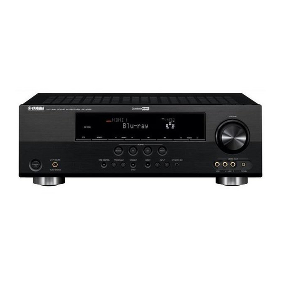
Page 3: Front Panels
RX-V565/HTR-6250/AX-V565 ■ FRONT PANELS Top view U, C, R, T, K, A, B, G, E, F, L models J model Front view RX-V565 (U, C, R, K, A, B, G, E, F, L models) RX-V565 (T model) - Page 4 RX-V565/HTR-6250/AX-V565 HTR-6250 (U, C, K, F models) AX-V565 (J model)
-
Page 5: Rear Panels
RX-V565/HTR-6250/AX-V565 ■ REAR PANELS RX-V565 (U model) RX-V565 (C model) RX-V565 (R model) - Page 6 RX-V565/HTR-6250/AX-V565 RX-V565 (T model) RX-V565 (K model) RX-V565 (A model)
- Page 7 RX-V565/HTR-6250/AX-V565 RX-V565 (B, G, E, F models) RX-V565 (L model) HTR-6250 (U model)
- Page 8 RX-V565/HTR-6250/AX-V565 HTR-6250 (C model) HTR-6250 (K model) HTR-6250 (F model)
-
Page 9: Remote Control Panel
RX-V565/HTR-6250/AX-V565 AX-V565 (J model) ■ REMOTE CONTROL PANEL RAV293 (U, C, R, T, K, A, B, G, E, F, L, J models) -
Page 10: Specifications / 参考仕様
RX-V565/HTR-6250/AX-V565 ■ SPECIFICATIONS / 参考仕様 ■ Audio Section / オーディオ部 ■ Video Section / ビデオ部 Minimum RMS Output Power (Power Amp. Section) / Video Signal Type / ビデオ信号方式 定格出力(パワーアンプ部) Gray back / グレーバック (1 kHz, 0.9 % THD) U, C, R, K, J models .............. NTSC FRONT L/R, CENTER, SURROUND L/R, SURROUND BACK L/R T, A, B, G, E, F, L models ............ - Page 11 F ....Russian model K ..... Korean model L ....Singapore model A ....Australian model J ....Japanese model “x.v.Color” is a trademark of Sony Corporation. 「x.v.Color」は、ソニー株式会社の商標です。 “SILENT CINEMA” is a trademark of Yamaha Corporation. 「サイレントシネマ™ SILENT CINEMA ™」はヤマハ株式会社の登録商標で す。 AAC ロゴマーク はドルビーラボラトリーズの商標です。...
- Page 12 RX-V565/HTR-6250/AX-V565 • DIMENSIONS / 寸法図 Top view Front view 395 (15-1/2") 435 (17-1/8") Unit: mm (inch) 単位 : mm(インチ) • SCENE TEMPLATE Name BD/DVD RADIO AV-1 AV-3 INPUT HDMI1 TUNER (Component / Optical) (Video / Coaxial) MUSIC ENHANCER Sound field mode...
- Page 13 RX-V565/HTR-6250/AX-V565 • SOUND FIELD PARAMETERS Category Program MOVIE ● Standard ● ● ● ● ● ● ● ● ● ● ● Spectacle ● ● ● ● ● ● ● ● ● ● ● Sci-Fi ● ● ● ● ● ●...
- Page 14 RX-V565/HTR-6250/AX-V565 • SET MENU TABLE / セットメニュー MAIN MENU SUB MENU PARAMETER VALUE [INITIAL VALUE] 1 • Speaker Setup 1 Auto Setup (YPAO) Extra SP Assign [Zone2] / Presence / None EQ Type [Natural] / Flat / Front Start [ENTER]: Start...
- Page 15 RX-V565/HTR-6250/AX-V565 MAIN MENU SUB MENU PARAMETER VALUE [INITIAL VALUE] 3 Volume Adaptive DRC Auto / [Off] Max Volume -30.0 dB to +15.0 dB / [+16.5 dB], 5.0 dB step Init. Volume [Off] / Mute / -80.0 to +16.5 dB, 0.5 dB step...
- Page 16 RX-V565/HTR-6250/AX-V565 MAIN MENU SUB MENU PARAMETER VALUE [INITIAL VALUE] DSP Level -6 to +3 dB, [0 dB] Init. Delay 1 to 99 ms P. Init. Dly S. Init. Dly 1 to 49 ms Room Size P. Room Size 0.1 to 2.0 S.
-
Page 17: Internal View
RX-V565/HTR-6250/AX-V565 ■ INTERNAL VIEW VIDEO (2) P.C.B. VIDEO (3) P.C.B. MAIN (3) P.C.B. (R, L models) MAIN (2) P.C.B. VIDEO (1) P.C.B. DIGITAL P.C.B. VIDEO (8) P.C.B. (J model) AM/FM TUNER VIDEO (9) P.C.B. (B, G, E, F models) OPERATION (2) P.C.B. -
Page 18: Disassembly Procedures / 分解手順
RX-V565/HTR-6250/AX-V565 ■ DISASSEMBLY PROCEDURES / 分解手順 (Remove parts in the order as numbered.) (番号順に部品を取り外してください。 ) Disconnect the power cable from the AC outlet. AC 電源コンセントから、電源コードを抜いてください。 1. Removal of Top Cover 1. トップカバーの外し方 a. Remove 4 screws ( ① ) and 5 screws ( ② ). (Fig. 1) a. - Page 19 RX-V565/HTR-6250/AX-V565 3. Removal of DIGITAL P.C.B. 3. DIGITAL P.C.B. の外し方 a. Remove 2 screws ( ⑥ ) and 5 screws ( ⑦ ). (Fig. 2) a. ⑥ のネジ 2 本、⑦ のネジ 5 本を外します。 (Fig. 2) b. Remove screw ( ⑧ ). (Fig. 2) b.
- Page 20 RX-V565/HTR-6250/AX-V565 When checking the P.C.B.s: P.C.B. をチェックする場合には: • Place the P.C.B.s (with rear panel) upright. (Fig. 3) ・ リアパネルと一緒に P.C.B. を立ち上げて置きます。 (Fig. 3) • Connect the ground points of the heat sink, rear pan- el and MAIN (1) P.C.B. (G1000) to the chassis with a ・...
-
Page 21: ファームウェアの書き込み
RX-V565/HTR-6250/AX-V565 ■ UPDATING FIRMWARE / ファームウェアの書き込み Note) The user memories (sound field parameters, 注意) ファームウェアの書き込みを行っても、ユーザー system memory, tuner presetting, etc.) are kept メモリー(音場プログラムのパラメーターやシス stored even when you write the firmware. テムメモリー、チューナープリセット等)は保持 されます。 When replacing the following parts, be sure to write the 下記の部品をサービス部品に交換した場合、最新のファー... - Page 22 RX-V565/HTR-6250/AX-V565 Writing method using the CD CD を使用して書き込む方法 ● Required Tools ● 必要なツール • DVD or CD player (with DIGITAL OUTPUT (OPTICAL ・ DVD ま た は CD プ レ ー ヤ ー(DIGITAL OUTPUT or COAXIAL) jack) (OPTICAL または COAXIAL)端子付き)...
- Page 23 RX-V565/HTR-6250/AX-V565 ● Connection ● 接続 Connect this unit and DVD/CD player as shown 本機と DVD/CD プレーヤーを下記のように接続しま below. (Fig. 1) す。 (Fig. 1) Example of OPTICAL jack / OPTICAL 端子使用例 This unit / 本機 DVD/CD player / DVD/CDプレーヤー Optical cable 光フ ァ イバーケーブル...
- Page 24 RX-V565/HTR-6250/AX-V565 ● Operation Procedures ● 操作手順 1. While pressing the “STRAIGHT” key of this unit, 1. 本機の STRAIGHT キーを押しながら、本機の電 connect the power cable of this unit to the AC 源コードを AC コンセントに接続します。 (Fig. 2) outlet. (Fig. 2) FIRMWARE UPDATE モ ー ド が 起 動 し、 CDDA The FIRMWARE UPDATE mode is activated and Upgrader が表示されます。...
- Page 25 RX-V565/HTR-6250/AX-V565 ※ 本機に既存のファームウェアと、書き込もう When the version of the firmware to be written is the same as the one existing in this unit, としているファームウェアのバージョンが同 “Same Version”, “Please...” and “Power off!!” じ場合、 Same Version 、 Please... 、 Power are displayed repeatedly. (Upgrading is not off!! の表示が繰り返されます。...
- Page 26 RX-V565/HTR-6250/AX-V565 Writing method using PC (RS232C) PC(RS232C)を使用して書き込む方法 ● Required Tools ● 必要なツール • Firmware downloader program ・ ファームウェア書き込み用プログラム For microprocessor: DSP_FLASHER_v3.0.exe マイコン用: DSP_FLASHER_v3.0.exe For DSP (TI flash ROM): DSP(TI fl ash ROM)用: DSP_FLASHER Ver2.7.exe DSP_FLASHER Ver2.7.exe • Firmware ・ ファームウェア...
- Page 27 RX-V565/HTR-6250/AX-V565 ● Connection ● 接続 1. Remove the top cover. (See “DISASSEMBLY 1. トップカバーを取り外します。 ( 分解手順 参照) PROCEDURES”) 2. 本機の書き込み用ポート(DIGITAL P.C.B. CB27) 2. Connect the writing port (CB27 of DIGITAL P.C.B.) と PC のシリアルポート(RS232C)を下記のよう of this unit to the serial port (RS232C) of the PC に接続します。...
- Page 28 RX-V565/HTR-6250/AX-V565 ● Operation Procedures ● 操作手順 Writing to the microprocessor マイコンへの書き込み With the power cable of this unit unconnected to the 本機の電源コードを AC コンセントに接続していない AC outlet, start up DSP_FLASHER_v3.0.exe. 状態で、DSP_FLASHER_v3.0.exe を起動します。 The screen appears as shown below. (Fig. 2) 下記の画面が表示されます。 (Fig. 2)...
- Page 29 RX-V565/HTR-6250/AX-V565 Connect the power cable of this unit to the AC outlet. 本機の電源コードを AC コンセントに接続します。 Click [E.P.] to start writing. (Fig. 3) 4. [E.P.] をクリックして書き込みを開始します。 (Fig. 3) When writing of the firmware is completed, “Program ファームウェアの書き込みが完了すると、 Program Finished!” is displayed. (Fig. 3) Finished! が表示されます。...
- Page 30 RX-V565/HTR-6250/AX-V565 Writing to DSP DSP への書き込み With the power cable of this unit unconnected to the 本機の電源コードを AC コンセントに接続していない AC outlet, start up DSP_FLASHER Ver2.7.exe. 状態で、DSP_FLASHER Ver2.7.exe を起動します。 The screen appears as shown below. (Fig. 4) 下記の画面が表示されます。 (Fig. 4) Click [Vx61 DSP]. (Fig. 4) 2.
- Page 31 RX-V565/HTR-6250/AX-V565 Click [RDY]. (Fig. 6) 4. [RDY]をクリックします。 (Fig. 6) Fig. 6 While pressing the “DIRECT” key of this unit, connect 本機の DIRECT キーを押しながら、本機の電源コー the power cable of this unit to the AC outlet. (Fig. 7) ドを AC コンセントに接続します。 (Fig. 7)...
- Page 32 RX-V565/HTR-6250/AX-V565 When writing of the firmware is completed, “Vx61 ファームウェアの書き込みが完了すると、 Vx61 DSP DSP Flash finished!” is displayed. (Fig. 3) Flash fi nished! が表示されます。 (Fig. 3) Click [EXIT] to end DSP_FLASHER_v2.7.exe. (Fig. 8) 7. [EXIT]をクリックして DSP_FLASHER_v2.7.exe を終 了します。 (Fig. 8) Fig. 8 Start up the self-diagnostic function and select “25.
-
Page 33: Self-Diagnostic Function / ダイアグ(自己診断機能
RX-V565/HTR-6250/AX-V565 ■ SELF-DIAGNOSTIC FUNCTION / ダイアグ(自己診断機能) This unit has self-diagnostic functions that are intended 本機には、検査、測定、不良個所の発見を目的にしたダ for inspection, measurement and location of faulty point. イアグ(自己診断機能)があります。 There are 25 main menu items, each of which has sub- メ イ ン メ ニ ュ ー は 25 個 あ り、 そ の そ れ ぞ れ に サ ブ メ... - Page 34 RX-V565/HTR-6250/AX-V565 Main menu Sub-menu XM STATUS (U model) 4 XM Tone /44kHz Not applied to these models. / このモデルには適用 5 ISO Tone /44kHz されません。 6 1k -1dB /32kHz 7 1k -61dB /32kHz 8 Mute /32kHz 9 XM Tone /32 kHz...
- Page 35 RX-V565/HTR-6250/AX-V565 ● Starting Self-Diagnostic Function ● ダイアグの起動 While pressing those 2 keys of this unit as shown in the 本機の下図に示す 2 つのキーを押しながら STANDBY/ figure below, press the “STANDBY/ON” key to turn on the ON キーを押して電源を入れます。 power. ダイアグが起動します。 The self-diagnostic function mode is activated.
- Page 36 RX-V565/HTR-6250/AX-V565 ● Display provided when Self-Diagnostic ● ダイアグ起動時の表示 Function started 本機の FL ディスプレイにプロテクション履歴情報が表示 The FL display of this unit displays the protection されます。数秒後、メインメニュー No. 1 BYPASS のサブ function history data then the main menu (sub-menu メニュー 1. ANALOG BYPAS が表示されます。...
- Page 37 RX-V565/HTR-6250/AX-V565 When there is a history of protection function due to abnormal DC output DC 出力異常によるプロテクション履歴がある場合 P R D P R T : x x x AD value when the protection function is working/ 電圧の A/D 変換値 Cause: DC output from the power amplifier is abnormal.
- Page 38 RX-V565/HTR-6250/AX-V565 When there is a history of protection function due to excessive heat sink temperature ヒートシンクの異常温度によるプロテクション履歴がある場合 T H M P R T : x x x AD value when the protection function is working/ 電圧の A/D 変換値 Cause: The temperature on the heat sink is excessive.
- Page 39 RX-V565/HTR-6250/AX-V565 ● Operation procedure of Main menu ● メインメニューとサブメニューの操作 and Sub-menu ダイアグには No. 1 ∼ 25 のメインメニューがあり、その There are 25 main menu items, each of them having sub- それぞれにサブメニューがあります。 menu items. メインメニューの選択 Main menu selection SCENE TV (順送り) 、 SCENE BD/DVD (逆送り)キー...
- Page 40 RX-V565/HTR-6250/AX-V565 ● Details of Self-Diagnostic Function menu ● ダイアグメニュー詳細 1. BYPASS 1. BYPASS Using the sub-menu, it is possible to select ANALOG サブメニューにより、ANALOG BYPASS/DSP BYPASS BYPASS output or DSP BYPASS output. が選択可能です。 ANALOG BYPASS ANALOG BYPASS The analog input audio signal is output to FRONT L/R in アナログ入力の音声信号が...
- Page 41 RX-V565/HTR-6250/AX-V565 DSP BYPASS FL / FR LC89058 (DECODE) C / SW (POST PROCESSING) TI D70Y SL / SR SBL / SBR PCM1803 DRAM (Shaded items not used in this example) 2. RAM THROUGH 2. RAM THROUGH Using the sub-menu, it is possible to select MARGIN サブメニューにより、MARGIN/FULL BIT が選択可能...
- Page 42 RX-V565/HTR-6250/AX-V565 RAM FULL BIT RAM FULL BIT The audio signal is output in digital full bit without 音声信号がヘッドマージンを含まず、デジタルフルビッ including the head margin. トで出力されます。 The SUBWOOFER signal is output but not in digital full SUBWOOFER は出力されますが、デジタルフルビットで bit. はありません。 2 . R A M F U L L A L L...
- Page 43 RX-V565/HTR-6250/AX-V565 RAM FULL CENTER RAM FULL CENTER The audio signal is output to only CENTER in digital full 音声信号がヘッドマージンを含まず、デジタルフルビッ bit without including the head margin. トで CENTER のみへ出力されます。 2 . R A M F U L L C INPUT: AV5 ANALOG...
- Page 44 RX-V565/HTR-6250/AX-V565 3. HDMI AUDIO 3. HDMI AUDIO Using the sub-menu, the audio signals input to HDMI サブメニューにより、HDMI IN に入力された音声信号 IN are selected and output. が選択、出力されます。 When selecting “DSD”, be sure to connect an ※ DSD を選択する場合、必ず DSD 出力が可能な HDMI unit equipped with DSD output function to HDMI 機器を接続してください。...
- Page 45 RX-V565/HTR-6250/AX-V565 4. SPEAKER SET 4. SPEAKER SET The analog switch settings for each sub-menu are as 各サブメニューにおけるアナログスイッチの設定は shown in the table below. 以下の通りです。 FRONT CENTER SURROUND SURROUND BACK SUBWOOFER FRNT : SML 0dB SMALL LARGE LARGE LARGE SWFR CENTER : NONE...
- Page 46 RX-V565/HTR-6250/AX-V565 FRONT : SML 0dB 4 . F R N T : S M L 0 d B The FRONT L/R signal, when 90 Hz or lower, is mixed to the channel specified by LFE/BASS. 90 Hz 以下の信号が LFE/BASS で指定したチャンネルへミックスされて出力されます。...
- Page 47 RX-V565/HTR-6250/AX-V565 5. MULTI CH-INPUT 5. MULTI CH-INPUT 8 ch INPUT 6 ohms 8 ch INPUT 6 ohms Not applied to these models. このモデルには適用されません。 5 . 8 c h I N P U T _ 6 ^ INPUT: MULTI CH INPUT...
- Page 48 RX-V565/HTR-6250/AX-V565 LIM / PLDET / THM LIM / PLDET / THM LIM: Setting value of LIM (Limiter control) LIM: LIM(リミッター制御)の設定値 Do not change the value settings because ※ 開発スタッフ専用メニューですので、設定値 this menu is only for the use of development の変更は行わないでください。 staff.
- Page 49 RX-V565/HTR-6250/AX-V565 FL/OSD CHECK 7. FL/OSD CHECK This menu is used to to check the FL display and FL 表示部および映像表示部のチェックプログラムで video control sections. When checking the video す。映像制御部をチェックする場合には、 TV モニター control section, connect a TV monitor to this unit with と本機をコンポーネント /D ビデオケーブル、S ビデ...
- Page 50 RX-V565/HTR-6250/AX-V565 Segment conditions of the FL driver and the FL tube 全セグメント消灯・全セグメント点灯により FL ドラ are checked by turning ON and OFF all segments. イバー、FL 管のセグメントの不良を確認します。 Next, the operation of the FL driver is checked by 次に、ディマーコントロールによって FL ドライバー using the dimmer control. Then a short between seg- の動作チェックを行います。...
- Page 51 RX-V565/HTR-6250/AX-V565 9. A/D DATA CHECK 9. A/D DATA CHECK This menu is used to display the A/D conversion 本機パネルキー、プロテクションなどを検出してい value of the microprocessor which detects panel keys るマイコンの A/D 変換値を、サブメニューで表示し of this unit and protection functions by using the sub- ます。...
- Page 52 RX-V565/HTR-6250/AX-V565 DC/TH DC/TH Power amplifier DC (DC voltage) output is DC: パワーアンプ DC(直流電圧)出力の検出 detected. 正常値: 23 ∼ 70 Normal value: 23 to 70 (基準電圧:3.3 V = 255) (Reference voltage: 3.3 V=255) Temperature on the heat sink is detected. TH: ヒートシンク温度の検出...
- Page 53 RX-V565/HTR-6250/AX-V565 DST/DK DST/DK DST: Destination detection DST: 仕向け先の検出 (Reference voltage: 3.3 V=255) (基準電圧:3.3 V = 255) DOCK type detection DK: DOCK タイプの検出 (Reference voltage: 3.3 V=255) (基準電圧:3.3 V = 255) D S T : 0 2 7 D K : 2 5 5...
- Page 54 RX-V565/HTR-6250/AX-V565 10. VIDEO CHECK 10. VIDEO CHECK I2C check I2C check The I2C (Inter integrated circuit) bus line connection is I2C(Inter integrated circuit)バスラインの接続をチェッ checked. クします。 0 : No error detected / 不良検出なし I 2 C : 0 0 0 0 0 0 0 0 1 : An error is detected / 不良検出あり...
- Page 55 RX-V565/HTR-6250/AX-V565 Digital CVBS (Video) Digital CVBS(Video) The video signal is converted and output as shown below. 映像信号が以下のように変換され、出力されます。 D I G I T A L C V B S Digital CVBS (Video) DIGITAL DIGITAL IC71 ABT1012 DIGITAL DIGITAL Sil9134 I/P SCALER...
- Page 56 RX-V565/HTR-6250/AX-V565 Analog bypass Analog bypass The video signal is converted and output as shown below. 映像信号が以下のように変換され、出力されます。 A N A L O G B Y P A S S Analog bypass DIGITAL DIGITAL IC71 ABT1012 DIGITAL DIGITAL Sil9134 I/P SCALER IC70...
- Page 57 RX-V565/HTR-6250/AX-V565 11. XM STATUS (U model) Not applied to these models. 1 kHz, -1 dB / 44.1 kHz 1 k - 1 d B / 4 4 1 kHz, -61 dB / 44.1 kHz 1 k - 6 1 d B / 4 4 Mute / 44.1 kHz...
- Page 58 RX-V565/HTR-6250/AX-V565 12. SIRIUS (U model) Not applied to these models. SIRIUS: S I R I U S : - - S R : F F 0 0 F F SSP: S S P : 0 0 0 0 0 0...
- Page 59 RX-V565/HTR-6250/AX-V565 14. DOCK 14. DOCK This menu is used to check the DOCK connector iPod 本体無しで、DOCK コネクターの検査を行うメ without the iPod itself. ニューです。 With the power to this unit turned off, short between 本機の電源を切った状態で、DOCK コネクターの 14 pins No. 14 (TX) and No. 18 (RX), between pins No.
- Page 60 HDMI モジュールに書き込まれている本機のプロダクト ID が表示されます。 3138 : RX-V565 3139 : HTR-6250 313A : AX-V565 HDMI vendor name V N : Y A M A H A The vendor name “YAMAHA” of this unit written in HDMI module is displayed. HDMI モジュールに書き込まれている本機のベンダー名“YAMAHA”が表示されます。...
- Page 61 RX-V565/HTR-6250/AX-V565 16. HDMI SELECT 16. HDMI SELECT Using the sub-menu, the selected input signal is サブメニューにより , 選択された入力信号が HDMI output to HDMI OUT. OUT へ出力されます。 ※ SUPPORT AUDIO は OTHER に設定されます。 Support audio is set to “OTHER”. HDMI none H D M I N O N E No signal is output.
- Page 62 RX-V565/HTR-6250/AX-V565 HDMI up-conversion through DIGITAL DIGITAL IC71 ABT1012 DIGITAL DIGITAL Sil9134 I/P SCALER IC70 Sil9233A ADV7800 Up-conversion through VIDEO DECODER IC309 LC74782 17. USB 17. USB Not applied to these models. このモデルには適用されません。 USB file 1 USB fi le 1 1 7 : U S B f i l e 1 USB file 2 USB fi...
- Page 63 RX-V565/HTR-6250/AX-V565 18. IF STATUS (Input function status) 18. IF STATUS(Input function status) Not applied to these models. このモデルには適用されません。 DSP status DSP status D S T : 7 7 0 0 0 2 0 0 0 0 19. BUS CHECK 19. BUS CHECK Communication and bus line connection between DSP P.C.B.
- Page 64 RX-V565/HTR-6250/AX-V565 20. NO MENU (Invalidity) 20. NO MENU(Invalidity) I n v a l i d i t y 21. PROTECTION HISTORY 21. PROTECTION HISTORY The history of protection function is displayed. 過去のプロテクション履歴が表示されます。 Select this menu and press the “STRAIGHT” key, and サブメニューを選んだ後、...
- Page 65 RX-V565/HTR-6250/AX-V565 24. FACTORY PRESET 24. FACTORY PRESET This menu is used to reserve and inhibit initialization バックアップ用 IC(音場プログラムのパラメーター of the back-up IC. やセットメニュー内容等)の初期化を予約/禁止し ます。 PRESET INHIBIT (Initialization inhibited) / PRESET INHIBIT(初期化禁止) 2 4 . P R E S E T I N H I Back-up IC initialization is not executed.
- Page 66 231 ±4 Destination B, G, E, F MODEL detection value Detection value 46 ±4 72 ±4 Model name V5 (RX-V565, AX-V565) H5 (HTR-6250) VERIFY error V e r i f y 0 0 0 Not applied to these models. このモデルには適用されません。...
-
Page 67: Display Data
RX-V565/HTR-6250/AX-V565 ■ DISPLAY DATA ● V4001 : 18-MT-09GNK (OPERATION P.C.B.) PATTERN AREA ● PIN CONNECTION Pin No. 68 67 Connection F2 NX 29 28 Pin No. Connection Note : 1) F1, F2 ..Filament pin 2) NP ..No pin 3) NX .. - Page 68 RX-V565/HTR-6250/AX-V565 ● ANODE CONNECTION 1G-14G –...
-
Page 69: Ic Data
RX-V565/HTR-6250/AX-V565 ■ IC DATA IC44: D70YE101BRFP266 (DIGITAL P.C.B.) Decoder/Post processor * No replacement part available. / サービス部品供給なし SPI0_SIMO EM_CKE SPI0_SOMI/I2C0_SDA EM_CLK AXR0[0] EM_WE_DQM[1] AXR0[1] EM_D[8] AXR0[2] AXR0[3] EM_D[9] EM_D[10] AXR0[4] AXR0[5]/SPI1_SCS EM_D[11] AXR0[6]/SPI1_ENA AXR0[7]/SPI1_CLK EM_D[12] EM_D[13] EM_D[14] AXR0[8]/AXR1[5]/SPI1_SOMI EM_D[15] AXR0[9]/AXR1[4]/SPI1_SIMO... - Page 70 RX-V565/HTR-6250/AX-V565 Function Name TYPE PULL GPIO Detail of Function (P.C.B.) AHCLKX0/AHCLKX2 – McASP0 and McASP2 transmit master clock AMUTE0 – McASP0 mute output AMUTE1 – McASP1 mute output AHCLKX1 – McASP1 transmit master clock ACLKX1 – McASP1 transmit bit clock...
- Page 71 RX-V565/HTR-6250/AX-V565 Function Name TYPE PULL GPIO Detail of Function (P.C.B.) EM_D[10] – EMIF data bus [lower 16-Bits] EM_D[9] – EMIF data bus [lower 16-Bits] CVDD EM_D[8] – EMIF data bus [lower 16-bits] EM_WE_DQM[1] – Write enable or byte enable for EM_D [15:8]...
- Page 72 RX-V565/HTR-6250/AX-V565 Function Name TYPE PULL GPIO Detail of Function (P.C.B.) 123 CVDD 124 VSS 125 DVDD McASP0 serial data 8 or McASP1 serial data 5 or SPI1 data pin slave 126 /SPI1_SOMI – out master in McASP0 serial data 9 or McASP1 serial data 4 or SPI1 data pin slave in 127 /SPI1_SIMO –...
- Page 73 RX-V565/HTR-6250/AX-V565 IC402: M66003-0131FP (OPERATION P.C.B.) FL display driver Display code CGROM SEG00 (35-bit x 166) (8-bit x 60) SEG25 Segment Code output write SEG26 circuit CGROM dot data SEG34 Serial data (35-bit x 16) write receive Code/ circuit SDATA command...
- Page 74 RX-V565/HTR-6250/AX-V565 Pin No. Port Name Function Name Detail of Function Vcc1 Positive power supply for internal logic. SEG34 SEG33 SEG32 SEG31 SEG30 Segment output Connect to segment (anode) pins of VFD. SEG29 SEG28 SEG27 SEG26 Vcc2 Positive power supply for DIG and SEG outputs.
- Page 75 RX-V565/HTR-6250/AX-V565 IC41: LC89058WD-E (DIGITAL P.C.B.) Digital audio interface receiver MOUT AUDIO XMODE Fs calculator GPIO0 Microcontroller 40 CL GPIO1 GPIO2 Cbit, Pc GPIO3 RXOUT2 RXOUT1 Input RERR Demodulation Selector & SDIN Data Lock detect Selector RDATA Clock RMCK Clock Selector...
- Page 76 RX-V565/HTR-6250/AX-V565 Pin No. Function Name Detail of Function RXOUT1 RX0-6 input S/PDIF through output pin 1 5V withstand voltage TIL input level compatible S/PDIF input pin (pd) (connected to GND when RX1 is set) Co-axial compatible S/PDIF input pin I(pd)
- Page 77 RX-V565/HTR-6250/AX-V565 IC153: R2A15220FP (MAIN P.C.B.) 8-channel electronic volume with 11 input selector and tone control 49 48 46 45 38 37 34 33 TRER MUTE AVEE AVCC BASSR2 A VEE BASSR1 ADCL 0/-6/-12/-18dB TREL ADCR SUB2 AGND BASSL2 MAIN INR1...
- Page 78 RX-V565/HTR-6250/AX-V565 Pin No. Port name Function Name Detail of Function AGND Analog ground of internal circuit SBROUT VOSBL Output pin of FL/FR/C/SW/SL/SR/SBL/SBR channel SBR Pre-OUT VOPSBL Pre-output pin of FL/FR/SL/SR/SBL/SBR channel SBRC Connects capacitor for reducing click noise of L/R/C/SW/SL/SR/SBL/SBR channel volume...
- Page 79 RX-V565/HTR-6250/AX-V565 Pin No. Port name Function Name Detail of Function INL2 AU1R Input pin of L/R channel (Input selector) INR3 AV-6L Input pin of L/R channel (Input selector) INL3 AV-6R Input pin of L/R channel (Input selector) INR4 AV-5L Input pin of L/R channel (Input selector)
- Page 80 RX-V565/HTR-6250/AX-V565 IC20: M3087BFKBGP (DIGITAL P.C.B.) Microprocessor Port P0 Port P1 Port P2 Port P3 Port P4 Port P5 Port P6 < > < > CC1 (3) Peripheral Functions Clock Generation Circuit A/D Converter: 1 circuit Timer (16 bits) Standard: 10 inputs...
- Page 81 RX-V565/HTR-6250/AX-V565 Function Port Name Name Detail of Function (P.C.B.) TXD4 P96/ANEX1/TXD4/ IPD_MOSI Asynchronous data output for iPod SDA4/SRXD4 SCPU_SCK P94/DA1/TB4in/ SCPU_CTS Input for transmission control for SubCPU (clear to send) CTS4/RTS4/SS4 P93/DA0/TB3in/ AMP_LMT Limiter control output CTS3/RTS3/SS3 TB2in RDS_RDY RDS RRADY input...
- Page 82 RX-V565/HTR-6250/AX-V565 Function Port Name Name Detail of Function (P.C.B.) P81/TA4in/U/INPC15/ DSP_N_RDY DA70Y RDY OUTC15/CTS5/ RTS5/RTP23 DIR_WCK CDDA writing DIR_WCK input RXD5 P80/TA4out/U/ DSP_MISO Synchronous data input for DIR, DA70Y, DAC ISRXD0/RXD5 CLK5 P77/TA3in/INPC14/ DSP_SCK Synchronous clock output for DIR, DA70Y, DAC...
- Page 83 RX-V565/HTR-6250/AX-V565 Function Port Name Name Detail of Function (P.C.B.) SCL0 HDMI RX/TX, Video Enc/Dec I2C SDA input/output (400 kHz device) P62/RXD0/SCL0/ HDMI_SCL Pull up at HDMI block STXD0/IrDAin HDMI RX/TX: 5V tolerant 46 P61 232C_PON H: ON, L: OFF P60/CTS0/RTS0/...
- Page 84 RX-V565/HTR-6250/AX-V565 Function Port Name Name Detail of Function (P.C.B.) SPRY_C Center speaker relay control P43/A19 Vcc2 Vcc2 MCU MCU MCU MCU MCU Microprocessor power supply Vcc2 SPRY_S Surround speaker relay control P42/A18 MCU MCU MCU MCU MCU Microprocessor GND VOL_SCK...
- Page 85 RX-V565/HTR-6250/AX-V565 Function Port Name Name Detail of Function (P.C.B.) INT3 REM_IN Remote control pulse input P15/D13/INT3 105 P14 XM_PON DOCK power supply ON/OFF control DOCK_PON P13/D11 H: ON, L: OFF IOXV_N_CS IO extended IC (for video) chip select P12/D10 IOXV_N_RST...
- Page 86 RX-V565/HTR-6250/AX-V565 Function Port Name Name Detail of Function (P.C.B.) KEY2 AD value taken in KEY2 Duing PSW_DET interruption, distinguishes the used keys which are P106/AN6/KI2/RTP32 switched to AD PS1_PRT PS protection detection 1 P105/AN5/KI1/RTP31 PS2_PRT PS protection detection 2 P104/AN4/KI0/RTP30...
-
Page 87: Pin Connection Diagrams
RX-V565/HTR-6250/AX-V565 ■ PIN CONNECTION DIAGRAMS • ICs ABT1012Q100 ADV7800BSTZ-80 BD9323EFJ-E2 D70YE101BRFP266 FHP3350IM14X K4S641632N-LC60000 M30878JBGP SiI9233ACTU KIA7912PI LA73050-TLM-E LC709004A-TLM-E LC72725KM-UY-TLM-E LC74782JM-8A16-TLMC LC89058WD-E LE25LA322M-TLM-E LM19CIZ/LF M66003-0131FP-R MX29LV160DBTI-70G NJM2388F05 NJM2396F05 NJM2581M NJM2867F3-05 NJM4565M NJM4565M (TE1) 1. IN 1. V 2. V 2. V 3. - Page 88 RX-V565/HTR-6250/AX-V565 NJM7812FA NJM78M05DL1A (TE1) PCM1680DBQR 3: IN 1: INPUT 1: OUT 2: COM 2: GND 3: OUTPUT PCM1803DBR R1172H181B-T1-F R1172S121D-E2-F R2A15220FP SN74LVC245APWR R1172H331D-T1-F R1172H501D-T1-F 1: CE 2: GND 3: NC 4: V 5: V SN74LVTH245APW STK433-130-E STK433-330-E SiI9134CTU TC74HC4051AFEL TC74HC4053AF...
- Page 89 RX-V565/HTR-6250/AX-V565 • Diodes • Transistors 2N5401C-AT/P 2N5551C-AT 2SA1576A 2SB1274 2SC1740S 2SC1815 Y 1N4002S 1SS355 DB105 KDS160-RTK 2SC1815 Y TP 1SS133 2SA1015-Y 1SS176 Anode 1SS270A Anode Anode – Cathode Cathode Cathode HT18G MAZ8033GHL 3.4V MTZJ10B P6KE200ARL 2SC2412K 2SC4081 T106 2SD1938F DTA114EKA KRA104S-RTK MAZ8043GHL 4.4V...
-
Page 90: Block Diagrams
RX-V565/HTR-6250/AX-V565 ■ BLOCK DIAGRAMS ANALOG AUDIO Section Block Diagram → MAIN SCHEMATIC DIAGRAM HP Relay Control to DIGITAL AUDIO Section AMP_OL AV-1 Power Limit Detect OPTICAL PHONES IC152 AV-2 RY341 DC_PRT COAXIAL DC Protection MUTE_F MUTE_C MUTE_S MUTE_SB AV-3 I_PRT... - Page 91 RX-V565/HTR-6250/AX-V565 DIGITAL AUDIO Section Block Diagram HDMI DCLK SCK/DCLK WS/DR0 SD0/DL0 SD1/DR1 SD2/DL1 HDMI Rx SD3/DR2 SII9233ACTU SPDIF/DL2 MCLK IC11 Selector HDMI Tx SIL9134CTU 27MHz MCLK DIR_MCK → ADC_SCK DIGITAL ADC_WS SCHEMATIC DIAGRAM ADC_SDO SPDIF Buffer 14 13 12 11...
- Page 92 RX-V565/HTR-6250/AX-V565 VIDEO Section Block Diagram HDMI DIGITAL VIDEO section SiI9134 28.636363MHz IC76-78 AIN6 ANALOG VIDEO section P[20:29] Y[0:9] Y[0:9] P[10:19] C[0:9] C[0:9] IC71 ADCVBS AIN11 Field/DE Scaler Field/DE ABT1012 IC70 VCLK VCLK (18) VID_SEL1 AD SC (B, G, E, F models) SYSCLK VIDEO Dec.
- Page 93 RX-V565/HTR-6250/AX-V565 Power Supply Section Block Diagram SP_IMP RY100 Power AMP RY100 Q3203 Tuner IC63 → DIGITAL SCHEMATIC DIAGRAM IC103 Analog Audio +12V +12A Volume Analog Audio -12V -12A Volume IC104 FL filament Q3306 -37V FL Driver IC334 Analog Video VID_PON...
-
Page 94: Printed Circuit Boards
RX-V565/HTR-6250/AX-V565 ■ PRINTED CIRCUIT BOARDS POINT A XL1 (Pin 5 of IC4) POINT B XL20 (Pin 20 of IC20) POINT C XL42 (Pin 29 of IC41) POINT D XL70 (Pin 81 of IC70) DIGITAL P.C.B. (Side A) No replacement part available. - Page 95 RX-V565/HTR-6250/AX-V565 DIGITAL P.C.B. (Side B) • Semiconductor Location Ref No. Location D201 D202 D203 D204 D404 D600 D602 D603 D702 D703 IC48 U, C, R, T, K, A, L, J models IC48 Q201 Q202 Q205 Q206 Q207 Q208 Q209 Q403...
- Page 96 RX-V565/HTR-6250/AX-V565 OPERATION (1) P.C.B. (Side A) OPERATION (6) DGND DGND (CB474) MASW Chassis DIGITAL (CB20) W4002 HD_LED +3.3DSP +5DSP +3.3M DGND MIC_N_DET PSW_DET REM_IN PD_LED FLD_RST FLD_CS FLD_MOSI FLD_SCK RMS_OUT KEY1 KEY2 DGND HDMI DGND DGND DGND THROUGH DGND VOL_RA...
- Page 97 RX-V565/HTR-6250/AX-V565 OPERATION (1) P.C.B. (Side B) 49 48 IC401 • Semiconductor Location Ref No. Location D4001 D4002 D4003 D4004 D4005 D4006 D4007 D4010 D4012 IC401 IC402 Q4001 Q4002 Q4003 Q4004 Q4006 Q4007 Q4008 Q4009 Q4011 Q4012...
- Page 98 RX-V565/HTR-6250/AX-V565 DIGITAL (CB63) OPERATION (2) P.C.B. (Side A) DIGITAL (CB62) DIGITAL (CB61) CB455 CB452 CB458 AUXR AUXE AUXL VAUXE VAUX +12V -12V OPERATION (1) (CB402) CB460 CB459 VIDEO (1) VIDEO (1) (CB332) (CB303) CB454 CB457 CB451 CB456 MAIN (1) MAIN (1)
- Page 99 RX-V565/HTR-6250/AX-V565 OPERATION (2) P.C.B. (Side B) IC454 IC453 IC452 IC451 • Semiconductor Location Ref No. Location IC451 IC452 IC453 IC454...
- Page 100 RX-V565/HTR-6250/AX-V565 OPERATION (3) P.C.B. OPERATION (6) P.C.B. OPERATION (7) P.C.B. (Side A) (Side A) (Side A) VIDEO (6) (CB333) OPERATION (1) (CB404) CB473 HP_N_DET CB476 DGND JK472 VIDEO (1) DGND (W3401) MASW OPERATION (1) (CB403) JK471 PJ472 Chassis STANDBY/ON SW471...
- Page 101 RX-V565/HTR-6250/AX-V565 OPERATION (3) P.C.B. OPERATION (6) P.C.B. OPERATION (7) P.C.B. (Side B) (Side B) (Side B) OPERATION (10) P.C.B. (Side B) • Semiconductor Location Ref No. Location D4401 D4402 D4403 D4406 D4407 D4409 D4411...
- Page 102 RX-V565/HTR-6250/AX-V565 MAIN (1) P.C.B. (Side A) AUDIO1 AUDIO2 AUDIO PRE OUT OPTICAL COAXIAL COAXIAL OPTICAL SUBWOOFER (TV) (CD) OPERATION (2) (CB451) PJ150 PJ159 PJ151 PJ152 PJ160 +5DSP DGND AV1_D AV2_D DGND AV3_D AV4_D DGND OPERATION (2) (CB454) USBL CB104 USBR...
- Page 103 RX-V565/HTR-6250/AX-V565 MAIN (1) P.C.B. (Side B) IC152 IC154 51 50 100 1 • Semiconductor Location Ref No. Location D1002 D1003 D1008 IC152 IC153 IC154 Q1015 Q1016 Q1501 Q1502 Q1504 Q1507 Q1509 Q1520 Q1521 Q1524 Q1525...
- Page 104 RX-V565/HTR-6250/AX-V565 MAIN (2) P.C.B. MAIN (3) P.C.B. MAIN (4) P.C.B. (Side A) (Side A) (Side A) R, L models R, L models W1003A W1004A W1000A POWER TRANSFORMER MAIN (1) MAIN (1) VOLTAGE (CB103) (CB104) W1001B W1005B W1003B W1002B W1000B W1004B...
- Page 105 RX-V565/HTR-6250/AX-V565 MAIN (2) P.C.B. MAIN (3) P.C.B. MAIN (4) P.C.B. (Side B) (Side B) (Side B) R, L models R, L models MAIN (5) P.C.B. MAIN (6) P.C.B. (Side B) (Side B)
- Page 106 RX-V565/HTR-6250/AX-V565 SPEAKERS VIDEO (1) P.C.B. (Side A) FRONT COMPONENT CENTER SURROUND SURROUND BACK/BI-AMP VIDEO MONITOR OUT VIDEO COMPONENT VIDEO VIDEO VIDEO (8) (CB354) J model PJ302 PJ303 PJ304 PJ301 W3301B PJ305 PJ306 CB301 CB342 CB343 W3401 CB344 CB345 OPERATION (2)
- Page 107 RX-V565/HTR-6250/AX-V565 VIDEO (1) P.C.B. (Side B) J model J model IC307 IC305 IC306 IC308 IC301 IC302 IC303 IC310 IC321 B, G, E, F models IC309 • Semiconductor Location Ref No. Location Ref No. Location D3005 IC309 D3006 IC310 POINT E XL301 (Pin 3 of IC309)
- Page 108 Notes) 注意) RX-V565/HTR-6250/AX-V565 Safety measures 安全対策 • Some internal parts in this product contain high voltages and are dangerous. Be sure to take safety measures during servicing, such ・ この製品の内部には高電圧部分があり危険です。修理の際は、絶縁性の手袋を使用するなどの安全対策を行ってください。 as wearing insulating gloves. ・ 下記箇所には電源を OFF にした後も電荷が残り、 高電圧が維持されており危険です。修理作業前に放電用抵抗(5 kΩ/10 W)...
- Page 109 RX-V565/HTR-6250/AX-V565 VIDEO (2) P.C.B. VIDEO (3) P.C.B. (Side B) (Side B) • Semiconductor Location Ref No. Location D3708 D3801 D3802 D3803 D3804 D3805 Q3803...
- Page 110 RX-V565/HTR-6250/AX-V565 VIDEO (6) P.C.B. (Side A) VIDEO (7) P.C.B. (Side A) U, C, T, K, A, B, G, E, F, J models W3701B VIDEO (1) OPERATION (6) (CB331) (CB473) CB333 POWER TRANSFORMER CB334 W3702B VIDEO (2) (W3701A)(W3702A) POWER TRANSFORMER VIDEO (1) VIDEO (8) P.C.B.
- Page 111 RX-V565/HTR-6250/AX-V565 VIDEO (6) P.C.B. (Side B) VIDEO (7) P.C.B. (Side B) U, C, T, K, A, B, G, E, F, J models VIDEO (8) P.C.B. (Side B) VIDEO (9) P.C.B. (Side B) J model B, G, E, F models • Semiconductor Location Ref No.
- Page 112 RX-V565/HTR-6250/AX-V565 MEMO MEMO...
-
Page 113: Schematic Diagrams
RX-V565/HTR-6250/AX-V565 SCHEMATIC DIAGRAMS DIGITAL 1/5 HDMI HDMI 4 HDMI 3 HDMI 2 HDMI 1 (BD/DVD) HDMI OUT IC10 HDMI Tx HDMI Rx SELECTOR BUFFER No replacement part available. to DIGITAL 3/5 サービス部品供給なし ANALOG IN IC11 No replacement part available. サービス部品供給なし... - Page 114 RX-V565/HTR-6250/AX-V565 DIGITAL 2/5 Page 118 Page 120 Page 121 Page 124 Page 123 to OPERATION (1)_CB401 to MAIN (5)_CB157 to MAIN (1)_CB156 to VIDEO (3)_CB382 to VIDEO (1)_CB349 IC21 to DIGITAL 5/5 IC21: R1172H331D-T1-F Voltage regulator -12.0 -12.0 Vref Current Limit...
- Page 115 RX-V565/HTR-6250/AX-V565 DIGITAL 3/5 IC41: LC89058WD-E Digital audio interface receiver to DIGITAL 1/5 to DIGITAL 2/5 MOUT AUDIO XMODE Fs calculator GPIO0 Microcontroller 40 CL GPIO1 GPIO2 Cbit, Pc GPIO3 RXOUT2 RXOUT1 Input Demodulation RERR Selector & Data SDIN Lock detect...
- Page 116 RX-V565/HTR-6250/AX-V565 DIGITAL 4/5 IC63: NJM78M05DL1A (TE1) IC62: TC74VHC157FT Quad 2-channel multiplexer Voltage regulator SELECT 1 INPUT 1A 2 A S G 1B 3 DIGITAL IN 1Y 4 CB61 2A 5 to DIGITAL 3/5 OUTPUT 2B 6 2Y 7 Y Y B...
- Page 117 RX-V565/HTR-6250/AX-V565 DIGITAL 5/5 Page 124 Page 122 to VIDEO (9)_CB391 to VIDEO (1)_CB305 ( B, G, E, F models) IC76-78: SN74LVTH245APW 3.3 V ABT octal bus transceivers with 3-state outputs IC73 IC74 IC72 to DIGITAL 2/5 IC75: TC7WZ32FK (TE85L, F)
- Page 118 RX-V565/HTR-6250/AX-V565 OPERATION 1/2 IC401: NJM4565M Dual operational amplifier OPERATION (1) 2, 6 –INPUT OUTPUT 1, 7 +INPUT 3, 5 V– -30.7 -26.6 IC402: M66003-0131FP-R 18 digit 5 x 7 segment VFD controller/driver -30.6 -26.5 -30.6 -30.6 -26.4 -30.6 Display code -26.4...
- Page 119 RX-V565/HTR-6250/AX-V565 OPERATION 2/2 OPERATION (2) Page 116 Page 116 to DIGITAL_CB63 to DIGITAL_CB62 Page 116 to DIGITAL_CB61 IC461 Page 118 W4301 to OPERATION (1)_CB402 12.0 12.0 12.0 12.0 -12.0 -12.0 -12.0 -12.0 CB461 CB462 IC461 SUBWOOFER CENTER SURROUND FRONT L...
- Page 120 RX-V565/HTR-6250/AX-V565 MAIN 1/2 MAIN (1) 47.1 IC101 47.1 46.8 SURROUND L 46.8 IC100: STK433-330-E 3-channel AF power amplifier, stand-by circuit built-in IC100 46.8 Driver Driver Driver MONO IC – – – FRONT L Bias Circuit CB100 5 4 6 7...
- Page 121 RX-V565/HTR-6250/AX-V565 MAIN 2/2 AUDIO AV 1 AV 2 AV 3 AV 4 AV 5 AV 6 AV OUT AUDIO 1 AUDIO 2 PRE OUT SUBWOOFER OPTICAL COAXIAL COAXIAL OPTICAL (TV) (CD) DIGITAL IN ANALOG IN CB152 BUFFER IC153 SURROUND L...
-
Page 122: Input Selector
RX-V565/HTR-6250/AX-V565 VIDEO 1/3 Page 124 to VIDEO (8)_CB354 (J model) IC301 -4.8 AV 1 IC301 -0.3 -0.9 -0.6 IC309 -4.8 COMPONENT IC301-303: TC74HC4053AF VIDEO Analog multiplexer/demultiplexer INHIBIT CB301 INPUT STATES LEVEL BINARY TO 1-OF-8 "ON" CHANNEL (S) -4.8 INHIBIT AV 2... - Page 123 RX-V565/HTR-6250/AX-V565 VIDEO 2/3 VIDEO (1) JK321 CB321 (B, G, E, F models) to AM/FM TUNER RDS DECODER IC321 11.1 Page 118 to OPERATION (3)_CB477 W3401 FRONT CB322 FRONT L CB335 IC332 IC333 Page 120 to MAIN (1)_CB101 CB332 CENTER SPEAKERS...
- Page 124 RX-V565/HTR-6250/AX-V565 VIDEO 3/3 IC351, 352: TC74HC4052AF Analog multiplexer/demultiplexer VIDEO (8) J model LEVEL BINARY TO 1-OF-4 CONVERTER DECODER WITH INHIBIT X-COM JK361 Y-COM W3601 JK362 L1, L2 SELECTOR INHIBIT 0x, 0y 1x, 1y 2x, 2y 3x, 3y NONE -4.8 Page 117...
-
Page 125: Replacement Parts List
RX-V565/HTR-6250/AX-V565 ■ REPLACEMENT PARTS LIST • ELECTRICAL COMPONENT PARTS WARNING ● Components having special characteristics are marked and must be replaced with parts having specifications equal to those originally installed. ● 印のある部分は、安全確保部品を示しています。部品の交換が必要な場合、パーツリストに記載されている部品を使用し てください。 ● 部品価格ランクは、予告なく変更することがあります。 ABBREVIATIONS IN THIS LIST ARE AS FOLLOWS: C.A.EL.CHP... - Page 126 RX-V565/HTR-6250/AX-V565 P.C.B. DIGITAL Ref No. Part No. Description Remarks Markets 部 品 名 ランク WQ925300 P.C.B. DIGITAL V565 JUCRTKAL PCB DIGITAL WQ925500 P.C.B. DIGITAL 6250 PCB DIGITAL WQ925400 P.C.B. DIGITAL V565 BGEF PCB DIGITAL WR327800 P.C.B. DIGITAL 6250 PCB DIGITAL CB1-4 WM462600 CN.HDMI 19P SE コネクタ HDMI...
- Page 127 RX-V565/HTR-6250/AX-V565 P.C.B. DIGITAL Ref No. Part No. Description Remarks Markets 部 品 名 ランク US063120 C.CE.CHP 1200pF 50V B チップセラコン US135100 C.CE.CHP 0.1uF チップセラコン US063120 C.CE.CHP 1200pF 50V B チップセラコン C88-90 US135100 C.CE.CHP 0.1uF チップセラコン C91-92 WD758300 C.CE.CHP 10uF チップセラコン US135100 C.CE.CHP 0.1uF...
- Page 128 RX-V565/HTR-6250/AX-V565 P.C.B. DIGITAL Ref No. Part No. Description Remarks Markets 部 品 名 ランク C452 UR067100 C.EL 10uF ケミコン C453 US126100 C.CE.CHP チップセラコン C454-472 US135100 C.CE.CHP 0.1uF チップセラコン C473 US062680 C.CE.CHP 680pF 50V B チップセラコン C474-476 US135100 C.CE.CHP 0.1uF チップセラコン C477 WG251600 C.CE.CHP 4.7uF...
- Page 129 RX-V565/HTR-6250/AX-V565 P.C.B. DIGITAL Ref No. Part No. Description Remarks Markets 部 品 名 ランク C737-742 US135100 C.CE.CHP 0.1uF チップセラコン C743 UF037220 C.EL.CHP 22uF チップケミコン C744-746 US135100 C.CE.CHP 0.1uF チップセラコン C747 UF037100 C.EL.CHP 10uF チップケミコン C748-749 US135100 C.CE.CHP 0.1uF チップセラコン C750 UF037220 C.EL.CHP 22uF チップケミコン...
- Page 130 RX-V565/HTR-6250/AX-V565 P.C.B. DIGITAL and P.C.B. OPERATION Ref No. Part No. Description Remarks Markets 部 品 名 ランク IC65 X7355A00 IC PCM1680DBQR IC IC66 X7357A00 IC PCM1803DBR IC IC67 X3586B00 IC TC74VHCT08AFT EL,K ロジックIC IC70 X9393A00 IC ADV7800BSTZ-80 ICビデオデコーダ * IC71 YA215A00 IC ABT1012 ビデオスケーラ...
- Page 131 RX-V565/HTR-6250/AX-V565 P.C.B. OPERATION Ref No. Part No. Description Remarks Markets 部 品 名 ランク C4007 UR257470 C.EL 47uF ケミコン C4008 US061330 C.CE.CHP 33pF 50V B チップセラコン C4009-4010 UR267220 C.EL 22uF ケミコン C4011 UR067100 C.EL 10uF ケミコン C4012-4013 US135100 C.CE.CHP 0.1uF チップセラコン C4015 UR268220 C.EL...
- Page 132 RX-V565/HTR-6250/AX-V565 P.C.B. OPERATION Ref No. Part No. Description Remarks Markets 部 品 名 ランク C4251 UR037100 C.EL 10uF ケミコン C4252 UR067100 C.EL 10uF ケミコン C4253 US062100 C.CE.CHP 100pF 50V B チップセラコン C4403 WJ604300 C.MYLAR 3300pF マイラーコン C4406 WJ604300 C.MYLAR 3300pF マイラーコン C4407 US064100 C.CE.CHP...
- Page 133 RX-V565/HTR-6250/AX-V565 P.C.B. MAIN Ref No. Part No. Description Remarks Markets 部 品 名 ランク WQ919600 P.C.B. MAIN JUCTKABGEF PCB MAIN WQ919700 P.C.B. MAIN PCB MAIN WQ919800 P.C.B. MAIN PCB MAIN CB152 VQ962900 CN.BS.PIN ウエハー CB153 VQ963900 CN.BS.PIN ウエハー CB154 VQ963600 CN.BS.PIN ウエハー CB155 VQ963200 CN.BS.PIN ウエハー...
- Page 134 RX-V565/HTR-6250/AX-V565 P.C.B. MAIN Ref No. Part No. Description Remarks Markets 部 品 名 ランク C1524 US061470 C.CE.CHP 47pF 50V B チップセラコン C1525 UR837100 C.EL 10uF ケミコン C1526-1527 UR838100 C.EL 100uF ケミコン C1528-1529 US062220 C.CE.CHP 220pF 50V B チップセラコン C1530 UR838100 C.EL 100uF ケミコン...
- Page 135 RX-V565/HTR-6250/AX-V565 P.C.B. MAIN and P.C.B. VIDEO Ref No. Part No. Description Remarks Markets 部 品 名 ランク Q1000 WC398400 TR 2N5551C-AT トランジスタ Q1001-1002 VC614000 TR 2SB1274 Q,R,S トランジスタ Q1003 WC398400 TR 2N5551C-AT トランジスタ Q1004-1005 WC397700 TR 2N5401C-AT トランジスタ Q1006-1012 WC398400 TR 2N5551C-AT トランジスタ...
- Page 136 RX-V565/HTR-6250/AX-V565 P.C.B. VIDEO Ref No. Part No. Description Remarks Markets 部 品 名 ランク CB305 VQ047000 CN.BS.PIN FFCコネクター CB321 VM859500 CN.BS.PIN FFCコネクター CB332 VQ961300 CN.BS.PIN ハウジング CB333 VK024700 CN.BS.PIN ワイヤートラップ CB342 VQ585500 CN.JUMPER ジャンパーコネクター CB343 VZ130900 CN.JUMPER ジャンパーコネクター CB344 VQ585700 CN.JUMPER ジャンパーコネクター...
- Page 137 RX-V565/HTR-6250/AX-V565 P.C.B. VIDEO Ref No. Part No. Description Remarks Markets 部 品 名 ランク C3072 US135100 C.CE.CHP 0.1uF チップセラコン C3073 UR838220 C.EL 220uF ケミコン C3074 US061100 C.CE.CHP 10pF 50V B チップセラコン C3076 UR837100 C.EL 10uF ケミコン C3077 US135100 C.CE.CHP 0.1uF チップセラコン C3079 US135100 C.CE.CHP...
- Page 138 RX-V565/HTR-6250/AX-V565 P.C.B. VIDEO Ref No. Part No. Description Remarks Markets 部 品 名 ランク C3803 WJ335500 C.EL 2.2uF ケミコン C3804 WJ603700 C.MYLAR 1000pF マイラーコン C3805 US064100 C.CE.CHP 0.01uF 50V B チップセラコン C3806-3807 WD758300 C.CE.CHP 10uF チップセラコン C3901 US064100 C.CE.CHP 0.01uF 50V B BGEF チップセラコン...
- Page 139 RX-V565/HTR-6250/AX-V565 P.C.B. VIDEO Carbon Resistors Value 1/4W Type Part No. 1/6W Type Part No. Value 1/4W Type Part No. 1/6W Type Part No. Ref No. Part No. Description Remarks Markets 部 品 名 ランク 1.0 Ω HJ35 3100 HF85 3100 11 kΩ...
- Page 140 RX-V565/HTR-6250/AX-V565 L model • OVERALL ASS'Y 200-1 202 U, C, R, T, L, J models K, A, B, G, E, F models R, L models U, C, T, K, A, B, G, E, F, J models J model AMP Unit...
- Page 141 RX-V565/HTR-6250/AX-V565 Ref No. Part No. Description Remarks Markets 部 品 名 ランク Ref No. Part No. Description Remarks Markets 部 品 名 ランク * 2-1 WQ919600 P.C.B. ASS'Y MAIN JUCTKABGEF PCB MAIN * 103 WQ684500 REAR PANEL リアパネル * 2-1 WQ919700 P.C.B. ASS'Y MAIN PCB MAIN...
- Page 142 RX-V565/HTR-6250/AX-V565 • FRONT PANEL UNIT Ref No. Part No. Description Remarks Markets 部 品 名 ランク * 1-1 WQ923800 P.C.B. ASS'Y OPERATION PCB OPERATION * 1-2 WR400600 FLEXIBLE FLAT CABLE 25P 200mm P=1.25 カード電線 * 1-3 WR382800 FLEXIBLE FLAT CABLE 9P 160mm P=1.25 カード電線...
- Page 143 RX-V565/HTR-6250/AX-V565 • AMP UNIT Ref No. Part No. Description Remarks Markets 部 品 名 ランク * 1-1 WQ923800 P.C.B. ASS'Y OPERATION PCB OPERATION * 2-1 WQ919600 P.C.B. ASS'Y MAIN JUCTKABGEF PCB MAIN * 2-1 WQ919700 P.C.B. ASS'Y MAIN PCB MAIN * 2-1 WQ919800 P.C.B. ASS'Y MAIN PCB MAIN...
-
Page 144: Remote Control
RX-V565/HTR-6250/AX-V565 ■ REMOTE CONTROL ● RAV293: U, C, R, T, K, A, B, G, E, F, L, J models SCHEMATIC DIAGRAM PANEL RAV293 U, C, R, T, K, A, B, G, E, F, L, J models 4.7 K-ohms 10 ohms... - Page 145 RX-V565/HTR-6250/AX-V565 KEY NO. LAYOUT KEY CODE GROUP FUNCTION GROUP FUNCTION MAIN MAIN MAIN MAIN – TRANSMIT – – – CURSOR – – 7A-9D 7A-9D63 – CODE SET – – – – LEFT – 7A-9F 7A-9F61 POWER – SLEEP 7A-30 7A-30CE –...
- Page 146 RX-V565/HTR-6250/AX-V565 FUNCTION CODE CD-R Brand Yamaha-1 Brand Yamaha-1 Yamaha-2 Yamaha-3 Brand Yamaha Brand Yamaha Brand Yamaha-1 Yamaha-2 Brand Yamaha Brand Yamaha-1 Yamaha-2 Yamaha-3 Preset Number 2018 Preset Number 2000 2003 2001 2136 Preset Number 2011 Preset Number 2002 Preset Number...
-
Page 147: Advanced Setup / 本機の設定を変更する
RX-V565/HTR-6250/AX-V565... - Page 148 RX-V565/HTR-6250/AX-V565...
- Page 149 RX-V565/HTR-6250/AX-V565 MEMO...
- Page 150 RX-V565/HTR-6250/ AX-V565...