Table of Contents
Advertisement
Quick Links
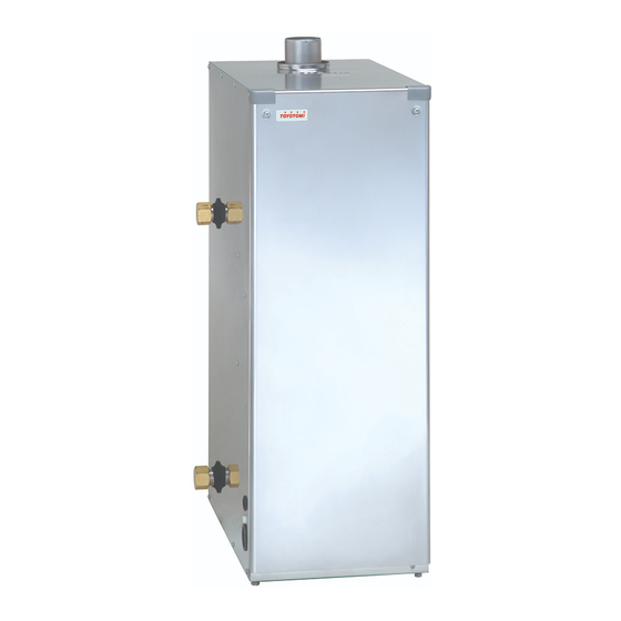
Kerosene-Fired Water Heater
Operation and Maintenance Instructions
MODEL FB-38N(FS)/FB-52N(FS)
IMPORTANT
READ AND UNDERSTAND INSTRUCTIONS BEFORE INSTALLING OR USING THIS WATER
HEATER. RETAIN INSTRUCTIONS FOR FUTURE REFERENCE. CHECK LOCAL CODES
AND ORDINANCES FOR PERMITTED USE.
CAUTION
THIS WATER HEATER SHALL NOT BE USED FOR COMMERCIAL USE OR ANY
PURPOSES OTHER THAN HOT WATER SUPPLY USES. OTHER USAGE MAY CAUSE A
MALFUNCTION OR SHORTEN ITS SERVICE LIFE.
PLATE AND LABELS FROM THE WATER HEATER UNIT.
Safety Tips..................................2
Safety Features...........................4
Specifications..............................5
Dimensional Outline....................6
Remote Control...........................7
Construction................................8
Fuel Guide.................................. 10
Fueling........................................ 11
Removing Air Trap...................... 11
DO NOT REMOVE THE RATING
[CONTENTS]
Inspection before Operation................ 11
Operation............................................ 12
Turning Unit Off.................................. 12
Adjusting Water Temperature.............. 12
Differential Switch and Dip Switch....... 13
Preventing Freeze Up.......................... 13
Long Term Inactivity............................ 13
Inspection and Maintenance................ 14
Inspection and Maintenance Items...... 14
Error Code in Display.......................... 17
Wiring Diagram................................... 18
1
Advertisement
Chapters
Table of Contents

Related Manuals for Toyotomi FB-38N


Summary of Contents for Toyotomi FB-38N
-
Page 1: Table Of Contents
Kerosene-Fired Water Heater Operation and Maintenance Instructions MODEL FB-38N(FS)/FB-52N(FS) IMPORTANT READ AND UNDERSTAND INSTRUCTIONS BEFORE INSTALLING OR USING THIS WATER HEATER. RETAIN INSTRUCTIONS FOR FUTURE REFERENCE. CHECK LOCAL CODES AND ORDINANCES FOR PERMITTED USE. CAUTION THIS WATER HEATER SHALL NOT BE USED FOR COMMERCIAL USE OR ANY PURPOSES OTHER THAN HOT WATER SUPPLY USES. -
Page 2: Section A
SECTION A: SAFETY TIPS BE SURE TO FOLLOW THE FOLLOWING INSTRUCTIONS. The instructions which are contained in this manual are classified into the following two types, which are “WARNING” and “CAUTION”. These instructions are intended to provide the important information for safe operation. “WARNING”... - Page 3 7. Insert the plug securely into the outlet as far as it will go. Do not use a damaged plug or loosened outlet. Do not remove or insert the plug with wet hands. 8. When you may not use it for a long period of time, turn off the operation switch, securely close the fuel feed valve of the fuel tank, and then remove the power cord plug from the outlet.
-
Page 4: Safety Features
SAFETY FEATURES NOTE: When a safety device is activated, the water heater is automatically extinguished. At this time, the error code is indicated on the digital display. When your water heater does not operate properly after you take remedies for the error correction, contact your dealer. -
Page 5: Section B
SECTION B: SPECIFICATIONS SPECIFICATIONS Model: FB-38N(FS) / FB-52N(FS) Type: - Combustion Type Pressure Vapor - Exhaust system Forced Exhaust type - Purpose Floor Heating Ignition: High Voltage Discharge Spark Fuel: Kerosene (Paraffin) Fuel Consumption: 4.2 L/h / 5.85 L/h Efficiency: 87.0%... -
Page 6: Dimensional Outline
DIMENSIONAL OUTLINE FB-38N(FS) - Page 7 FB-52N(FS)
-
Page 8: Remote Control
REMOTE CONTROL Power Lamp Power Switch Burner Lamp Temp Select Button (UP) External Input Lamp Display Temp Select Button (Down) POWER LAMP - constant: In operation - extinction: Shutdown BURNER LAMP - constant: In operation - extinction: Extinguished POWER SWITCH: Turns the unit on or off. -
Page 9: Construction
CONSTRUCTION FB-38N(FS) FB-52N(FS) -
Page 10: Section C
SECTION C: FUEL GUIDE The Water Heater is designed for use with water clean and high quality kerosene only. Use of low-quality kerosene will cause burner performance to drop, leading to abnormal combustion and reduced the unit life. Always store your fuel in a separate area from where you store gasoline for your power equipment to avoid accidental use of gasoline in your water heater. -
Page 11: Section D
SECTION D: OPERATION FUELING WARNING: Use KEROSENE only. Never use gasoline, thinner, benzene, light oil or waste oil. CAUTION: Make sure that the fuel is clean and free from dirt and water. Water and dirt may cause combustion failure and shorten the life of components such as the Fuel Pump. -
Page 12: Operation
OPERATION CAUTION: The excessive high temperature setting increases the risk of scald injury. (Thermal burn at low temperature) 1. Open the Fuel Tank Valve. 2. Press “POWER SWITCH” of Remote Controller. Opration lamp will come on and display indicates “7”. Automatic operation is based upon the temperature of water inside the heat exchanger. -
Page 13: Differential Switch And Dip Switch
DIFFERENTIAL SWITCH AND DIP SWITCH CAUTION: Please consult your dealer on the operation of DIP Switch. By the Differential Switch on the Main Circuit Board, the temperature of circulation water is controlled in the range of 2°C differential, 6°C differential, 9°C differential or 12°C differential. NOTE: If the wide differential is selected, the cycle frequency of ignition and extinguishments of the Burner will be reduced. -
Page 14: Section E
SECTION E: ROUTINE MAINTENANCE INSPECTION AND MAINTENANCE WARNING: RISK OF INJURY FROM MOVING PARTS AND ELECTRICAL SHOCK. Disconnect the Power Supply Cord before inspecting and servicing unit. repairs should be left to professionals. RISK OF BACKFIRE AND INDOOR POLLUTION. Before operation make sure the Exhaust Pipe is free of snow, icing, leaves, bird’s nest or strong drafts. - Page 15 9. PRESSURE RELIEF VALVE (ONCE A MONTH) The Pressure Relief Valve may become immovable at times due to corrosion of pipes or mineral deposits In the pipes. Pull up the lever of the Pressure Relief Valve every month and make sure the Valve is movable.
-
Page 16: Section F
SECTION F: TROUBLESHOOTING WARNING: RISK OF INJURY FROM MOVING PARTS AND ELECTRIC SHOCK. Disconnect the Power Supply Cord before servicing unit. All repairs should be left to professionals. Do not re-use the unit until the cause of the problems have been determined. CAUTION: RISK OF BURN INJURY. -
Page 17: Error Code In Display
ERROR CODE IN DISPLAY When the water heater is malfunctioned, the unit stops the operation automatically and Display indicates Error Code (“E” & “Number”) alternately by flashing. Display CAUSE RESULT E + 0 Disconnected model setting jumper terminal E + 2 Flame sensor detected flame before ignition E + 3 Disconnected thermistor... -
Page 18: Wiring Diagram
WIRING DIAGRAM Terminal Block for Model Selecting Remote Contorl Jumper Open Terminal Open Terminal Open Terminal Open Terminal Open Terminal Open Terminal Open Terminal Open Termin B: Blue O: Orange Y: Yellow W: White R: Red K: Black... - Page 19 TOYOTOMI CO., LTD. 5-17, MOMOZONO-CHO, MIZUHO-KU, NAGOYA, 467-0855 JAPAN New 9/08 Printed in Japan...
- Page 20 Kerosene-Fired Water Heater Installation Manual MODEL FB-38N(FS) / FB-52N(FS) IMPORTANT THIS APPLIANCE SHOULD BE INSTALLED BY A LICENSED, AUTHORIZED PERSON(S) DUE TO THE NECESSITY OF MAKING ELECTRICAL, WATER AND FUEL CONNECTIONS. RETAIN THIS MANUAL FOR FUTURE REFERENCE. CHECK LOCAL CODES AND ORDINANCES FOR PERMITTED USE.
-
Page 22: Section A
SECTION A: SAFETY TIPS FOR INSTALLATION BE SURE TO FOLLOW THE FOLLOWING INSTRUCTIONS. The instructions which are contained in this manual are classified into the following two types, which are “WARNING” and “CAUTION”. These instructions are intended to provide important information for safe operation. -
Page 23: Section B
SECTION B: UNPACKING UNPACKING 1. Unpack the unit carefully. 2. Check to see if there are any loose screws that may have occurred in transit. 3. Take accessories and the Operation and Maintenance instructions out of the carton. STANDARD INSTALLATION PARTS The following standard installation parts are enclosed with unit. -
Page 24: Level Adjustment
13. Select a place that can draw in sufficient air for combustion. The air intake hole should be placed in a spot can draw in outside air near the floor. [FB-38N(FS)] Effective hole area 450 cm... -
Page 25: Fuel Tank Installation
FUEL TANK INSTALLATION The fuel tank must be purchased separately and installed by a qualified fuel supply technician. NOTE: Fuel tank installation must comply with locally applicable codes. Check with local building officials. NOTE: Keep the fuel tank away from direct sunlight, high temperature, dust, rain and fire, and take preventive measures against falling during an earthquake. -
Page 26: Removing Air Trap
REMOVING AIR TRAP When operating for the first time or when refueling an empty Tank, air may be trapped in the Fuel Pipe, making ignition difficult. In this situation, follow the procedure below: 1. Turn the unit off by pressing “POWER SWITCH”. Disconnect the power supply cord. - Page 27 NOTE: Be sure to install the Pressure Relief Valve in the proper direction. CAUTION: Be sure to assemble the piping system at a pressure than 100 kPa because the maximum water pressure is 100 kPa. If not, the heat exchanber may be damaged.
- Page 28 SEMI-CLOSED / CLOSED EXPANSION TANK SELECTION NOTE: The Semi-closed Expansion Tank (optional) should be selected in accordance with the total water volume contained in the hot water piping system. NOTE: Refer to the formula below or the manufacturer’s formula when selecting the closed expansion tank.
- Page 29 WATER INJECTION AND AIR RELEASE FROM WATER HEATER PIPING (FOR CLOSED CIRCUIT PIPING) 1. Connect the water outlet of the floor cistern (selected by dealer) with the water inlet of the hot water pipe with a vinyl hose. 2. Connect the water inlet of the floor cistern with the city water outlet with a vinyl hose. 3.
- Page 30 WATER INJECTION AND AIR RELEASE FROM WATER HEATER PIPING (FOR SEMI-CLOSED CIRCUIT PIPING) SEMI-CLOSED CIRCUIT PIPING EXAMPLE 1. Antifreeze Solution specified by dealer should be used, and the density should be at a ratio of 40% to 50%, as shown in the table. Table of Antifreeze Solution composition ratio Freezing temp.
-
Page 31: Electrical Wiring
ELECTRICAL WIRING WARNING: RISK OF FIRE AND ELECTRIC SHOCK. Make sure the power supply cord is disconnected to avoid any electric shock before servicing. Electric shock may cause serious injury. It is recommended that installation should be conducted by a licensed electrician. - Page 32 For Installation on the wall 1. For installation with the double-sided adhesive tape (2 pcs.) included in the carton box Remove the screw on the Remote Controller Cover, and remove it from the base. (2) Attach the adhesive double-coated tape at the back of the base first, and then affix the base to the wall.
-
Page 33: Wiring For Water Heater
WIRING OF WATER HEATER (1) After making sure that the power supply cord is disconnected, remove the two (2) screws from the Rubber bushing front panel and remove the front panel. (2) Cut the rubber bushing on the left side panel by a cutter and insert the remote control cord. -
Page 34: Temperature Control (Differential Switch And Dip Switch)
TEMPERATURE CONTROL (DIFFERENTIAL SWITCH AND DIP SWITCH) NOE: Make sure that the power supply cord is disconnected when the position of DIP Switch is selected. 1. The differential switch on the main circuit board controls the heat exchanger water temperature. The switch can be set at a delta (on/off) of 2°C, 6°C, 9°C or 12°C. A higher delta reduces burner short cycling. -
Page 35: Section D
SECTION D: HOW TO INSTALL THE EXHAUST PIPE AND EXHAUST PIPE TOP WARNING: This unit is required to be installed the exhaust pipe and the exhaust pipe top. Make sure that Exhaust Pipe and Exhaust Pipe Top are properly connected. If it is disconnected, exhaust gas leak indoor during operation which may cause danger. - Page 36 local code concerning fire prevention. 10. Securing diagram of Exhaust Pipe and Exhaust Pipe Top installation NOTE: Put a semi-straight pipe or straight pipe in the Exhaust Pipe fitting hole at first, and lay transversely. NOTE: Select a place which is clear of combustible objects within 15 cm around the Exhaust Pipe Top, and 60 cm in the exhaust direction.
-
Page 37: Check For Exhaust Pipe And Exhaust Pipe Top
CHECK FOR EXHAUST PIPE AND EXHAUST PIPE TOP WARNING: Installation of Exhaust Pipe and Exhaust Top as shown below may cause an accident. Be sure to check once again after installation. Be sure to correct by following the installation presented below as an example in which a dangerous situation and incomplete combustion may occur. -
Page 40: Section E
SECTION E: TEST RUN PREPARATION 1. Make sure the exhaust pipe is installed properly. 2. Make sure the fuel tank is installed properly. Make sure there is no fuel leakage. 3. Make sure there is no water leaking from piping. (Plumbing) 4. - Page 41 TOYOTOMI CO., LTD. 5-17, MOMOZONO-CHO, MIZUHO-KU, NAGOYA, 467-0855 JAPAN New 9/08 Printed in Japan...