
Related Manuals for Motorola Starline SG 2000


Summary of Contents for Motorola Starline SG 2000
- Page 1 S T A R L I N E ® S G 2 0 0 0 T e l e c o m m u n i c a t i o n s O p t i c a l N o d e I n s t a l l a t i o n a n d O p e r a t i o n M a n u a l...
- Page 2 Motorola, Inc. Motorola, Inc. reserves the right to revise this publication and to make changes in content from time to time without obligation on the part Motorola, Inc. to provide notification of such revision or change. Motorola Inc. provides this guide without warranty of any kind, either implied or expressed, including, but not limited, to the implied warranties of merchantability and fitness for a particular purpose.
-
Page 3: Table Of Contents
C o n t e n t s S e c t i o n 1 I n t r o d u c t i o n Using this Manual ...1-3 Related Documentation ...1-3 Document Conventions ...1-4 If You Need Help ...1-4 Calling for Repairs...1-5 S e c t i o n 2 O v e r v i e w... - Page 4 Analog Return Path RF Configuration ...5-5 Digital Return Path RF Configuration ...5-7 SG 2000 Optical Modules ...5-9 Installing SG 2000 Optical Modules ... 5-9 Removing SG 2000 Optical Modules ... 5-9 Cleaning the Optical Connector... 5-10 SG2-LR Optical Receiver ... 5-10 Wavelength Selection Jumper ...
- Page 5 Figure 1-1 SG 2000 — closed ... 1-1 Figure 1-2 SG 2000 — open ... 1-2 Figure 2-1 SG 2000 housing dimensions - front and side view ... 2-1 Figure 2-2 Port locations ... 2-2 Figure 2-3 Housing gaskets ... 2-3 Figure 2-4 SG2-PS2 power supply ...
- Page 6 C o n t e n t s Figure 3-6 JP1 common-powered single or redundant power configuration ... 3-7 Figure 3-7 JP1 split-powered redundant power supply configuration ... 3-7 Figure 3-8 SG2-75 low-gain output-stage pad-effects chart ... 3-14 Figure 3-9 SG2-87 low-gain output-stage pad-effects chart ... 3-15 Figure 3-10 SG2-* link c/n performance, 77 channels ...
- Page 7 Figure 5-23 DS-SG2-DRT-2X/A... 5-22 Figure 5-24 DS-SG2-DRT-2X/A... 5-22 Figure 5-25 DS-SG2-DRT-2X/A cable connector ... 5-24 Figure 5-26 DS-SG2-DRT-2X/A installed in SG 2000 ... 5-24 Figure 5-27 DS-SG2-DRT-2X/A second RF input cable connection ... 5-25 Figure 5-28 SG2-PS power supply ... 5-25 Figure 5-29 MCB board ...
- Page 8 C o n t e n t s Table A-13 Current requirements ... A-7 Table A-14 SG2-75 performance, with 77 channels ... A-8 Table A-15 SG2-87 performance, with 94 channels ... A-8 Table A-16 SG2-87 performance, with 110 channels ... A-8 S G 2 0 0 0 I n s t a l l a t i o n a n d O p e r a t i o n M a n u a l...
- Page 9 Se ction 1 I n t r o d u c t i o n Motorola’s SG 2000 telecommunications optical node performs light wave-to-RF and RF-to-light wave signal conversions in an optical transmission link. This product is designed to support a wide variety of advanced hybrid-fiber/coaxial network topologies.
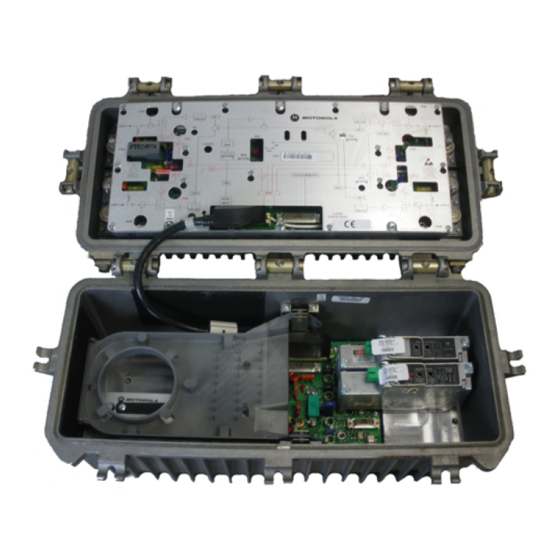
- Page 10 1 - 2 I n t r o d u c t i o n Figure 1-2 illustrates an open SG 2000 telecommunications optical node: F i g u r e 1- 2 SG 2 0 00 — o p en...
-
Page 11: I N T R O D U C T I O N
Section 2 Overview describes the SG 2000 node and includes details regarding your options and their functions. Section 3 Bench Setup provides full configuration, set-up of options, and bench testing procedures that are recommended before installation. -
Page 12: Document Conventions
I n t r o d u c t i o n D o c u m e n t C o n v e n t i o n s Before you begin to use the SG 2000, familiarize yourself with the stylistic conventions used in this manual:... -
Page 13: Calling For Repairs
C a l l i n g f o r R e p a i r s If repair is necessary, call the Motorola Repair Facility at 1-800-642-0442 for a Return for Service Authorization (RSA) number before sending the unit. The RSA number must be prominently displayed on all equipment cartons. -
Page 14: O V E R V I E W
Se ction 2 O v e r v i e w Designed to be flexible, you can configure the SG 2000 with up to three optical receivers, four independent high-level RF outputs, and two return-path optical transmitters. Multiple receiver and transmitter combinations are available to satisfy split-band or redundancy requirements. -
Page 15: Port Locations
2 - 2 O v e r v i e w Port Locations The five housing ports, shown in Figure 2-2, provide connection for coaxial cables. Note that the housing ports are not labeled the same as the ports on the RF chassis. Side-by-side connector fittings are limited to .750 inches at ports 1 and 2 and/or ports 3 and 4. -
Page 16: Gaskets
FWD EQ FWD EQ JXP 2 +24 V DC VARILO SSER SG2- STATUS MONITOR RPM/* JXP 3 SG 2000 JXP 4 RCVR Optical Node INPUT FWD EQ FWD EQ RF gasket (woven wire) S G 2 0 0 0 I n s t a l l a t i o n a n d O p e r a t i o n M a n u a l... -
Page 17: Power Supply
Figure 3-2 illustrates the location of the fuses. The SG 2000 optical node can be powered from either 60 Vac or 90 Vac system power supplies. The unit is shipped from the factory set for 60 Vac powering. For systems equipped with 90 Vac powering, the suitcase jumper on the dc power supply can be repositioned to optimize the supply start-up voltage for the higher input range. -
Page 18: Network Monitoring
C o n f i g u r a t i o n To accommodate unique system criteria, the SG 2000 is shipped as a configured product. Hundreds of variations are available with configurations designed to address numerous system requirements... -
Page 19: Figure 2-5 Configuration Notation
O v e r v i e w You can order the SG 2000 in a number of configurations to suit system requirements. The shipped configuration is noted in a label on the lower portion of the RF chassis cover. -
Page 20: Forward Path
Automatic path switchover occurs through either the optional status monitoring or manual control-board modules. Figure 2-6 provides a diagram of the signal flow-path through the SG 2000: F i g u r e 2- 6... - Page 21 Several plug-in boards are available to configure the SG 2000 lid board for single, redundant, or narrowcast receiver arrangements. A low-noise pre-amplifier hybrid amplifies the signal to a level suitable for connection to the RF chassis.
-
Page 22: Sg2-Lr Receiver
SG2-LR Receiver The receiver module (SG2-LR) is designed specifically for high performance in the SG 2000. The SG2-LR receiver uses an integrated optical-hybrid photo-detector for improved RF performance over the entire 40 MHz through 870 MHz passband. It is enabled and disabled in response to a signal from the status monitor transponder or manual control board (MCB). -
Page 23: Analog Return Path
2 - 1 0 O v e r v i e w A n a l o g R e t u r n P a t h Similar to the multiple optical receivers, the dual return-path optical transmitters also have split-return or redundant functionality. -
Page 24: Figure 2-8 Sg2 Transmitter Block Diagram
Figure 2-8 illustrates a functional block diagram of the SG2 transmitter: F i g u r e 2- 8 SG 2 t r an sm it t e r bl oc k d i ag ra m Thermal input compensation O v e r v i e w Hybrid current... -
Page 25: Digital Return Path
2 - 1 2 O v e r v i e w D i g i t a l R e t u r n P a t h The digital return transmitter series (DS-SG2-DRT*) converts a broadband analog RF return-path signal into digital optical signals with 10-bit resolution. -
Page 26: Ds-Sg2-Drt-2X/A
O v e r v i e w 2 - 1 3 When configured for redundancy, both return transmitters are normally active and transmit the combined RF return signal simultaneously. In the event of path failure, continuity of service is accomplished at the headend or the receiver site by switching to the alternate or active return fiber. -
Page 27: Level Control
O p t i o n s a n d A c c e s s o r i e s Table 2-3 provides a list of options and accessories for the SG 2000: T able 2- 3... - Page 28 Model Description SG2-MCB Manual control board SG2-SB/* Strand bracket SG2-PS Power supply SG2-PS2 Power supply SG2- Service cable SERCAB/* SG2-FE- Forward */750 equalizers SG2-FE- Forward */870 equalizers SG2-IS Ingress switch SG2-LR Lightwave receiver DS-SG2-DRRB Digital return redundancy board SG2-* Analog return transmitters DS-SG2-DRT* Digital return transmitters...
-
Page 29: Gain Selection
O v e r v i e w Gain Selection Figures 2-9 through 2-13 illustrate SG 2000 gain and tilt selection charts based on frequency and channel load options. To use the gain option selection charts, Figures 2-9 and 2-10, first find the point on the left hand axis that corresponds to the expected optical input power at the node. -
Page 30: Figure 2-10 Optical Input Versus 870 Mhz Gain
Figure 2-10 illustrates the gain option selection chart for 870 MHz: F i g u r e 2- 10 O p t i ca l inp ut v e r su s 87 0 M Hz ga in Bridger output level (dBmV), 870 MHz equivalent Lo gain limit, 110 ch Hi gain limit, 110 ch Lo gain limit, 94 ch... -
Page 31: Tilt Selection
2 - 1 8 O v e r v i e w Tilt Selection To use the tilt selection charts, first determine the system operating bandwidth, either 750 MHz or 870 MHz. Next, determine the desired system channel load either 77, 94, or 110 channels. Use the corresponding bandwidth and channel loading chart to determine the preferred tilt, either low, standard, or high. - Page 32 Figure 2-12 illustrates the tilt selection chart for 870 MHz bandwidth and 94-channel load: F i g u r e 2- 12 Re lat iv e l ev e l dB v e r su s 87 0 M Hz s lop e 9 4 ch ann el s High Standard SG2 870 MHz Slope Chart...
- Page 33 2 - 2 0 O v e r v i e w Figure 2-13 illustrates the tilt selection chart for 870 MHz bandwidth and 110-channel load: F i g u r e 2- 13 Re lat iv e l ev e l dB v e r su s 87 0 M Hz s lop e 1 10 cha nn el s High Standard S G 2 0 0 0 I n s t a l l a t i o n a n d O p e r a t i o n M a n u a l...
-
Page 34: B E N C H S E T U P
B e n c h S e t u p Before you install the SG 2000 you must set it up to meet the power and configuration requirements for the node location. Bench set-up and quick check procedures are recommended to ensure proper functioning of all components and simplify field installation. - Page 35 3 - 2 B e n c h S e t u p Figure 3-2 illustrates the RF chassis with the cover removed indicating the location of major components: Figu r e 3- 2 SG 2 0 00 R F ch as s is Drive unit selector (AUTO/MAN) Gain control (MAN ADJ) Driver hybrid...
- Page 36 P o w e r i n g t h e N o d e You can conveniently power the SG 2000 by applying 60 Vac or 90 Vac to housing port 2. This port is not used for RF purposes. All ports are rated at 15 amperes maximum and are fused with common, blade-type 20-ampere automotive fuses.
-
Page 37: Table 3-1 Ac Fuses
3 - 4 B e n c h S e t u p Table 3-1 identifies and describes the ac fuse options: T able 3- 1 AC f u se s Fuse Function This fuse delivers ac power to all ports. It is always required except when power from the ac input (port 2) must be blocked at this location. - Page 38 P o w e r S u p p l y S e t t i n g s You can power the SG 2000 from either 60 Vac or 90 Vac system supplies. The unit is shipped from the factory set for 60 Vac ( ).
-
Page 39: Figure 3-5 Sg2-Ps2 Power Supply
SEE INSTALLATION MANUAL FOR SERVICE A second, optional dc power supply located in the lid of the SG 2000, offers full redundancy. Both power supplies are on-line continuously and share the current load. In the event one supply fails, the other assumes the entire load with no disruption of service. -
Page 40: Single Power Supply Or Commonly Powered Redundant Supplies
Single Power Supply or Commonly Powered Redundant Supplies To activate a single power supply or commonly powered redundant supplies, place jumper JP1 (illustrated in Figure 3-1) on the SG2-LIDB in the vertical position (strand-mount installation). Figure 3-6 illustrates this position. Power supplies #1 and #2 are both connected to the primary ac power feed. -
Page 41: Quick Checks - Functional Testing
Q u i c k C h e c k s - F u n c t i o n a l T e s t i n g It is recommended that you perform the procedures presented in the following subsections before you place the SG 2000 in service. Forward Path Figure 3-1 illustrates the location of the forward-path receiver modules. -
Page 42: Manual Gain Control
Remeasure the output level. It should be within 1 dB of the preferred level. If necessary, adjust the manual gain control. Check the remaining ports and add JXP pads to bring the outputs to the correct level. Set the gain reserves using one of the following gain control options. Adjust the selected gain control option using the procedure presented in the appropriate subsection below. -
Page 43: Analog Return Path
With the SG 2000 return path module/combined (SG2-RPM/C), the total combined power at all four ports totals approximately +28 dBmV. With the SG 2000 return path module/split (SG2-RPM/S), the total combined power at each pair of ports is approximately +28 dBmV. -
Page 44: Forward Path Padding
B e n c h S e t u p 3 - 1 1 F o r w a r d P a t h P a d d i n g The pad values, presented in Table 3-2 or Table 3-3, serve as a starting-point reference for typical installations. -
Page 45: Table 3-2 Sg 2000 Pad Chart-Standard Gain
3 - 1 2 B e n c h S e t u p T able 3- 2 SG 2 0 00 p ad ch a rt - st and a rd ga in I n p u t d B m / m W 2.0/1.6 Receiver JXPs Common JXP... -
Page 46: Table 3-3 Sg 2000 Pad Chart-High Gain
T able 3- 3 SG 2 0 00 p ad ch a rt - h i gh g ai n I n p u t d B m / m W 2.0/1.6 Receiver JXPs Common JXP Output JXPs 1.5/1.4 Receiver JXPs Common JXP Output JXPs 1.0/1.3... -
Page 47: Launch Amplifier Output Stage Padding
3 - 1 4 B e n c h S e t u p L a u n c h A m p l i f i e r O u t p u t S t a g e P a d d i n g By definition the launch amplifier is everything between the optical receiver RF output and the node output connector. -
Page 48: Link Performance
L i n k P e r f o r m a n c e The SG 2000-* link performance charts are meant as a guide to assist you when working with varying link parameters. The link is defined as beginning at the transmitter RF input and ending at the RF output jack on the SG2-LR optical receiver. -
Page 49: Figure 3-10 Sg2-* Link C/N Performance, 77 Channels
3 - 1 6 B e n c h S e t u p Figu r e 3- 10 SG 2- * lin k c /n pe rf o r man c e, 7 7 ch an ne l s S G 2 0 0 0 I n s t a l l a t i o n a n d O p e r a t i o n M a n u a l Received optical power, dBm Lf = fiber loss budget... -
Page 50: Figure 3-11 Sg2-* Link C/N Performance, 110 Channels
Figu r e 3- 11 SG 2- * lin k c /n pe rf o r man c e, 1 1 0 ch ann e ls Received optical power, dBm Lf = fiber loss budget S G 2 0 0 0 I n s t a l l a t i o n a n d O p e r a t i o n M a n u a l B e n c h S e t u p 3 - 1 7 -64.5... -
Page 51: Installing The Ds-Sg2-Drrb Board Option
3 - 1 8 B e n c h S e t u p I n s t a l l i n g t h e D S - S G 2 - D R R B B o a r d O p t i o n The SG2 Digital Return Redundancy Board (DS-SG2-DRRB) is a fixed plug-in that only provides the capability for RF redundancy to the input of the (DS-SG2-DRT-2X/A). - Page 52 Figu r e 3- 13 DS -S G2- DR RB bo a rd ins t a ll ed Insert the MCX connector terminating cable J1 into transmitter A location. Insert the MCX connector terminating cable J2 into transmitter B location. Remove the existing 0 dB jumpers and install 1 dB JXPs in the four return-path JXP locations on the E-pack as illustrated in Figure 3-14.
-
Page 53: Figure 3-14 Location Of Jxps On E-Pack
3 - 2 0 B e n c h S e t u p Figu r e 3- 14 L o c at i on of J X Ps on E- p a ck Replace 0 dB JXP with 1 dB JXP Replace 0 dB JXP with 1 dB JXP S G 2 0 0 0 I n s t a l l a t i o n a n d O p e r a t i o n M a n u a l... -
Page 54: Figure 3-15 Sg2 Lid Configured With The Ds-Sg2-Drrb Board
Figure 3-15 illustrates a complete SG2 lid with the DS-SG2-DRRB board (shaded gray) installed: Figu r e 3- 15 SG 2 lid conf igu r ed w it h t he D S- SG 2- DR RB bo ar d When signals are applied to port in and port 1, they are routed directly to the transmitters through the D-type connectors on the lid board. -
Page 55: Installing The Status Monitor Option
3 - 2 2 B e n c h S e t u p I n s t a l l i n g t h e S t a t u s M o n i t o r O p t i o n The model LL-SG2-*/* transponder is available as part of the LIFELINE status-monitoring system. -
Page 56: Sg 2000 Activation Worksheet
S G 2 0 0 0 A c t i v a t i o n W o r k s h e e t This worksheet is provided as a convenient reference to log pertinent information associated with setting up the SG 2000 node. Configurator... - Page 57 3 - 2 4 B e n c h S e t u p DC powering Is the suitcase jumper on the power pack(s) in the correct position? _____60 V (lo) _____90 V (hi) Is the round, green LED on the main board illuminated? _____ yes _____ no Are the two rectangular green LEDs on each power pack illuminated? _____ 24 Vdc _____ 5 Vdc Voltage reading at 24 Vdc test point? _____ Vdc Voltage reading at 5 Vdc test point? _____ Vdc...
-
Page 58: I N S T A L L A T I O N
Se ction 4 I n s t a l l a t i o n Installation consists of splicing the six-fiber service cable to the transportation fiber, installing the housing and electronics on the messenger strand, applying power, and placing the unit in service. To avoid excess weight and the possibility of damage during installation, the housing is normally mounted prior to inclusion of the electronic components. - Page 59 4 - 2 I n s t a l l a t i o n Assemble the splice enclosure following the instructions furnished with the enclosure. CA UT ION! It is important that the connections at the headend be duplicated. If they are different from the above recommendations, follow the scheme used for the headend connections.
-
Page 60: Strand Wire Mounting
I n s t a l l a t i o n 4 - 3 S t r a n d W i r e M o u n t i n g Two strand clamps and bolt assemblies are located on a bracket attached to the top of the housing for normal horizontal mounting below the strand. -
Page 61: Figure 4-3 Mounting Bracket-Rear And Side Views
4 - 4 I n s t a l l a t i o n F i g u r e 4- 3 M ounting b r ac k et- re a r and sid e v iew s To mount the housing to the strand wire: Attach the bracket to the housing using the two 5/16 ×... -
Page 62: Coaxial Cables
Figure 4-4 illustrates the dimensions of the center conductor: F i g u r e 4- 4 Cen t e r co ndu ct o r l en gt h There are no surge protectors over the center seizure screws and none should be installed. Adding surge protectors degrades the return loss of the housing port. -
Page 63: Figure 4-5 Housing Lid And Fiber Spool Tray
4 - 6 I n s t a l l a t i o n Carefully dress the excess fiber into the ramp of the fiber spool tray. Wrap the fiber around the spooling cylinder one to two times depending on the length of the fiber. The diameter of the spool tray is matched to the bend radius of the fiber. - Page 64 Connect each fiber by removing the protective boot from the fiber connector, cleaning the connector with pure isopropyl alcohol (99%) using a lint-free wipe, and drying it with filtered compressed air. After cleaning the fiber, insert it into the appropriate receiver or transmitter module.
-
Page 65: O P E R A T I O N
It may be helpful to refer to Figures 3-1 and 3-2 that illustrate the major components in the SG 2000 lid and RF chassis. F o r w a r d P a t h R F C o n f i g u r a t i o n You can configure the SG2-lid motherboard (LIDB) using three different forward path RF options. -
Page 66: Redundant Receiver Mode
5 - 2 O p e r a t i o n Redundant Receiver Mode Operation in the redundant mode requires the installation of two optical receivers, one in position A and the other in position B. An SG2-ABJ/P jumper board must be plugged into the lid motherboard. Figure 3-1 illustrates the location of this jumper board. -
Page 67: Ab Override Functionality
O p e r a t i o n 5 - 3 AB Override Functionality The AB override switch (jumper JP2, illustrated in Figure 3-1) can be operated in three different positions. The positions are B override, A override, and status monitor/MCB: B Override The SG2-LIDB overrides the status monitor or manual control board signal and activates receiver B, as illustrated in Figure 5-4:... -
Page 68: A Override
5 - 4 O p e r a t i o n A Override The SG2-LIDB overrides the status monitor or manual control board signal and activates receiver A as illustrated in Figure 5-5: F i g u r e 5- 5 A o v er r id e Status monitor signal... -
Page 69: Analog Return Path Rf Configuration
A n a l o g R e t u r n P a t h R F C o n f i g u r a t i o n If you are using a single optical transmitter, it must be installed in the optical transmitter A position as illustrated in Figure 3-1. - Page 70 5 - 6 O p e r a t i o n For upgrading to split return operation, with DS-SG2-DRT-2X/A transmitters installed in positions A and B, the SG2-RPM/C board must be replaced with an SG2-RPM/S board. The main RF chassis must be removed to perform this exchange.
-
Page 71: Digital Return Path Rf Configuration
Remove the eight screws that secure the SG2-RPM/C board to the chassis. Remove the SG2-RPM/C board. To assist in removing the SG2-RPM/C board, the handle is cantilevered so that pulling up on the handle extracts the board from the chassis. Remove the 5-pin power connector that provided dc power to the SG2-RPM/C board. - Page 72 5 - 8 O p e r a t i o n If you are using a single DS-SG2-DRT-2X/A transmitter, it must be installed in the optical transmitter A position. A JXP-5A (5 dB) pad must be installed in the pad facility at the input of both the A and B transmitter locations.
-
Page 73: Sg 2000 Optical Modules
Installing SG 2000 Optical Modules The design of the SG 2000 optical modules enable you to install them while the node is in service. To install an optical module: Determine the proper slot for the module by referring to the Forward Path RF Configuration or the Return Path RF Configuration information in the beginning of this section. -
Page 74: Cleaning The Optical Connector
S G 2 - L R O p t i c a l R e c e i v e r The SG2-LR is a line of forward-path optical receivers used in the SG 2000 node platform. It is designed to be used in conjunction with an AM-Blazer, AM-OMNI-LM*, MegaStar, or other similar optical transmitter. -
Page 75: Table 5-1 Sg2-Lr Features
Tables 5-1 and 5-2 provide additional information on the user-related features and output levels of the SG2-LR: T ab le 5- 1 SG 2- L R f e at u re s Feature Optical power test point Hybrid current test point Receiver enable Fault indicator Optical power status... - Page 76 5 - 1 2 O p e r a t i o n O p t i c a l i n p u t T P V o l t s l e ve l ( d B m / m W ) ( 1 m W = 1 V ) –2.0/0.6 –2.5/0.6...
-
Page 77: Wavelength Selection Jumper
W a v e l e n g t h S e l e c t i o n J u m p e r The SG2-LR can be used with either 1310 nm or 1550 nm transmitters. An internal wavelength selection jumper optimizes the optical power test point and optical power status indicator calibration for the system wavelength. -
Page 78: Sg2-Ifpt Optical Transmitter
The SG2-IFPT is an isolated Fabry-Perot return-path optical transmitter designed for use in the SG 2000 node platform. It has a nominal optical output power of 0.4 mW and can be used in conjunction with an AM-RPR, AM-OMNI-RPR/2, or other similar return path optical receiver. -
Page 79: Sg2-Fpt Optical Transmitter
Feature Description Transmitter enable A green LED that provides visual indication of the transmitter’s enable status. Fault indicator A single red LED that lights when the hybrid current is outside the normal operating range, the laser output power is below normal limits, or the laser current is above normal limits. -
Page 80: Sg2-Dfbt Optical Transmitter
The SG2-DFBT is an isolated distributed feedback (DFB) return path optical transmitter used in the SG 2000 node platform. It has a nominal optical output power of 1.0 mW and is used in conjunction with an AM-RPR, AM-OMNI-RPR/2, or other similar return-path optical receiver. - Page 81 Feature Description Transmitter enable A green LED that provides visual indication of the transmitter’s enable status. Fault indicator A single red LED that lights if the hybrid current is outside the normal operating range, the laser output power is below normal limits, or the laser current is above normal limits.
-
Page 82: Figure 5-19 Sg2-Dfbt/3
The SG2-DFBT/3 is an isolated distributed feedback (DFB) return path optical transmitter used in the SG 2000 node platform. It has a nominal optical output power of 2.0 mW and is used in conjunction with an AM-RPR, AM-OMNI-RPR/2, or other similar return-path optical receiver. -
Page 83: Figure 5-20 Sg2-Eifpt
The SG2-EIFPT is an enhanced, isolated, Fabry-Perot return-path optical transmitter designed for use in the SG 2000 node platform. It has a nominal optical output power of 1 mW and can be used in conjunction with an AM-RPR, AM-OMNI-RPR/2, or other similar return path optical receiver. - Page 84 5 - 2 0 O p e r a t i o n D S - S G 2 - D R T / A D i g i t a l R e t u r n T r a n s m i t t e r The DS-SG2-DRT/A is an SG2 return transmitter that digitizes a single analog 5 MHz-42 MHz return-path signal to produce a 1.6 Gbps data stream.
- Page 85 Table 5-8 provides information on the user-related features of the DS-SG2-DRT/A transmitters: T ab le 5- 8 DS -S G2- DRT / A f e atu r es Feature Test point A Input A Increment attenuator setting Decrement attenuator setting Change increment/ decrement direction Restore factory default...
- Page 86 5 - 2 2 O p e r a t i o n D S - S G 2 - D R T - 2 X / A D i g i t a l R e t u r n T r a n s m i t t e r The DS-SG2-DRT-2X/A is an SG2 return transmitter that digitizes two independent analog 5 MHz-42 MHz return-path signals to produce two 1.25 Gbps data streams.
- Page 87 Table 5-9 provides information on the user-related features of the DS-SG2-DRT-2X/A: T ab le 5- 9 DS -S G2- DRT -2 X / A f e atu re s Feature Test point A and B Input A and B ncrement attenuator setting Decrement attenuator setting...
- Page 88 F i g u r e 5- 25 D S - S G 2- D R T - 2 X / A c a bl e co n n e ct o r Figure 5-26 illustrates the DS-SG2-DRT-2X/A installed in the SG 2000 with completed fiber connections:...
-
Page 89: Sg2-Ps Power Supply
Figure 5-27 provides greater detail of the DS-SG2-DRT-2X/A second RF input cable connection to the LIDB. This cable connects the other half of the split return to the DS-SG2-DRT-2X/A. F i g u r e 5- 27 D S - S G 2- D R T - 2 X / A s e co n d R F i n p u t ca b l e co n n e ct i o n Second RF input cable SG2-PS Power Supply... - Page 90 O p e r a t i o n S t a t u s M o n i t o r i n g Table 5-10 identifies and describes the status monitor provisions built into the SG 2000 platform: T able 5- 1 0...
-
Page 91: Manual Control Board
M a n u a l C o n t r o l B o a r d The SG 2000 manual control board (SG2-MCB) serves to locally control redundancy functions and ingress switch operation if a status monitor is not installed. Figure 3-2 illustrates the MCB board mounted on the main RF board in place of the status monitor. -
Page 92: Figure 5-29 Mcb Board
5 - 2 8 O p e r a t i o n Description Function Alarm test point ) provides access for measuring the cross-over optical level ALRM TP threshold. 3 dB test point (3 dB ) is used to measure the optical power of the primary receiver. Measurements at this test point are 3 dB less than the actual value. -
Page 93: Status Monitoring
I n g r e s s C o n t r o l The SG 2000 platform incorporates electronic ingress control switching enabling operators to choose one of three options for troubleshooting noise sources. A maximum of four switches, (one ingress switch per RF port) can populate the RF amplifier. - Page 94 S p e c i f i c a t i o n s Specifications for the SG 2000 are valid over the given bandpass and operating temperature range listed in this section. The current catalog may contain additional information not provided below.
- Page 95 Parameter Flatness over passband Operational tilt (standard) Table A-3 lists the general characteristics for the SG 2000 node: T able A- 3 SG 2 0 00 G en er al ch a ra ct e ri st i c s...
- Page 96 Table A-5 lists the RF performance specifications for the SG2-IFPT laser transmitter: T ab le A- 5 SG 2- I F PT RF sp e cif i c at i on s Parameter Nominal RF input impedance RF passband Flatness (peak to valley) RF input return loss Recommended total input power...
- Page 97 A - 4 S p e c i f i c a t i o n s Table A-7 lists the RF performance specifications for the SG2-DFBT laser transmitter: T able A- 7 SG 2- D FBT R F sp ec if i cat ion s Parameter Nominal RF input impedance RF passband...
- Page 98 Table A-9 lists the RF performance specifications for the SG2-EIFPT laser transmitter: T ab le A- 9 SG 2- EI FPT RF sp e cif i cat ion s Parameter Nominal RF input impedance RF input passband Flatness (peak to valley) RF input return loss Recommended total input power...
- Page 99 A - 6 S p e c i f i c a t i o n s Table A-11 lists the RF performance specifications for the SG2-DRT-2X/A digital return transmitter: T able A- 1 1 SG 2- D RT - 2 X/ A R F sp ec if i c at i on s Parameter Specification Nominal RF input...
- Page 100 Table A-13 lists the current requirements for various options and the two platforms available in the SG 2000: T ab le A- 1 3 Cu rr ent req ui r em ent s Option Basic- platform (one-way, single receiver: Note 1)
- Page 101 A - 8 S p e c i f i c a t i o n s Table A-14 lists distortion and c/n performance for the SG2-75 with a load of 77 channels: T able A- 1 4 SG 2- 75 p erf or m an ce , w it h 77 c h a n n el s 77 Channels Link Launch...
- Page 102 Append ix B To r q u e S p e c i f i c a t i o n s Torque specifications are valid for all models of the SG 2000 node. Fastener Screw Size Strand clamp/pedestal 5/16-18...
- Page 103 A b b r e v i a t i o n s a n d A c r o n y m s The abbreviations and acronyms list contains the full spelling of the short forms used in this manual. ampere alternating current analog-to-digital...
- Page 104 A b b r e v i a t i o n s a n d A c r o n y m s - 2 NTSC National Television Standards Committee optical modulation index Peak-to-valley picoampere radio frequency relative intensity noise return for service authorization snap connector thermal control unit...
- Page 105 481740-001 12/01 MGBI...