GE JES2251SJ Technical Service Manual
Hide thumbs
Also See for JES2251SJ:
- Datasheet (2 pages) ,
- Datasheet (2 pages) ,
- Owner's manual (24 pages)

Related Manuals for GE JES2251SJ


Summary of Contents for GE JES2251SJ
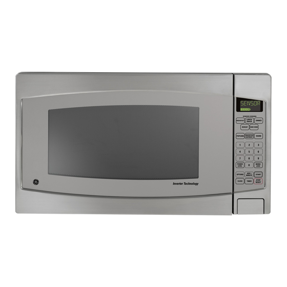
- Page 1 GE Consumer Products TECHNICAL SERVICE GUIDE Microwave Oven MODEL SERIES: JES2251SJ PUB # 31-9129...
- Page 2 If grounding wires, screws, straps, clips, nuts, or washers used to complete a path to ground are removed for service, they must be returned to their original position and properly fastened. GE Consumer Products Technical Service Guide Copyright © 2004 All rights reserved.
- Page 3 DANGER OF HIGH VOLTAGE AND HIGH TEMPERATURE (HOT/LIVE) OF THE INVERTER POWER SUPPLY (U) INVERTER WARNING This inverter board looks like a regular PCB. However, this PCB drives the magnetron tube with NEW H.V. extremely high voltage and high current. IT HAS: 1.
-
Page 4: Table Of Contents
Specifications: Models: JES2251SJ Specifications: Power Source: 120V AC Single Phase, 60Hz Power Requirement: 1500W Output: 1200W Microwave Frequency: 2450MHz Timer: 30 min. / Stage (HIGH Power) ~ 5 Stage Maximum 99 min. 99 sec. / Stage (Other Power Levels) ~ 5 Stage Maximum Outside Dimensions: ”(606mm)(W) x 19... -
Page 5: Feature Chart
1 FEATURE CHART MODEL JES2251SJ FEATURE Five Stage Cooking Inverter Defrost Popcorn Sensor Cooking Sensor Reheat More/Less Timer Digital Clock Child Safety Look Add 1 Minute 2 CONTROL PANEL Display Window Sensor Cooking Pads Inverter Defrost Pad Popcorn Pad Warm Pad... -
Page 6: Operation And Digital Programmer Circuit Test Procedure
3 OPERATION AND DIGITAL PROGRAMMER CIRCUIT TEST PROCEDURE 3.1. To set clock 3.3. Inverter defrost OPERATION! SCROLL DISPLAY OPERATION! SCROLL DISPLAY 1. Plug the power supply 1. Press INVERTER TURBO cord into wall outlet. Inverter Defrost Pad. DEFROST 2. Press Clock pad. 2. -
Page 7: Sensor Cooking
3.5. Warm 3.7 To set/reset child safety lock OPERATION! SCROLL DISPLAY OPERATION! SCROLL DISPLAY 1. Press Warm pad. K E E P WA R M 1. Press Options pad. SELECT FUNCTION 2. Press Number pad to CHILD LOCK ON/OFF 2. Set for 1 minute by select 5. -
Page 8: Schematic Diagram
4 SCHEMATIC DIAGRAM (DC 4000V) (PULSE 5V) -
Page 9: Description Of Operating Sequence
5 DESCRIPTION OF OPERATING SEQUENCE 5.1. Variable power cooking control 5. Output power of the magnetron tube is always monitored by the signal output from the current High Voltage Inverter Power Supply (U) controls transformer built into the inverter circuit. output power by the signal from Digital Programmer 6. - Page 10 T2 = T1 X K AUTO SENSOR COOKING/REHEAT PROCESS = 2 min. and 40 sec. X 0.2 = 160sec. X 0.2 = 32 sec. K Factor Category Power Power Standard Oatmeal HIGH HIGH 5.5. Sensor reheat Auto Sensor Reheat is a quick and easy way to reheat refrigerated and room temperature foods.
-
Page 11: Cautions To Be Observed When Troubleshooting
6 CAUTIONS TO BE OBSERVED WHEN TROUBLESHOOTING Unlike many other appliances, the microwave oven H.V. Inverter warning is a high voltage, high current device. It is free from WARNING FOR INVERTER POWER SUPPLY (U) danger in ordinary use, though extreme care should GROUNDING be taken during repair. -
Page 12: Confirm After Repair
2. When replacing the fuse, confirm that it has the appropriate rating for these models. 3. When replacing faulty switches, be sure the mounting tabs are not bent, broken or deficient in their ability to hold the switches. 6.5. Avoid inserting nails, wire etc. through any holes in the unit during operation. -
Page 13: Disassembly And Parts Replacement Procedure
7 DISASSEMBLY AND PARTS REPLACEMENT PROCEDURE 7.1. Magnetron 7.2. Digital programmer circuit (D.P.C) NOTE: 1. Discharge high voltage charge. Before handing the D.P.C ensure that your 2. Remove 2 screws holding air guide A on the oven body is connected to ground to discharge any cavity. - Page 14 7.3. Low voltage transformer and/or 7.5. Door assembly power relays (RY1, RY2) 1. Remove door C from door E by carefully pulling outward, starting from upper right hand corner NOTE: using a flat blade screwdriver. Be sure to ground any static electric charge built 2.
- Page 15 7.6. Turntable motor 7.7. Steam sensor 1. Remove the motor cover by cutting, at the locations 1. D i s c o n n e c t c o n n e c t o r C N 2 f r o m d i g i t a l indicated by the arrows, with a cutter.
- Page 16 7.8. Inverter power supply 6. Press 1 encircled locking tab and then slide 4 locking tabs of Inverter bracket at the bottom of the base in direction of arrows. CAUTIONS 1.Always leave the grounding plate in place. 2.Always securely tighten the ground screw through the bottom of the chassis (base).
-
Page 17: Component Test Procedure
8 COMPONENT TEST PROCEDURE CAUTIONS NEW. H.V. 1.High voltage is present at the high voltage 8.3. Magnetron terminal of the High Voltage Inverter (U) Continuity checks can only indicate an open filament including aluminum heat sink during any cook or a shorted magnetron. To diagnose for an open cycle. - Page 18 8.5. Inverter power supply (U) DO NOT try to repair H.V. Inverter Power Supply (U). a. After approximately 3 seconds, oven stops. Replace complete H.V. Inverter(U) Unit. b. During oven operation, input current is approximately 0.4A. DANGER OF HIGH VOLTAGE INPUT AMPERE ! FAILURE CODE AND HIGH TEMPERATURE...
-
Page 19: Measurements And Adjustments
9 MEASUREMENTS AND ADJUSTMENTS SWITCH GAP SHOULD BE <0.7MM. ACTUA O LEVER SCREW WB27X10833 PRIMARY LATCH SWITCH DOOR DOOR HOOK ASSY SHORT 9.1. Adjustment of primary latch switch, SWITCH door switch and short switch. SECONDARY SWITCH 1. Mount the Primary latch switch, the door switch SCREW and the short switch to the door hook assembly as shown in ILL. -
Page 20: Procedure For Measuring Microwave Energy Leakage
10 PROCEDURE FOR MEASURING MICROWAVE ENERGY LEAKAGE 10.2.1. Measurement with the outer WARNING Check for radiation leakage after every servicing. panel removed. After repairing or replacing any radiation safety device, keep a written record for future reference, Whenever you replace the magnetron, measure for as required by D.H.H.S. - Page 21 10.4. At least once a year, have the radiation monitor checked for calibration by its manufacturer. WARNING AVOID CONTACTING ANY HIGH VOLTAGE PARTS. 01-035 MOVE PROBE ALONG SHADED AREA( )AROUND EXHAUST OPENINGS AND AROUND AIR INLET OPENING...
-
Page 22: Troubleshooting Guide
11 TROUBLESHOOTING GUIDE DANGER HIGH VOLTAGES 1. DO NOT RE-ADJUST PRESET CONTROL on the H.V.Inverter (U). It is very dangerous to repair or adjust without proper test equipment because this circuit handles very large current and high voltage. Operating a misaligned inverter circuit is dangerous. 2. - Page 23 SYMPTOM CAUSE CORRECTIONS 1. Oven is dead. Open or loose lead wire harness Check fan motor if thermal cutout is defective. Open thermal cutout Fuse is OK. Open low voltage transformer No display and no operation at all. Defective DPC 2.
- Page 24 11.2. Troubleshooting of inverter circuit (U) and magnetron NEW H.V. This oven is programmed with a self diagnostic failure code system which will help for troubleshooting. H97, H98, and H99 are the provided failure codes to indicate magnetron and inverter circuit problem areas. This section explains failure codes of H97, H98, and H99.
-
Page 25: Exploded View And Parts List
12 EXPLODED VIEW AND PARTS LIST... - Page 26 DOOR ASSEMBLY ESCUTCHEON BASE ASSEMBLY...
-
Page 27: Wiring Materials
WIRING MATERIALS MAGNETRON CAUTION HEAT SINK (HOT/LIVE) VERY HIGH VOLTAGE AND TEMPERATURE PACKING AND ACCESSORIES Cut into two parts when packing ROLLER RING ASSY Cut into two parts when packing.