Sony DSC-P30 Service Manual
Hide thumbs
Also See for DSC-P30:
- Operating instructions manual (92 pages) ,
- Operating instructions manual (99 pages)
Table of Contents
Advertisement
SERVICE MANUAL
Level 2
Ver 1.1 2001. 05
This service manual contains information for Japanese model as well.
On the SY-66 board
This service manual procides the information that is premised the
circuit board replacement service and not intended repair inside the
SY-66 board.
Therefore, schematic diagram, printed wiring board and electrical
parts list of the SY-66 board are not shown.
The following pages are not shown.
System
Flash
Recommended recording
Image device
distance (ISO is set to AUTO):
6.64 mm (1/2.7 type) color
0.3 m to 2.0 m
CCD
(11 13/16 inches to
Lens
6 feet 6 3/4 inches)
3× zoom lens
f = 6.4 – 19.2 mm (9/32 –
Output connector
25/32 inches)
VIDEO OUT
(41 – 123 mm (1 5/8 – 4 7/8
Minijack
inches) when converted into a
Video: 1 Vp-p, 75 Ω
35 mm still camera)
unbalanced, sync negative
F = 3.8 – 3.9
USB jack
Exposure control
mini-B
Automatic exposure
White balance
LCD screen
Automatic, Indoor, Outdoor,
Used LCD panel
Hold
1.5 type TFT (Thin Film
Data system
Transistor active matrix) drive
Movie: MPEG1
Total number of dots
Still: JPEG, GIF (in TEXT
123 200 (560×220) dots
mode, Clip Motion), TIFF
Recording medium
"Memory Stick"
DSC-P30/P50
Photo: DSC-P50
SY-66 board
Schematic diagram ................................... Pages 4-11 to 4-26
Printed wiring board ................................... Pages 4-7 to 4-10
Electrical parts list ...................................... Pages 6-9 to 6-14
The above-described information is shown in service manual
Level 3.
SPECIFICATIONS
General
AC-LS1A AC power
adaptor (not supplied)
Used battery
Two size AA alkaline
Power requirements
batteries: 3 V
100 to 240 V AC, 50/60 Hz
NP-FS11: 3.6 V (not supplied)
Rated output voltage
Power consumption
DC 4.2 V, 1.5 A in operating
(during recording)
mode
2.8 W
Operation temperature
Operation temperature
0ºC to 40ºC (32º F to 104ºF)
0ºC to 40ºC
Storage temperature
(32ºF to 104ºF )
–20º C to +60ºC
Storage temperature
(–4ºF to +140ºF )
–20º C to +60ºC
Maximum dimensions
(–4ºF to +140ºF )
105×36×56 mm
Maximum dimensions
(4 1/4×1 7/16×2 1/4 inches)
126×61.2×53.7 mm
(w/h/d) (excluding maximum
(5×2 1/2×2 1/8 inches)
protrusions)
(w/h/d)
Mass
Mass
Approx. 180 g (6 oz)
Approx. 260 g (9.2 oz)
(including two size AA
batteries, "Memory Stick,"
wrist strap and lens cap etc.)
Canadian Model
AEP Model
Hong Kong Model
Australian Model
Chinese Model
Korea Model
Tourist Model
Japanese Model
Argentina Model
Brazilian Model
NP-FS11 battery pack
(not supplied)
Used battery
Lithium ion battery
Maximum voltage
DC 4.2 V
Nominal voltage
DC 3.6 V
Capacity
4.1 Wh (1 140 mAh)
Accessories
VIDEO connecting cable (1)
Size AA alkaline batteries (2)
USB cable (1)
Lens cap (1)
Lens cap strap (1)
Wrist strap (1)
"Memory Stick" (4 MB) (1)
CD-ROM (2)
Operating Instructions (1)
Design and specifications are
subject to change without
notice.
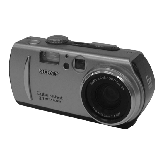
DIGITAL STILL CAMERA
US Model
UK Model
E Model
DSC-P30/P50
DSC-P50
Advertisement
Table of Contents

Related Manuals for Sony DSC-P30


Summary of Contents for Sony DSC-P30
- Page 1 DSC-P30/P50 SERVICE MANUAL US Model Canadian Model AEP Model Level 2 UK Model E Model Hong Kong Model Australian Model Ver 1.1 2001. 05 Chinese Model Korea Model Tourist Model Japanese Model DSC-P30/P50 Argentina Model Photo: DSC-P50 Brazilian Model DSC-P50 This service manual contains information for Japanese model as well.
- Page 2 SONY PARTS WHOSE PART NUMBERS APPEAR AS DE FONCTIONNEMENT. NE REMPLACER CES COM- SHOWN IN THIS MANUAL OR IN SUPPLEMENTS PUB- POSANTS QUE PAR DES PIÈCES SONY DONT LES LISHED BY SONY. NUMÉROS SONT DONNÉS DANS CE MANUEL OU DANS LES SUPPLÉMENTS PUBLIÉS PAR SONY.
-
Page 3: Table Of Contents
TABLE OF CONTENTS Section Title Page Section Title Page SERVICE NOTE ADJUSTMENTS ..............5 Self-diagnosis Display ............6 Before Starting Adjustment ............. 5-1 1-1. Adjusting Items when Replacing Main Parts and Boards ..........5-2 5-1. Camera Section Adjustment ......... 5-3 GENERAL 1-1. - Page 4 Section Title Page LED Check ..............5-41 Self Diagnosis Code ............5-41 REPAIR PARTS LIST 6-1. Exploded Views ............. 6-1 6-1-1. Cabinet (Front) Block Assembly ......6-1 6-1-2. Main Chassis Assembly ........... 6-2 6-1-3. Lens Block Assembly ..........6-3 6-1-4. Cabinet (Rear) Block Assembly ....... 6-4 6-2.
-
Page 5: Service Note
SERVICE NOTE • NOTE FOR REPAIR Make sure that the flat cable and flexible board are not cracked of When remove a connector, don’t pull at wire of connector. bent at the terminal. It is possible that a wire is snapped. Do not insert the cable insufficiently nor crookedly. -
Page 6: Self-Diagnosis Display
[Description on Self-diagnosis Display] Self-diagnosis display • C: ss: ss You can reverse the camera mal- function yourself. (However, con- tact your Sony dealer or local authorized Sony service facility when you cannot recover from the camera malfunction.) • E: ss: ss... -
Page 7: General
Note: In some areas the disposal of lithium ion batteries in household or business trash may be prohibited. For the Sony Service Center nearest you call 1-800-222-SONY (United States only) For the Customers in the Precaution on copyright When the camera is used for long U.S.A. -
Page 8: Introduction
Getting started Introduction Identifying the parts Checks the image after recording images See the pages in parentheses for details of operation. Recording still images: page 19 Playing back still images: page 28 Deleting images (DELETE): page 62 Captures images with your computer You can copy images onto your computer and view and modify images or attach images to e-mail on your computer using the supplied USB cable and application software. - Page 9 “InfoLITHIUM” battery pack (S series). “InfoLITHIUM” S series battery packs have the After charging the battery pack mark. “InfoLITHIUM” is a trademark of Sony Corporation. Disconnect the AC power adaptor from the DC IN jack on your camera. NP-FS11 battery pack (not supplied)
-
Page 10: Setting The Date And Time
Setting the date and time Set the numeric value with v/V on the control button, then press the center z to enter it. When you first use your camera, set the date and time. If these are not set, the Y / M / D CLOCK SET M / D / Y... -
Page 11: Recording Still Images
Recording still images Press the shutter button fully down. The shutter sounds. Still images are recorded in JPEG format. “RECORDING” appears on the LCD screen, and the image will be recorded on Before recording still images, press the POWER button to turn on the power and the “Memory Stick.”... -
Page 12: Recording Moving Images
Digital zoom function Recording images with the flash This camera has a digital zoom function. The factory setting is auto (no indicator). In this mode, the flash automatically Digital zoom enlarges the image by digital processing and it starts to function when strobes when the surroundings is dark. -
Page 13: Playing Back Still Images
B Playback Playing back still images Press the shutter button fully down. “REC” appears on the LCD screen, and the image is recorded on the “Memory Stick.” POWER Sound cannot be recorded with moving images. Press the shutter button fully down again to stop recording. The recording stops. - Page 14 The folders inside the “Memory Stick” are displayed. and drop). If the drive is not recognized, see “Troubleshooting” on page 75. • Sony USB Driver • Sony USB Shim When “Put these items into the Extensions folder?” appears, click “OK.”...
-
Page 15: Image File Storage Destinations And Image Files
For Windows Me and Windows 2000 users Select and double-click the desired image file from the folder. The following procedures are recommended when disconnecting the USB cable from For the detailed folder and file name, see “Image file storage destinations and your personal computer or ejecting the “Memory Stick”... -
Page 16: Before Performing Advanced Operations
Selects the image size when recording still ∞ (infinite) (IMAGE (DSC-P50) images (page 45). Sets the distance to the subject (page 52). SIZE) x 1280×960 (FOCUS) 7.0 m (DSC-P30) 3.0 m 1600 (3:2) 1.0 m (DSC-P50) 0.5 m 1280(3:2) x AUTO (DSC-P30) HOLD Sets the white balance (page 54). - Page 17 Approx. 7 Approx. 3 – 1600 (3:2) (DSC-P50) Approx. 7 Approx. 3 – 1280×960 (DSC-P30) Approx. 11 Approx. 6 – 1280 (3:2) (DSC-P30) Approx. 11 Approx. 6 – 1024×768 Approx. 16 Approx. 10 – 640×480 Approx. 57 Approx. 23 –...
-
Page 18: Various Recording
(page 45). TIFF images are recorded files (TIFF) in [1600×1200] (DSC-P50) or [1280×960] Mode dial: Notes (DSC-P30) size other than when [1600 • If the subject is not evenly illuminated, you Mode dial: (3:2)] (DSC-P50) or [1280 (3:2)] The TEXT mode is suitable for may be unable to record a clear image. - Page 19 Record the image for the first The number of Clip Motion frames Creating Clip Motion Setting the distance that you can record on a “Memory frame. Stick” (4 MB) Files to the subject Number of Mode dial: Image size Mode dial: images MAKING "CLIP MOTION"...
-
Page 20: Various Playback
To reactivate auto adjustment Record the image. Enjoying picture Recording the date The date and time do not appear on Select [AUTO] with v/V in step 3. effects (P. EFFECT) and time on the still the LCD screen during shooting. Tips These appear during playback image (DATE/TIME) -
Page 21: Editing
Notes To stop the SLIDE SHOW Enlarging a part of Playing back the still • You cannot zoom moving images. playback • You can zoom images recorded in TEXT the still image (Zoom images in order Press z, select [EXIT] with B, then mode, but cannot trim them. - Page 22 DSC-P50: In triple-image mode 1600×1200, 1024×768, 640×480 Select the images to be Press the zoom W button twice to DSC-P30: marked with the control turn to the triple-image mode. 1280×960, 1024×768, 640×480 button, then press z. Display the image you want to The resized image is recorded.
- Page 23 To unmark selected print You cannot divide the Step 1: Divide the unwanted scene A. Dividing a moving marks following types of files: image file (DIVIDE) • Clip Motion files Select the images to be unmarked in MOV0002.mpg step 5 with the control button, then •...
-
Page 24: Additional Information
∗ MagicGate is copyright protection power cord (mains lead) itself. dust may enter the inside of your camera, and contact your nearest Sony dealer. • Do not operate the unit with a damaged technology that uses encryption causing a malfunction. -
Page 25: Troubleshooting
(If you press the reset button, the date and time setting is cleared.) Should your camera still not operate properly, consult your Sony t Press the zoom button to set to the W side. -
Page 26: Warning And Notice Messages
Install the USB driver (page 32). the top. • [USB CONNECT] is set to [PTP] in the setup Click [ Sony DSC] in [ Other devices], then click the [Delete (E)] settings. button located at the lower-right corner. t Set it to [NORMAL] (page 70). -
Page 27: Self-Diagnosis Display
If you are unable to solve the problem even after trying the corrective actions a few times and when the camera is not reset even if you press the reset button located on the bottom, contact your Sony dealer or local authorized Sony service facility. - Page 28 • The focus is only aligned when the • When using size AA alkaline batteries, we shutter button is depressed halfway, recommend Sony Stamina alkaline even when auto focusing is activated. batteries. Other batteries may not bring out the full performance of the camera.
-
Page 29: Disassembly
DSC-P30/P50 SECTION 2 DISASSEMBLY • This set can be disassembled in the order shown below. DSC-P30/P50 2-1. CABINET (R) ASSEMBLY (Page 2-1) 2-2. CABINET (FRONT) BLOCK ASSEMBLY (Page 2-1) 2-3. DD-158 BOARD 2-4. CHASSIS (MAIN) 2-8. JK-206 BOARD (Page 2-2) -
Page 30: Board
2-3. DD-158 BOARD 1 Two flexible boards (CN003, 004) 3 Screw (DIA. 1.7 × 4) 2 Two connectors (CN001, 002) 5 DD-158 board 4 Screw (DIA. 1.7 × 4) [SERVICE POSITION (DD-158 BOARD)] Note 1: Don’t use the 12 pin flexible board of CPC-9 jig. It causes damage to the unit. -
Page 31: Chassis (Main) Assembly
2-4. CHASSIS (MAIN) ASSEMBLY 2-6. OPTICAL FINDER 1 Two screws 1 Two screws (DIA. 1.7 × 4) (DIA. 1.7 × 4) 2 Optical finder 2 Chassis (main) assembly 2-5. LENS BLOCK ASSEMBLY 2-7. ZOOM LENS 4 Screw 1 Screw (DIA. 1.7 × 4) (DIA. -
Page 32: Board
2-8. JK-206 BOARD 2-10. SY-66 BOARD 2 SY-66 board 3 Two flexible board (CN805, 806) 2 Flexible board (CN201) 1 JK-206 board 1 Four screws (M1.7 × 5) 2-9. DC JACK 2-11. LCD MODULE 6 LCD module 5 Two claws 4 Two claws 3 Light guide plate (1.5) block 1 Claw... - Page 33 [SERVICE POSITION (SY-66 BOARD)] • SIDE A Adjusting remote Zoom lens commander CPC-9 jig (J-6082-393-C) Regulated power supply Optical finder (6.0 to 7.2 Vdc) DC jack SY-66 board AC power AC IN adaptor Color monitor JK-206 board Note 1: Don’t use the 12 pin flexible board of CPC-9 jig. It causes damage to the unit.
-
Page 34: Circuit Boards Location
2-12. CIRCUIT BOARDS LOCATION SY-66 CAMERA PROCESS, LENS DRIVE, CAMERA DSP, VIDEO, MEMORY, SH DSP, CLOCK GENERATOR, USB I/F, DD-158 FRONT CONTROL, LCD DRIVE, DC IN, DC/DC CONVERTER, TIMING GENERATOR FLASH CHARGE CD-319 (CCD IMAGER) JK-206 (JACK) 2-13. FLEXIBLE BOARDS LOCATION Strobo flexible block assembly Optical finder FP-054... -
Page 35: Block Diagrams
DSC-P30/P50 SECTION 3 BLOCK DIAGRAMS 3-1. OVERALL BLOCK DIAGRAM JK-206 BOARD (2/3) CD-319 BOARD SY-66 BOARD CAM SI, CAM SO, XCAM SCK (SEE PAGE 4-29) LENS IRIS J201 METER Y OUT IC102 Y OUT IC401 VIDEO OUT IC651 C OUT... -
Page 36: Power Block Diagram 1
DSC-P30/P50 3-8. POWER BLOCK DIAGRAM 1 FLASH UNIT DD-158 BOARD T501 CN501 Q019 Q501, 502 L004 F001 XE-A ST 5V SWITCHING ı BATT /XEXT J001 Q106 CN001 DC IN F002, 005 AF LED 5V SENS-A ACV UNREG AF ILLUMINATOR Q007... -
Page 37: Power Block Diagram 2
DSC-P30/P50 3-9. POWER BLOCK DIAGRAM 2 JK-206 BOARD (1/2) CD-319 BOARD SY-66 BOARD (SEE PAGE 4-29) CN201 (1/2) CN703 (1/2) VL 3V BT201 LITHIUM BATTERY Q102 – 105 CN101 CN401 D101 FB113 CAM 15V CAM 15V CAM 15V BACKUP VCC... -
Page 38: Printed Wiring Boards And Schematic Diagrams
DSC-P30/P50 SECTION 4 PRINTED WIRING BOARDS AND SCHEMATIC DIAGRAMS THIS NOTE IS COMMON FOR WIRING BOARDS AND SCHEMATIC DIAGRAMS (In addition to this, the necessary note is printed in each block) (For printed wiring boards) (Measuring conditions voltage and waveform) •... -
Page 39: Frame Schematic Diagrams
DSC-P30/P50 4-1. FRAME SCHEMATIC DIAGRAMS FRAME SCHEMATIC DIAGRAM CONTROL SWITCH BLOCK S004 D001 S002 POWER MODE CPC(FOR CHECK) ON/OFF DIAL (POWER (GREEN)) BZ701 S003 BUZZER (SHUTTER) CD-319 BOARD CN101 CN401 CN805 CCD_TEMP CCD_TEMP TESTL CAM_-7.5V CAM_-7.5V VDDG VSSG LCD901 WIDE... -
Page 40: Printed Wiring Boards And Schematic Diagrams
DSC-P30/P50 4-2. PRINTED WIRING BOARDS AND SCHEMATIC DIAGRAMS CD-319 (CCD IMAGER) PRINTED WIRING BOARD AND SCHEMATIC DIAGRAM • See page 4-41 for waveforms. – Ref. No.: CD-319 board; 2,000 series – • For Printed Wiring Board. • :Uses unleaded solder. -
Page 41: Printed Wiring Board
DSC-P30/P50 JK-206 (JACK) PRINTED WIRING BOARD – Ref. No.: JK-206 board; 2,000 series – • For Printed Wiring Board. BT201 • :Uses unleaded solder. BATTERY, • There are a few cases that the part isn't mounted in this model is printed on this diagram. - Page 42 DSC-P30/P50 JK-206 (JACK) SCHEMATIC DIAGRAM • See page 4-27 printed wiring board. JK-206 BOARD JACK CN204 -REF.NO.:2,000 SERIES- (MS SOCKET) XX MARK:NO MOUNT D214 CL-270HR-C-TS (ACCESS LED(RED)) MS_BS MS_DIO R213 XMS_IN MS_SCLK SCLK BT201 MS_VCC R214 CN201 (LITHIUM BATTERY) C204 VL_3V 0.1u...
-
Page 43: Printed Wiring Board
DSC-P30/P50 DD-158 (DC IN, DC/DC CONVERTER, FLASH CHARGE) PRINTED WIRING BOARD • For Printed Wiring Board. – Ref. No.: DD-158 board; 2,000 series – • :Uses unleaded solder. • DD-158 board is four-layer print board. However, the patterns of layers 2 to 3 have not been included in the diagram. - Page 44 DSC-P30/P50 4-34 DC IN, DC/DC CONVERTER, FLASH CHARGE 4-33 DD-158...
-
Page 45: Dc In) Schematic Diagram
DSC-P30/P50 DD-158 (DC IN) SCHEMATIC DIAGRAM • See page 4-31 for DD-158 printed wiring board. DD-158 BOARD (1/3) DC IN(DD BLOCK 1/2) -REF.NO.:2,000 SERIES- Note:Resistors are mounted to the location XX MARK:NO MOUNT where F001-F006 are printed. NO MARK:REC/PB MODE... -
Page 46: Dd-158 (Dc/Dc Converter) Schematic Diagram
DSC-P30/P50 DD-158 (DC/DC CONVERTER) SCHEMATIC DIAGRAM • See page 4-31 for DD-158 printed wiring board. DD-158 BOARD (2/3) DC/DC CONVERTER(DD BLOCK 2/2) -REF.NO.:2,000 SERIES- XX MARK:NO MOUNT NO MARK:REC/PB MODE L020 Q011 D011 4.7uH 1SS357-TPH3 MCH3306-TL Q011,014 SWITCHING L006 22uH... -
Page 47: Flash Charge) Schematic Diagram
DSC-P30/P50 DD-158 (FLASH CHARGE) SCHEMATIC DIAGRAM • See page 4-31 for DD-158 printed wiring board. DD-158 BOARD (3/3) NO MARK:DVD/CD PLAY R:REC MODE P:PB MODE FLASH CHARGE(STB CHARGE BLOCK) :IMPOSSIBLE TO MEASURE THE VOLTAGE AT THE MARKED POINTS. -REF.NO.:2,000 SERIES-... -
Page 48: Waveforms
4-3. WAVEFORMS CD-319 BOARD 8.0 Vp-p 100 µsec IC401 1, 2, 3 REC 8.0 Vp-p 100 µsec IC401 4, 5, 6 REC 650 mVp-p 100 µsec IC401 8 REC 3.0 Vp-p 18.4 MHz IC401 qf REC 4.5 Vp-p 17.1 MHz IC401 qg REC 4.2 Vp-p 17.1 MHz... -
Page 49: Parts Location
4-4. PARTS LOCATION no mark : SIDE A * mark : SIDE B CD-319 BOARD JK-206 BOARD DD-158 BOARD * C401 BT201 C002 * IC002 * R024 C402 C003 R025 * C403 C204 C004 L001 R027 * C404 C005 L002 R029 * C405 CN201... -
Page 50: Adjustments
DSC-P30/P50 SECTION 5 ADJUSTMENTS Before starting adjustment EVR Data Re-writing Procedure When Replacing Board The data that is stored in the repair board, is not necessarily correct. Perform either procedure 1 or procedure 2 or procedure 3 when replacing board. -
Page 51: Adjusting Items When Replacing Main Parts And Boards
1-1. Adjusting items when replacing main parts and boards When replacing main parts and boards, adjust the items indicated by z in the following table. Replaced parts Block Mounted parts replacement replacement Adjustment section Adjustment Initialization of D page data Initialization of 7, 9, B, D, E, F, page data Initialization of 7, 9, B, E, F page data... -
Page 52: Camera Section Adjustment
5-1. CAMERA SECTION ADJUSTMENT 1-1. PREPARATIONS BEFORE ADJUSTMENT 1-1-1. List of Service Tools • Oscilloscope • Color monitor • Vectorscope • Regulated power supply • Digital voltmeter Ref. No. Name Parts Code Usage Auto white balance adjustment/check Filter for color temperature correction (C14) J-6080-058-A White balance adjustment/check Pattern box PTB-450... -
Page 53: Preparations
1-1-2. Preparations Note 1: For details of how remove the cabinet and boards, refer to “2. DISASSEMBLY”. Pattern box Note 2: When performing only the adjustments, the lens block and boards need not be disassemble. 1) Connect the equipment for adjustments according to Fig. 5-1- 2) Connect the Adjusting remote commander to SY-66 board CN706 via CPC-9 jig (J-6082-393-C). - Page 54 Note 1: Don’t use the 12 pin flexible board of CPC-9 jig. It causes damage to the unit. Note 2: The old CPC-9 jig (Parts code: J-6082-393-B) cannot be used, because it cannot operate the adjusting remote commander. Regulated power supply Color monitor Vectorscope (6.0 to 7.2 Vdc)
-
Page 55: Precautions
1-1-4. Precautions 1. Setting the Switch Unless otherwise specified, set the switches as follows and per- form adjustments. 1. PLAY/CAMERA/MOVIE switch (Mode Dial) ..CAMERA 2. FOCUS (Menu display) ......... AUTO 3. EV (Menu display) ..........0EV 4. DISPLAY/LCD ON/OFF button (SY-66 board S253) .......... -
Page 56: Preparing The Flash Adjustment Box
4. Preparing the Flash Adjustment Box A dark room is required to provide an accurate flash adjustment. If it is not available, prepare the flash adjustment box as given below; 1) Provide woody board A, B and C of 15 mm thickness. woody board A (2) woody board B (2) woody board C (1) -
Page 57: Initialization Of B, D, E, F
1-2. INITIALIZATION OF B, D, E, F, 7, 9 PAGE DATA 3. D Page Table Note 1: Fixed data-1: Initialized data. 1-2-1. Initialization of D Page Data (Refer to “1. Initializing of D Page Data”) 1. Initializing D Page Data Note 2: Fixed data-2: Modified data. -
Page 58: Initialization Of B, E, F, 7, 9 Page Data
1-2-2. Initialization of B, E, F, 7, 9 Page Data 3. B Page Table 1. Initializing B, E, F, 7, 9 Page Data Note 1: Fixed data-1: Initialized data. Note: If the B, E, F, 7, 9 Page data has been initialized, (Refer to “1. -
Page 59: F Page Table
5. F Page Table Note 1: Fixed data-1: Initialized data. (Refer to “1. Initializing of B, E, F, 7, 9 Page Data”) Note 2: Fixed data-2: Modified data. (Refer to “2. Modification of B, E, F, 7, 9 Page Data”) Initial value Initial value Address... - Page 60 Initial value Address Remark A4 to A8 Fixed data-1 (Initialized data) Auto white balance adj. AB to D3 Fixed data-1 (Initialized data) Mechanical shutter adj. D9 to FF Fixed data-1 (Initialized data) 5-11...
-
Page 61: Page Table
6. 7 Page Table Note 1: Fixed data-1: Initialized data. (Refer to “1. Initializing B, E, F, 7, 9 Page Data”) Note 2: Fixed data-2: Modified data. (Refer to “2. Modification of B, E, F, 7, 9 Page Data”) Address Initial value Remark Address... -
Page 62: Video System Adjustments
1-3. VIDEO SYSTEM ADJUSTMENTS 2. Video Burst Level Adjustment Adjust the burst level of the composite video signal output. 1. Video Sync Level Adjustment Adjust the sync level of the composite video signal output. Mode PLAY Mode PLAY Signal Arbitrary Signal Arbitrary Measurement Point... -
Page 63: Camera System Adjustment
1-4. CAMERA SYSTEM ADJUSTMENTS Before perform the camera system adjustments, check that the specified values of “VIDEO SYSTEM ADJUSTMENTS” are sat- isfied. Note: For “CAMERA SYSTEM ADJUSTMENTS”, perform in order of item numbers. Data setting during camera system adjustments Perform the following data setting before the camera system ad- justments. -
Page 64: Hall Adjustment
1. HALL Adjustment Processing after Completing Adjustment: For detecting the position of lens iris, adjust the HALL AMP gain Order Page Address Data Procedure and offset. Mode CAMERA Press PAUSE button. Subject Not required Measurement Point Displayed data of page: 1 (Note 2) Measuring Instrument Adjusting remote commander Release the data setting... -
Page 65: Flange Back Adjustment
2. Flange Back Adjustment (Using the minipattern box) Specified voltage: The specified voltage varies according to the The flange back of inner focus lens is adjusted automatically. If minipattern box, so adjustment the power sup- shifted, the auto focus is disordered. ply output voltage to the specified voltage writ- ten on the sheet which is supplied with the mini- Mode... - Page 66 3. Flange Back Adjustment Adjusting method: (Using the flange back adjustment chart and 9 Order Page Address Data Procedure subject more than 500 m away) The flange back of inner focus lens is adjusted automatically. If shifted, the auto focus is disordered. Perform “Data setting during camera system adjustments”.
-
Page 67: Flange Back Check
4. Flange Back Check 3-2. Flange Back Adjustment (2) Perform this adjustment after performing “Flange Back Adjust- Mode CAMERA ment (1)”. Subject Siemens star chart Mode CAMERA (1.0 m from the front of the lens) Subject Subject more than 500 m away (Luminance: 200 to 400 lux) (Subjects with clear contrast such Measurement Point... -
Page 68: Picture Frame Setting
5. Picture Frame Setting How to reset the zoom and focus when they deviated: Order Page Address Data Procedure Mode CAMERA Subject Color bar chart (Color reproduction adjustment frame with the zoom lens at WIDE end) (Note 2) Measurement Point Video terminal of A/V OUT jack (Note 2) (75 Ω... -
Page 69: F No. Standard Data Input
6. F No. Standard Data Input 7. Mechanical Shutter Adjustment Compensate the unevenness of the iris meter sensitivity. Adjust the period which the mechanical shutter is closed, and com- pensate the exposure. Mode CAMERA Mode CAMERA Subject Clear chart (Color reproduction adjustment Subject Clear chart frame with the zoom lens at WIDE... -
Page 70: Light Level Adjustment
8. Light Level Adjustment 9. Mixed Color Cancel Adjustment Adjust the standard LV value. To perform mixed color cancel adjustment based on data of each color in color bar. Mode CAMERA Mode CAMERA Subject Clear chart (Color reproduction adjustment Subject Color bar chart frame with the zoom lens at (Color reproduction adjustment... -
Page 71: Auto White Balance Standard Data Input
10. Auto White Balance Standard Data Input Adjust the white balance standard data at 3200K. Mode CAMERA Subject Clear chart (Color reproduction adjustment frame with the zoom lens at WIDE end) Adjustment Page Adjustment Address 3A to 3D, 59 Note 1: Check that the data of page: 6, address: 02 is “00”. If not, turn the power of unit OFF/ON. -
Page 72: Auto White Balance Adjustment
11. Auto White Balance Adjustment Order Page Address Data Procedure Adjust to the proper auto white balance output data. Press PAUSE button. (Note 6) If it is not correct, auto white balance and color reproducibility Check the data changes to “01”. will be poor. -
Page 73: Color Reproduction Adjustment
12. Color Reproduction Adjustment Processing after Completing Adjustment: Adjust the color separation matrix coefficient so that proper color Order Page Address Data Procedure reproduction is produced. Press PAUSE button. Mode CAMERA Subject Color bar chart (Color reproduction adjustment frame with the zoom lens at Release the data setting WIDE end) performed at step 2 . -
Page 74: Color Reproduction Check
13. Color Reproduction Check Processing after Completing Adjustment: Order Page Address Data Procedure Mode CAMERA Press PAUSE button. Subject Color bar chart (Color reproduction adjustment frame with the zoom lens at WIDE end) Measurement Point Video terminal of A/V OUT jack (75 Ω... -
Page 75: Auto White Balance Check
Ver 1.1 2001. 05 14. Auto White Balance Check OUTDOOR luminance check Place the C14 filter on the lens. Mode CAMERA Note down the data. Subject Clear chart (Color reproduction adjustment Press PAUSE button. frame with the zoom lens at Press PAUSE button. -
Page 76: Ccd White Defect Compensation
15. CCD White Defect Compensation Mode CAMERA Subject Not required Measurement Point Displayed data of page: 6, address: 55 Measuring Instrument Adjusting remote commander Adjustment Page Adjustment Address 88 to A3 Note 1: Check that the data of page: 6, address: 02 is “00”. If not, turn the power of unit OFF/ON. -
Page 77: Ccd Black Defect Compensation
16. CCD Black Defect Compensation Processing after Completing Adjustment: Order Page Address Data Procedure Mode CAMERA Press PAUSE button. Subject Clear chart (Color reproduction adjustment frame) Measurement Point Displayed data of page: 6, address: 55 Set the data noted down at step Measuring Instrument Adjusting remote commander 3, and press PAUSE button. -
Page 78: Strobe White Balance Adjustment
17. Strobe White Balance Adjustment Adjusting method: Adjust the white balance when the strobe light flashed. Order Page Address Data Procedure Mode CAMERA Perform “Data setting during Subject Flash adjustment box (Note 3) camera system adjustments”. (1.0 m from the front of the lens) (Refer to page 5-14) Adjustment Page Adjustment Address... -
Page 79: Lcd System Adjustments
1-5. LCD SYSTEM ADJUSTMENTS [Adjusting connector] Most of the measuring points for adjusting the LCD system are Before perform the LCD system adjustments, check that the concentrated in CN706 of the SY-66 board. specified values of “VIDEO SYSTEM ADJUSTMENTS” are sat- Connect the Measuring Instruments via the CPC-9 jig (J-6082- isfied. -
Page 80: Lcd Initial Data Input (1)
1. LCD Initial Data Input (1) 2. LCD Initial Data Input (2) Mode PLAY Mode PLAY Signal Arbitrary Signal Arbitrary Adjustment Page Adjustment Page Adjustment Address 3A to 3F Adjustment Address CE to DA, DC to DF Adjusting method: Adjusting method: 1) Select page: 0, address: 01, and set data: 01. -
Page 81: Vco Adjustment (Sy-66 Board)
3. VCO Adjustment (SY-66 Board) Set the VCO free-run frequency. If deviated, the LCD screen will be blurred. Mode PLAY Signal Arbitrary Measurement Point CH1: Pin 7 of CN706 (HSY) CH2: Video terminal of A/V OUTjack (75 Ω terminated) Measuring Instrument Oscilloscope Adjustment Page magnified... -
Page 82: Black Limit Adjustment (Sy-66 Board)
4. Black Limit Adjustment (SY-66 Board) Set the maximum amplitude of the RGB decoder for driving the LCD to the specified value. If deviated, the LCD screen image will be blackish or saturated (whitish). Mode PLAY Signal Arbitrary Measurement Point Pin 9 of CN706 (VG) External trigger: Pin 8 of CN706 (PEARL COM) -
Page 83: Bright Adjustment (Sy-66 Board)
5. Bright Adjustment (SY-66 Board) Pedestal Set the amplitude of the RGB decoder for driving the LCD to the specified value. If deviated, the LCD screen image will be blackish or saturated (whitish). Mode PLAY Signal Arbitrary Measurement Point Pin 9 of CN706 (VG) External trigger: Pin 8 of CN706 (PEARL COM) Measuring Instrument... -
Page 84: Contrast Adjustment (Sy-66 Board)
6. Contrast Adjustment (SY-66 Board) 7. Color Adjustment (SY-66 Board) Set the level of the VIDEO signal for driving the LCD to the Set the color saturation to the standard value. specified value. If, deviated, the color will be dark or light. If deviated, the LCD screen image will be blackish or saturated (whitish). -
Page 85: Vg Center Adjustment (Sy-66 Board)
8. VG Center Adjustment (SY-66 Board) 9. V-COM Adjustment (SY-66 Board) Set the center of VG signal for driving the LCD to the specified Set the DC bias of the common electrode drive signal of LCD to value. the specified value. If deviated, the LCD display will be move, producing flicker and Mode PLAY... -
Page 86: White Balance Adjustment (Sy-66 Board)
10. White Balance Adjustment (SY-66 Board) Correct the white balance. If deviated, the LCD screen color cannot be reproduced. Mode PLAY Signal Arbitrary Measurement Point Check on the LCD screen Measuring Instrument Adjustment Page Adjustment Address D2, D3 Specified Value LCD screen must not be colored Note 1: Check the white balance only when replacing the fol- lowing parts. -
Page 87: Service Mode
5-2. SERVICE MODE • Changing the address The address increases when the FF (M) button is pressed, 2-1. ADJUSTING REMOTE COMMANDER and decreases when the REW (M) button is pressed. There The adjusting remote commander is used for changing the calcu- are altogether 256 addresses, from 00 to FF. -
Page 88: Data Process
2-2. DATA PROCESS The calculation of the adjusting remote commander display data (hexadecimal notation) are required for obtaining the adjustment data of some adjustment items. In this case, after converting the hexadecimal notation to decimal notation, calculate and convert the result to hexadecimal notation, and use it as the adjustment data. -
Page 89: Service Mode
3. Mode Dial Check (1) 2-3. SERVICE MODE 1. Setting the Test Mode Page 2 Address 94 Page D Address 10 Data Function Data Function 00 to 14 MOVIE Normal 15 to 3D TWILIGHT Forced CAMERA mode power ON 3E to 67 CAMERA Forced PLAY mode power ON Using method:... -
Page 90: Switch Check (2)
6. Switch Check (2) Page 2 Addresses 90, 91, 93 Using method: 1) Select page: 2, addresses: 90, 91 and 93. 2) By discriminating the dispaly data, the pressed key can be discriminated. Data Address 00 to 0C 0D to 27 28 to 49 4A to 76 77 to AA... -
Page 91: Repair Parts List
DSC-P30/P50 SECTION 6 Ver 1.1 2001. 05 REPAIR PARTS LIST 6-1. EXPLODED VIEWS The components identified by mark 0 or dotted line with mark 0 are NOTE: critical for safety. • -XX and -X mean standardized parts, so they may •... -
Page 92: Main Chassis Assembly
Ver 1.1 2001. 05 6-1-2. MAIN CHASSIS ASSEMBLY supplied supplied Lens block assembly (See page 6-3.) supplied supplied supplied supplied supplied supplied supplied BT901 not supplied not supplied Cabinet (rear) block assembly (See page 6-4.) : BT201 (BATTERY, LITHIUM SECONDARY) Board on the mount position. -
Page 93: Lens Block Assembly
6-1-3. LENS BLOCK ASSEMBLY not supplied not supplied BZ701 IC401 (Note) (Note ) Be sure to read “Precuations for Replacement of CCD Imager” on page 4-6 when changing the CCD imager. Ref. No. Part No. Description Remark Ref. No. Part No. Description Remark 1-758-620-11 LENS, ZOOM (DE01) -
Page 94: Cabinet (Rear) Block Assembly
Ver 1.1 2001. 05 6-1-4. CABINET (REAR) BLOCK ASSEMBLY not supplied supplied LCD901 D901 J001 not supplied The components identified by Les composants identifiés par une mark 0 or dotted line with marque 0 sont critiques pour la mark 0 are critical for safety. sécurité. -
Page 95: Electrical Parts List
CD-319 6-2. ELECTRICAL PARTS LIST NOTE: The components identified by • Due to standardization, replacements in the • Items marked “*” are not stocked since they mark 0 or dotted line with mark parts list may be different from the parts speci- are seldom required for routine service. - Page 96 DD-158 Ref. No. Part No. Description Remark Ref. No. Part No. Description Remark A-7074-846-A DD-158 BOARD, COMPLETE C103 1-162-969-11 CERAMIC CHIP 0.0068uF 10% C104 1-104-851-11 TANTAL. CHIP 10uF *********************** (Ref.No.: 2,000 Series) C105 1-113-682-11 TANTAL. CHIP 33uF < CAPACITOR > C107 1-125-777-11 CERAMIC CHIP 0.1uF...
- Page 97 DD-158 Ref. No. Part No. Description Remark Ref. No. Part No. Description Remark < COIL > Q031 8-729-037-61 TRANSISTOR UN9113J- (K8).SO Q032 8-729-053-52 TRANSISTOR N1C01FE-Y/GR (TPLR3) L001 1-416-669-11 INDUCTOR 22uH Q033 8-729-037-74 TRANSISTOR UN9213J- (K8).SO L002 1-424-846-11 INDUCTOR L003 1-416-669-11 INDUCTOR 22uH Q034 8-729-053-54 TRANSISTOR...
- Page 98 Ver 1.1 2001. 05 DD-158 JK-206 Ref. No. Part No. Description Remark Ref. No. Part No. Description Remark R055 1-218-985-11 RES-CHIP 470K 1/16W R056 1-218-985-11 RES-CHIP 470K 1/16W < CONNECTOR > R063 1-218-977-11 RES-CHIP 100K 1/16W R064 1-218-976-11 RES-CHIP 1/16W CN201 1-794-321-21 CONNECTOR, FFC (ZIF) 18P CN202...
- Page 99 Ver 1.1 2001. 05 Ref. No. Part No. Description Remark Ref. No. Part No. Description Remark ACCESSORIES ************ 1-757-293-11 CORD, CONNECTION (USB 5P) 1-783-738-31 CORD, CONNECTION (AV CONNECTING) (EXCEPT J) 1-792-955-11 CORD, CONNECTION (VIDEO CONNECTING)(J) 3-065-665-01 MANUAL, INSTRUCTION (for SAFETY) (JAPANESE) (J) 3-066-676-01 SPVD-004 (P) (CD-ROM) (US, CND, J) 3-066-677-01 SPVD-004 (I) (CD-ROM) (EXCEPT US, CND, J)
- Page 100 FOR CAMERA COLOR REPRODUCTION ADJUSTMENT Take a copy of CAMERA COLOR For NTSC mode REPRODUCTION FRAME with a clear sheet for use. DSC-P30/P50 – 117 –...
- Page 101 DSC-P30/P50 2001E0500-1 Sony EMCS Co. Kohda TEC 9-929-893-32 © 2001. 5 – 118 – Published by PV Customer Center...
-
Page 102: Revision History
Reverse 992989332.pdf Revision History S.M. Rev. Ver. Date History Contents issued 2001.04 Official Release — — S.M. correction:Page 5-26, Page 6-1, 2001.05 Correction Page 6-2, Page 6-4, Page 6-8, Page 6-15...