Table of Contents
Advertisement
Advertisement
Table of Contents

Related Manuals for MSI MS-7082


Summary of Contents for MSI MS-7082
- Page 1 661FM3 Series MS-7082 (v1.X) Micro ATX Mainboard G52-M7082X3...
-
Page 2: Fcc-B Radio Frequency Interference Statement
Notice 2 Shielded interface cables and A.C. power cord, if any, must be used in order to comply with the emission limits. VOIR LA NOTICE D’INSTALLATION AVANT DE RACCORDER AU RESEAU. Micro-Star International MS-7082... -
Page 3: Copyright Notice
Copyright Notice The material in this document is the intellectual property of MICRO-STAR INTERNATIONAL. We take every care in the preparation of this document, but no guarantee is given as to the correctness of its contents. Our products are under continual improvement and we reserve the right to make changes without notice. -
Page 4: Safety Instructions
Safety Instructions Always read the safety instructions carefully. Keep this User’s Manual for future reference. Keep this equipment away from humidity. Lay this equipment on a reliable flat surface before setting it up. The openings on the enclosure are for air convection hence protects the equipment from overheating. -
Page 5: Table Of Contents
CONTENTS FCC-B Radio Frequency Interference Statement ........... ii Copyright Notice ..................iii Revision History ................... iii Safety Instructions ..................iv Chapter 1. Getting Started ................ 1-1 Mainboard Specifications ..............1-2 Mainboard Layout ................1-4 Chapter 2. Hardware Setup ............... 2-1 Quick Components Guide .............. - Page 6 Fan Power Connectors: CPUFAN2 & POWFAN1& CHSFAN1 ... 2-16 Hard Disk Connectors: IDE1 & IDE2 ........... 2-17 Serial ATA HDD Connectors: SATA1 & SATA2 ......2-18 IEEE 1394 Connector: J1394_1 (Optional) ........2-19 Serial Port Connector: JCOM1 ............. 2-19 Front Panel Connectors: JFP1 ............. 2-20 Aux Line-In Connector: AUX_IN1 ..........
-
Page 7: Chapter 1. Getting Started
Hardware Setup Chapter 1. Getting Started Getting Started Thank you for purchasing 661FM3 Series (MS-7082 v1.X) Micro ATX ® mainboard. The 661FM3 Series (MS-7082 v1.X) is based on SiS ® 661FX / 648FX & SiS 964 / 964L chipsets for optimal system efficiency. -
Page 8: Mainboard Specifications
Pentium 4 / Celeron-D in the 775-land package Supports 533MHz, 800MHz FSB Supports 2004 Performance FMB CPU VR Design Supports 3/4 pin CPU Fan Pin-Header with Fan Speed Control (For the latest information about CPU, please visit http://www.msi.com.tw/program/ products/mainboard/mbd/pro_mbd_cpu_support.php ) Chipset ®... -
Page 9: Hardware Setup
Hardware Setup Audio High Definition link controller integrated in 964/964L 6 channels (HDA) audio codec - Meet PC2001 audio performance requirement - Can support SPDIF Out via bracket only On-Board LAN (Optional) RealtekR 8100C / 8110S (optional) - Integrated Fast Ethernet MAC and PHY in one chip. - Supports 10Mb/s, 100Mb/s and 1000Mb/s (1000Mb/s for 8110S only). -
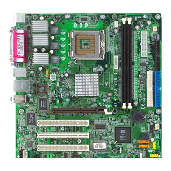
Page 10: Mainboard Layout
Lin e-In Lin e-Out Winb ond AGP Slot W83687T HF BATT RTL8100C/ PCI 1 8110S JFP1 PCI 2 964/964L JUSB2 Codec SATA2 PCI 3 SATA1 VT6307 AUX_IN1 JMR1 J1394_1(Optional) JWOL JCOM1 JAUD1 JSP1 JBAT1 JUSB1 MS-7082 v1.X Micro ATX Mainboard... -
Page 11: Chapter 2. Hardware Setup
Hardware Setup Chapter 2. Hardware Setup Hardware Setup This chapter tells you how to install the CPU, memory modules, and expansion cards, as well as how to setup the jumpers on the mainboard. It also provides the instructions on connecting the peripheral devices, such as the mouse, keyboard, etc. -
Page 12: Quick Components Guide
MS-7082 Micro ATX Mainboard Quick Components Guide CPUFAN2, p.2-16 JPW2000, p.2-9 CPU, p.2-3 DDR DIMMs, p.2-7 CONN1, p.2-9 PWRFAN1, p.2-16 FDD1, p.2-16 Back Panel I/O, p.2-10 BIOS_WP1, p.2-24 IR1, p.2-23 IDE1, IDE2, p.2-17 CFSFAN1, p.2-16 JFP1, p.2-20 SATA1/2, p.2-18 PCI Slots, p.2-25 JUSB2, p.2-22... -
Page 13: Central Processing Unit: Cpu
If you do not have the CPU, contact your dealer to purchase and install them before turning on the computer. For the latest information about CPU, please visit http://www.msi.com.tw/pro- gram/products/mainboard/mbd/pro_mbd_cpu_support.php. MSI Reminds You... - Page 14 MS-7082 Micro ATX Mainboard CPU, Heatsink & Fan Installation When you are installing the CPU, make sure the CPU has a heat sink/ cooler fan attached on the top to prevent overheating. If you do not have the heat sink/cooler fan, contact your dealer to purchase and install them before turning on the computer.
- Page 15 Hardware Setup 5. Lift the load lever up and open the 6. After confirming the CPU direction load plate. for correction mating, put down the CPU in the socket housing frame. Be sure to grape on the edge of the substrate.
- Page 16 MS-7082 Micro ATX Mainboard 9. Engage the load while pressing 10. Align the holes on the mainboard down lightly onto the load plate, and with the heatsink first. Pull down then secure the lever with the hook the fan/heatsink until its four clips under retention tab.
-
Page 17: Memory
The mainboard provides two 184-pin unbuffered DDR266/DDR333/DDR400 DDR SDRAM, and supports the memory size up to 2GB without ECC. To operate properly, at least one DIMM module must be installed. (For the updated supporting memory modules, please visit http://www.msi.com.tw/ program/products/mainboard/mbd/pro_mbd_trp_list.php ) DDR DIMM Slots... -
Page 18: Ddr Module Combination
MS-7082 Micro ATX Mainboard DDR Module Combination Install at least one DIMM module on the slots. Memory modules can be installed on the slots in any order. You can install either single- or double-sided modules to meet your own needs. -
Page 19: Power Supply
PW_OK 5V_SB CONN1 ATX 12V Power Connector: JPW2000 This 12V power connector is used to provide power to the CPU. JPW1 Pin Definition SIGNAL JPW2000 MSI Reminds You... Power supply of 300-watt (and above) is highly recommended for system stability. -
Page 20: Back Panel
MS-7082 Micro ATX Mainboard Back Panel The back panel provides the following connectors: L-in L-out 1394 Parallel (Optional) Mouse (Optional) Keyboard COM Port VGA Port USB Port USB Port (for 661FX only) Mouse Connector The mainboard provides a standard PS/2 ®... -
Page 21: Keyboard Connector
Hardware Setup Keyboard Connector ® The mainboard provides a standard PS/2 keyboard mini DIN connector for attaching a ® ® PS/2 keyboard. You can plug a PS/2 keyboard directly into this connector. Pin Definition SIGNAL DESCRIPTION Keyboard DATA Keyboard DATA No connection Ground Keyboard Clock... -
Page 22: Serial Port Connector
MS-7082 Micro ATX Mainboard Serial Port Connector The mainboard offers one 9-pin male DIN connector. It is 16550A high speed communi- cation port that sends/receives/ 16 bytes FIFOs. You can attach a serial mouse or other serial device directly to it. -
Page 23: Rj-45 Lan Jack
Hardware Setup RJ-45 LAN Jack: 10/100 LAN (8100C) /Giga-bit LAN (8110S) (Optional) The mainboard provides one standard RJ-45 jack for connection to Local Area Network (LAN). Giga-bit LAN enables data to be transferred at 1000, 100 or 10Mbps. You can connect a network cable to either LAN jack. Activity Indicator Link Indicator RJ-45 LAN Jack... -
Page 24: Audio Port Connectors
MS-7082 Micro ATX Mainboard Audio Port Connectors Line Out is a connector for Speakers or Headphones. Line In is used for external CD player, Tape player, or other audio devices. Mic is a connector for microphones. Line In 1/8” Stereo Audio Connectors Line Out MSI Reminds You... -
Page 25: Parallel Port Connector: Lpt1
Hardware Setup Parallel Port Connector: LPT1 The mainboard provides a 25-pin female centronic connector as LPT. A parallel port is a standard printer port that supports Enhanced Parallel Port (EPP) and Extended Capa- bilities Parallel Port (ECP) mode. Pin Definition SIGNAL DESCRIPTION STROBE... -
Page 26: Connectors
MS-7082 Micro ATX Mainboard Connectors The mainboard provides connectors to connect to FDD, IDE HDD, case, LAN, USB Ports, IR module and CPU/System/Power Supply FAN. Floppy Disk Drive Connector: FDD1 The mainboard provides a standard floppy disk drive connector that supports 360K, 720K, 1.2M, 1.44M and 2.88M floppy disk types. -
Page 27: Hard Disk Connectors: Ide1 & Ide2
IDE2 (Secondary IDE Connector) IDE2 can also connect a Master and a Slave drive. MSI Reminds You... If you install two hard disks on cable, you must configure the second drive to Slave mode by setting its jumper. Refer to the hard disk documentation supplied by hard disk vendors for jumper setting instructions. -
Page 28: Serial Ata Hdd Connectors: Sata1 & Sata2
MS-7082 Micro ATX Mainboard Serial ATA HDD Connectors: SATA1 & SATA2 The mainboard provides dual high-speed Serial ATA interface ports. The ports support generation Serial ATA data rates of 150MB/s and are fully compliant with Serial ATA 1.0 specifications. Each Serial ATA connector can connect to 1 hard disk drive. -
Page 29: Ieee 1394 Connector: J1394_1 (Optional)
Hardware Setup IEEE 1394 Connector: J1394_1 (Optional) The mainboard provides one IEEE1394 pin header that allows you to connect IEEE 1394 ports via an external IEEE1394 bracket (optional). Pin Definition SIGNAL SIGNAL TPA+ TPA- Ground Ground TPB+ TPB- J1394_1 Cable power Cable power Key (no pin) Ground... -
Page 30: Front Panel Connectors: Jfp1
MS-7082 Micro ATX Mainboard Front Panel Connectors: JFP1 The mainboard provides one front panel connector JFP1 for electrical connection to the front panel switches and LEDs. It is compliant with Intel ® Front Panel I/O Connectivity Design Guide. JFP1 Pin Definition... -
Page 31: Cd-In Connector: Cd_In1
Left channel audio signal to front panel AUD_RET_L Left channel audio signal return from front panel MSI Reminds You... If you don’t want to connect to the front audio header, pins 5 & 6, 9 & 10 have to be jumpered in order to have signal output directed to the rear audio ports. -
Page 32: Front Usb Connectors: Jusb1 & Jusb2
MS-7082 Micro ATX Mainboard Front USB Connectors: JUSB1 & JUSB2 The mainboard provides two USB 2.0 pin headers JUSB1/JUSB2 that are compliant ® with Intel I/O Connectivity Design Guide. USB 2.0 technology increases data transfer rate up to a maximum throughput of 480Mbps, which is 40 times faster than USB 1.1, and is ideal for connecting high-speed USB interface peripherals such as USB HDD, digital cameras, MP3 players, printers, modems and the like. -
Page 33: Irda Infrared Modele Header: Ir1
JWOL 5VSB MP_WAKEUP MSI Reminds You... To be able to use this function, you need a power supply that provides enough power for this feature. (750 mA 5V Stand-by) Wake Up On Modem Connector: JMR1 This connector allows you to connect to connect a modem card with Wake Up On Modem function. -
Page 34: Jumpers
MS-7082 Micro ATX Mainboard Jumpers The motherboard provides the following jumpers for you to set the computer’s function. This section will explain how to change your motherboard’s function through the use of jumpers. Clear CMOS Jumper: JBAT1 There is a CMOS RAM on board that has a power supply from external battery to keep the data of system configuration. -
Page 35: Slots
Hardware Setup Slots The motherboard provides one AGP slot, three 32-bit PCI bus slots. AGP (Accelerated Graphics Port) Slot The AGP slot allows you to insert the AGP graphics card. AGP is an interface specifi- cation designed for the throughput demands of 3D graphics. It introduces a 66MHz, 32- bit channel for the graphics controller to directly access main memory.