Table of Contents
Advertisement
Advertisement
Table of Contents

Related Manuals for MSI A88X-G45


Summary of Contents for MSI A88X-G45
- Page 1 Preface A88X-G45 GAMING Motherboard G52-79001X1...
-
Page 2: Preface
Copyright Notice The material in this document is the intellectual property of MICRO-STAR INTERNATIONAL. We take every care in the preparation of this document, but no guarantee is given as to the correctness of its contents. Our products are under continual improvement and we reserve the right to make changes without notice. -
Page 3: Smartphone Application
If a problem arises with your system and no solution can be obtained from the user’s manual, please contact your place of purchase or local distributor. Alternatively, please try the following help resources for further guidance. Visit the MSI website for technical guide, BIOS updates, driver updates, and other information: http://www.msi.com/service/download/ Contact our technical staff at: http://support.msi.com... -
Page 4: Safety Instructions
Safety Instructions ■ Always read the safety instructions carefully. ■ Keep this User’s Manual for future reference. ■ Keep this equipment away from humidity. ■ Lay this equipment on a reliable flat surface before setting it up. ■ The openings on the enclosure are for air convection hence protects the equipment from overheating. -
Page 5: Fcc-B Radio Frequency Interference Statement
FCC-B Radio Frequency Interference Statement This equipment has been tested and found to comply with the limits for a Class B digital device, pursuant to Part 15 of the FCC Rules. These limits are designed to provide reasonable protection against harmful interference in a residential installation. This equipment generates, uses and can radiate radio frequency energy and, if not installed and used in accordance with the instructions, may cause harmful interference to radio communications. -
Page 6: Radiation Exposure Statement
Radiation Exposure Statement This equipment complies with FCC radiation exposure limits set forth for an uncontrolled environment. This equipment and its antenna should be installed and operated with minimum distance 20 cm between the radiator and your body. This equipment and its antenna must not be co-located or operating in conjunction with any other antenna or transmitter. -
Page 7: Battery Information
Replace only with the same or equivalent type recommended by the manufacturer. Chemical Substances Information In compliance with chemical substances regulations, such as the EU REACH Regulation (Regulation EC No. 1907/2006 of the European Parliament and the Council), MSI provides the information of chemical substances in products at: http://www.msi.com/html/popup/csr/evmtprtt_pcm.html Preface... -
Page 8: Weee (Waste Electrical And Electronic Equipment) Statement
MSI will comply with the product take back requirements at the end of life of MSI-branded products that are sold into the EU. You can return these products to local collection points. - Page 9 MSI će poštovati zahtev o preuzimanju ovakvih proizvoda kojima je istekao vek trajanja, koji imaju MSI oznaku i koji su prodati u EU. Ove proizvode možete vratiti na lokalnim mestima za prikupljanje.
- Page 10 MSI si adeguerà a tale Direttiva ritirando tutti i prodotti marchiati MSI che sono stati venduti all’interno dell’Unione Europea alla fine del loro ciclo di vita.
-
Page 11: Table Of Contents
CONTENTS ▍ Preface ......................i Copyright Notice ......................ii Trademarks ......................ii Revision History ......................ii Smartphone Application ..................iii Technical Support ....................iii Safety Instructions ....................iv FCC-B Radio Frequency Interference Statement ........... v CE Conformity ......................v Radiation Exposure Statement ................vi European Community Compliance Statement ............vi Taiwan Wireless Statements ...................vi Japan VCCI Class B Statement ................vi Korea Warning Statements ..................vi... - Page 12 SATA1~8: SATA Connectors ..............1-21 CPUFAN,SYSFAN1~3: Fan Power Connectors .......... 1-22 JFP1, JFP2: System Panel Connectors ............1-23 JUSB1~3: USB 2.0 Expansion Connectors ..........1-24 JUSB4: USB 3.0 Expansion Connector ............1-24 JCI1: Chassis Intrusion Connector .............. 1-25 JTPM1: TPM Module Connector ..............1-25 JCOM1: Serial Port Connector ..............
- Page 13 Entering BIOS Setup ..................3-2 Overview ......................3-3 Operation ......................3-5 SETTINGS ......................3-6 System Status ....................3-6 Advanced ....................... 3-7 Boot ......................3-12 Security ......................3-12 Save & Exit ....................3-13 OC ........................3-14 M-FLASH ......................3-19 OC PROFILE ..................... 3-20 HARDWARE MONITOR ..................
-
Page 15: Chapter 1 Getting Started
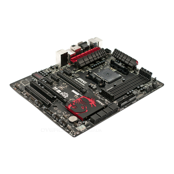
Chapter 1 Getting Started Thank you for choosing the A88X-G45 GAMING Series (MS-7900 v1.X) ATX motherboard. The A88X-G45 GAMING Series motherboards are based on AMD A88X chipset for optimal system efficiency. Designed to fit the ® advanced AMD FM2+/ FM2 processor, the A88X-G45 GAMING Series ®... -
Page 16: Packing Contents
* These pictures are for reference only and may vary without notice. * The packing contents may vary according to the model you purchased. * If you need to purchase the optional accessories or request part numbers, please visit the MSI website at http://www.msi.com/index.php or consult the dealer. Getting Started... -
Page 17: Assembly Precautions
Assembly Precautions ■ The components included in this package are prone to damage from electrostatic discharge (ESD). Please adhere to the following instructions to ensure successful computer assembly. ■ Always turn off the power supply and unplug the power cord from the power outlet before installing or removing any computer component. -
Page 18: Motherboard Specifications
Motherboard Specifications ■ AMD Socket FM2+/ FM2 A-Series/Athlon™ Processors Support Chipset ■ AMD A88X Memory ■ 4x DDR3 memory slots supporting up to 32GB ■ Supports DDR3 2400 (OC)/ 2133/ 1866/ 1600/ 1333 MHz Support ■ Dual channel memory architecture ■... - Page 19 Back Panel ■ 1x PS/2 keyboard/ mouse combo port ■ 2x USB 2.0 ports Connectors ■ 6x USB 3.0 ports ■ 1x VGA port ■ 1x DVI-D port ■ 1x HDMI port ■ 1x DisplayPort ■ 1x Optical S/PDIF-Out connector ■...
- Page 20 Trend Micro SafeSync Form ■ ATX Form Factor ■ 12 in. x 9.6 in. (30.5 cm x 24.4 cm) Factor For the latest information about CPU, please visit http://www.msi.com/service/cpu-support/ For more information on compatible components, please visit http://www.msi.com/service/test-report/ Getting Started...
-
Page 21: Connectors Quick Guide
Connectors Quick Guide DIMM4 JPWR2 DIMM3 SYSFAN3 DIMM2 DIMM1 OC_SWITCH1 SYSFAN1 CPUFAN APU Socket POWER1 RESET1 SLOW_MODE Back Panel JPWR1 PCI_E1 SATA7_8 PCI_E2 SATA5_6 PCI_E3 SATA3_4 PCI_E4 SATA1_2 PCI_E5 JBAT1 SYSFAN2 PCI1 POST1~2 PCI_E6 JFP2 CLR_CMOS1 JCI1 JCOM1 JFP1 JTPM1 JUSB1 SYSFAN4 JUSB2... - Page 22 Connectors Reference Guide Port Name Port Type Page FM2+/ FM2 Socket 1-12 Back Panel I/O Ports CPUFAN,SYSFAN1~3 Fan Power Connectors 1-22 JAUD1 Front Panel Audio Connector 1-26 JBAT1 Clear CMOS Jumper 1-27 JCI1 Chassis Intrusion Connector 1-25 JCOM1 Serial Port Connector 1-26 JFP1, JFP2 System Panel Connectors...
-
Page 23: Back Panel Quick Guide
Back Panel Quick Guide Optical USB 3.0 Port PS/2 Keyboard/ S/PDIF-Out VGA Port LAN Port Mouse combo Port Line-In RS-Out HDMI Port Line-Out CS-Out USB 2.0 Port DVI-D Port DisplayPort USB 3.0 Port SS-Out ▶ PS/2 Keyboard/ Mouse combo Port The PS/2 keyboard/ mouse DIN connector for PS/2 keyboard/ mouse. - Page 24 Important This platform supports dual-display and triple-display function. VGA + DVI-D / VGA + HDMI / VGA + DVI-D + HDMI / DVI-D + HDMI / DVI-D + HDMI + DisplayPort DVI-D + DisplayPort / HDMI + DisplayPort Extend mode ◯...
-
Page 25: Apu (Accelerated Processing Units)
This motherboard is designed to support overclocking. Before attempting to overclock, please make sure that all other system components can tolerate overclocking. Any attempt to operate beyond product specifications is not recommend. MSI does not guarantee the damages or risks caused by inadequate operation beyond product specifications. -
Page 26: Apu & Cooler Installation
APU & Cooler Installation When you are installing the APU, make sure the APU has a cooler attached on the top to prevent overheating. Meanwhile, do not forget to apply some thermal paste on APU before installing the heat sink/cooler fan for better heat dispersion. Follow the steps below to install the APU &... - Page 27 5. Locate the APU fan connector on the motherboard. 6. Position the cooling set onto the retention mechanism. Hook one end of the clip to hook first. APU fan connector 7. Then press down the other end of the clip to fasten the cooling set on the top of the retention mechanism.
-
Page 28: Memory
Memory These DIMM slots are used for installing memory modules. For more information on compatible components, please visit http://www.msi.com/service/test-report/ DIMM1 DIMM2 DIMM3 DIMM4 Video Demonstration Watch the video to learn how to install memories at the address below. http://youtu.be/76yLtJaKlCQ Dual-Channel mode Population Rule In Dual-Channel mode, the memory modules can transmit and receive data with two data bus channels simultaneously. -
Page 29: Mounting Screw Holes
Mounting Screw Holes When installing the motherboard, first install the necessary mounting stands required for an motherboard on the mounting plate in your computer case. If there is an I/O back plate that came with the computer case, please replace it with the I/O backplate that came with the motherboard package. -
Page 30: Power Supply
Power Supply Video Demonstration Watch the video to learn how to install power supply connectors. http://youtu.be/gkDYyR_83I4 JPWR1~2: ATX Power Connectors These connectors allow you to connect an ATX power supply. To connect the ATX power supply, align the power supply cable with the connector and firmly press the cable into the connector. -
Page 31: Expansion Slots
Expansion Slots This motherboard contains numerous slots for expansion cards, such as discrete graphics or audio cards. PCI_E1~6: PCIe Expansion Slots The PCIe slot supports the PCIe interface expansion card. PCIe x16 Slot PCIe x16 Slot PCIe 2.0 x1 Slot PCI1: PCI Slot The PCI slot supports additional LAN, SCSI, USB, and other add-on cards that comply with PCI specifications. -
Page 32: Video/ Graphics Cards
Adding on one or more discrete video cards will significantly boost the system’s graphics performance. For best compatibility, MSI graphics cards are recommended. Video Demonstration Watch the video to learn how to install a graphics card on PCIe x16 slot with butterfly lock. -
Page 33: Amd Crossfire™ (Multi-Gpu) Technology
Important Please ensure that all graphics cards used in CrossFire™ mode are of the same • brand and specifications. For best compatibility with the motherboard, MSI graphics cards are recommended. • Make sure to connect an adequate power supply to the power connectors on the graphics cards to ensure stable operation. - Page 34 Boot up the computer and install the drivers and software included in your video card package. For more information, please refer to the manual that came with your video card. After all of the hardware and software has been properly installed, reboot the system.
-
Page 35: Internal Connectors
Internal Connectors SATA1~8: SATA Connectors This connector is a high-speed SATA interface port. Each connector can connect to one SATA device. SATA devices include disk drives (HDD), solid state drives (SSD), and optical drives (CD/ DVD/ Blu-Ray). Video Demonstration Watch the video to learn how to Install SATA HDD. http://youtu.be/RZsMpqxythc SATA8 SATA6... -
Page 36: Cpufan,Sysfan1~3: Fan Power Connectors
CPUFAN,SYSFAN1~3: Fan Power Connectors The fan power connectors support system cooling fans with +12V. If the motherboard has a System Hardware Monitor chipset on-board, you must use a specially designed fan with a speed sensor to take advantage of the CPU fan control. Remember to connect all system fans. -
Page 37: Jfp1, Jfp2: System Panel Connectors
JFP1, JFP2: System Panel Connectors These connectors connect to the front panel switches and LEDs. When installing the front panel connectors, please use the optional M-Connector to simplify installation. Plug all the wires from the computer case into the M-Connector and then plug the M- Connector into the motherboard. -
Page 38: Jusb1~3: Usb 2.0 Expansion Connectors
JUSB1~3: USB 2.0 Expansion Connectors This connector is designed for connecting high-speed USB peripherals such as USB HDDs, digital cameras, MP3 players, printers, modems, and many others. Important Note that the VCC and GND pins must be connected correctly to avoid possible damage. -
Page 39: Jci1: Chassis Intrusion Connector
JCI1: Chassis Intrusion Connector This connector connects to the chassis intrusion switch cable. If the computer case is opened, the chassis intrusion mechanism will be activated. The system will record this intrusion and a warning message will flash on screen. To clear the warning, you must enter the BIOS utility and clear the record. -
Page 40: Jcom1: Serial Port Connector
JCOM1: Serial Port Connector This connector is a 16550A high speed communication port that sends/receives 16 bytes FIFOs. You can attach a serial device. JAUD1: Front Panel Audio Connector This connector allows you to connect the front audio panel located on your computer case. -
Page 41: Jumper
Jumper JBAT1: Clear CMOS Jumper There is CMOS RAM onboard that is external powered from a battery located on the motherboard to save system configuration data. With the CMOS RAM, the system can automatically boot into the operating system (OS) every time it is turned on. If you want to clear the system configuration, set the jumpers to clear the CMOS RAM. -
Page 42: Voltage Checkpoints
Voltage Checkpoints These voltage checkpoints are used to measure the current system voltages. A multimeter (not included) will be required to check voltages. V-Check Spots These voltage check spots are for you to measure CPU and PCH voltages. To check the voltage, please attach the positive lead of the multimeter to these spots and the negative lead to any ground spot. -
Page 43: Buttons & Switches
BIOS section of the manual for instructions on how to turn off OC Genie from the BIOS. • The usage of OC Genie is at the user’s own risk. Overclocking is never guaranteed by MSI. • To ensure successfully OC Genie usage, MSI components are recommended. 1-29 Getting Started... -
Page 44: Power1: Power Button
POWER1: Power Button This button is used to turn-on and turn-off the system. Press the button once to turn-on or turn-off the system. RESET1: Reset Button This reset button is used to reset the system. Press the button to reset the system. Getting Started 1-30... -
Page 45: Oc_Switch1: Oc Genie Mode Switch
OC_SWITCH1: OC Genie Mode Switch This swtich provides two overclocking modes (Gear 1 and Gear 2) for OC Genie operation. When you press the OC Genie button, the overclocking procedure will be performed according to the setting of this switch. The Gear 1 mode is the default setting. -
Page 46: Led Status Indicators
LED Status Indicators OC Genie Mode LEDs 2-Digit Debug Code LED OC Genie Mode LEDs These LEDs are used to indicate OC Genie operation mode. When the bottom LED lights blue, the OC Genie operation mode is Gear 1. When the top LED lights red, the OC Genie operation mode is Gear 2. Getting Started 1-32... -
Page 47: Debug Code Led Table
Debug Code LED Table Please refer to the table below to get more information about the Debug Code LED message. Post Status 02,07 Power on CPU Initialization 03,08 Power on North Bridge Initialization 04,09 Power on South Bridge Initialization Power on Cache Initialization 11~14,32~36,56~5A Early CPU Initialization 15~18,37~3A... -
Page 48: Drivers And Utilities
After you install the operating system you will need to install drivers to maximize the performance of the new computer you just built. MSI mainbaord comes with a Driver Disc. Drivers allow the computer to utilize your motherboard more efficiently and take advantage of any special features we provide. - Page 49 Chapter 2 Quick Installation This chapter provides demonstration diagrams about how to install your computer. Some of the installations also provide video demonstrations. Please link to the URL to watch it with the web browser on your phone or tablet. You may have even link to the URL by scanning the QR code. Important The diagrams in this chapter are for reference only and may vary from the product you purchased.
- Page 50 APU Installation Quick Installation...
-
Page 51: Chapter 2 Quick Installation
Quick Installation... -
Page 52: Memory Installation
Memory Installation http://youtu.be/76yLtJaKlCQ Quick Installation... -
Page 53: Motherboard Installation
Motherboard Installation Quick Installation... - Page 54 Quick Installation...
-
Page 55: Power Connectors Installation
Power Connectors Installation http://youtu.be/gkDYyR_83I4 Quick Installation... - Page 56 Quick Installation...
-
Page 57: Sata Hdd Installation
SATA HDD Installation http://youtu.be/RZsMpqxythc Quick Installation... -
Page 58: Msata Ssd Installation
mSATA SSD Installation Quick Installation 2-10... -
Page 59: Front Panel Connector Installation
Front Panel Connector Installation JFP1 Connector Installation http://youtu.be/DPELIdVNZUI Front Panel Audio Connector Installation 2-11 Quick Installation... -
Page 60: Peripheral Connector Installation
Peripheral Connector Installation USB2.0 Connector Installation USB3.0 Connector Installation Quick Installation 2-12... -
Page 61: Graphics Card Installation
Graphics Card Installation http://youtu.be/mG0GZpr9w_A 2-13 Quick Installation... - Page 62 Quick Installation 2-14...
- Page 63 Chapter 3 BIOS Setup CLICK BIOS is a revolutionary UEFI interface that allows you to setup and configure your system for optimum use. Using your mouse and keyboard, users can change BIOS settings, monitor CPU temperature, select the boot device priority and view system information such as the CPU name, DRAM capacity, the OS version and the BIOS version.
-
Page 64: Entering Bios Setup
(optional) on the motherboard to enable the system going to BIOS setup directly at next boot. Click "GO2BIOS" tab on "MSI Fast Boot" utility screen. Important Please be sure to install the “MSI Fast Boot” utility before using it to enter the BIOS setup. BIOS Setup... -
Page 65: Overview
Overview After entering BIOS, the following screen is displayed. Temperature monitor Language System information Model name Virtual OC Genie Button Boot device priority bar BIOS menu selection BIOS menu selection Menu display ▶ Temperature monitor Shows the temperatures of the processor and the motherboard. ▶... -
Page 66: Chapter 3 Bios Setup
Virtual OC Genie Button Enables or disables the OC Genie function by clicking on this button. When enabled, this button will be light. Enabling OC Genie function can automatically overclock with MSI optimized overclocking profile. ▶ Model Name Shows the model name of motherboard. -
Page 67: Operation
Operation You can control BIOS settings with the mouse and the keyboard. The following table lists and describes the hot keys and the mouse operations. Hot key Mouse Description <↑↓→← > Select Item Move the cursor <Enter> Select Icon/ Field Click/ Double-click the left button <Esc>... -
Page 68: Settings
SETTINGS System Status ▶ System Date Sets the system date. Use tab key to switch between date elements. The format is <day> <month> <date> <year>. <day> Day of the week, from Sun to Sat, determined by BIOS. Read-only. <month> The month from Jan. through Dec. <date>... -
Page 69: Advanced
Advanced ▶ PCI Subsystem Settings Sets PCI Express interface protocol and latency timer. Press <Enter> to enter the sub-menu. ▶ PCI Latency Timer [32] Sets latency timer of PCI interface device. [Options: 32, 64, 96, 128, 160, 192, 224, 248 PCI Bus clocks] ▶... - Page 70 ▶ SATA Mode [AHCI Mode] Sets the operation mode of the onboard SATA controller. The default mode is AHCI. [Disabled] Disables the SATA function. [IDE Mode] Specify the IDE mode for SATA storage devices. [AHCI Mode] Specify the AHCI mode for SATA storage devices. AHCI (Advanced Host Controller Interface) offers some advanced features to enhance the speed and performance of SATA storage device, such as Native Command Queuing (NCQ) and hot-plugging.
- Page 71 ▶ USB Configuration Sets the onboard USB controller and device function. Press <Enter> to enter the sub- menu. ▶ USB Controller [Enabled] Enables or disables the onboard USB controller. ▶ XHCI Hand-off [Enabled] Enables or disables XHCI hand-off support for the operating system without XHCI hand-off feature.
- Page 72 Disables this function. ▶ MSI Fast Boot [Disabled] MSI Fast Boot is the fastest way to boot the system. It will disable more devices to speed up system boot time which is faster than the boot time of “Fast Boot” . [Enabled] Enables the MSI Fast Boot function to speed up booting time.
- Page 73 ▶ Secure Boot Mode [Standard] Selects the secure boot mode. This item is to select how the secure boot keys be loaded. This item appears when "Secure Boot" is enabled. [Standard] The system will automatically load the secure keys from BIOS. [Custom] Allows user to configure the secure boot settings and manually load the secure keys.
-
Page 74: Boot
▶ Resume From S3/S4/S5 by PS/2 Keyboard [Disabled] Disables or enables the system wake up by PS/2 keyboard. [Any Key] Enables the system to be awakened from S3/ S4/ S5 state when activity of any key on PS/2 keyboard is detected. [Hot Key] Enables the system to be awakened from S3/ S4/ S5 state when activity of hot key on PS/2 keyboard is detected. -
Page 75: Save & Exit
▶ U-Key [Disabled] Enables or disables U-Key as user's password to access the system. ▶ Make U-Key at Makes a key at the USB flash drive to prevent other people from accessing the system. Only the user who has the key with the flash drive can access the system. ▶... - Page 76 Important • Overclocking your PC manually is only recommended for advanced users. • Overclocking is not guaranteed, and if done improperly, can void your warranty or severely damage your hardware. • If you are unfamiliar with overclocking, we advise you to use OC Genie for easy overclocking.
- Page 77 Enables the OC Genie function by virtual button in BIOS or physical button on motherboard. Enabling OC Genie function can automatically overclock the system with MSI optimized overclocking profile. [By BIOS Options] OC Genie function is enabled by clicking the virtual OC Genie button at the top left corner of BIOS setup screen.
- Page 78 ▶ Intel Extreme Memory Profile (XMP) [Disabled] X.M.P. (Extreme Memory Profile) is the overclocking technology by memory module. This item will be available when you install the memory modules that support X.M.P. technology. When the Intel Extreme Memory Profile (XMP) is Enabled, the AMD Memory Profile (AMP) will be forced to be disabled.
- Page 79 ▶ CPU Memory Changed Detect [Enabled] Enables or disables the system to issue a warning message during boot when the CPU or memory has been replaced. [Enabled] The system will issue a warning message during boot and than needs to load the default settings for new devices. [Disabled] Disables this function and keeps the current BIOS settings.
- Page 80 ▶ SVM Mode [Enabled] Enables or disables CPU Virtualization. [Enabled] Enables CPU Virtualization and allows a platform to run multiple operating systems in independent partitions. The system can function as multiple systems virtually. [Disabled] Disables this function. ▶ Core C6 State [Disabled] Enables or disables C6 state support.
-
Page 81: M-Flash
M-FLASH Important M-Flash funcion allows you to update BIOS from USB flash disk (FAT32/ NTFS format only), or allows the system to boot from the BIOS file inside USB flash disk (FAT/ FAT32 format only). ▶ Save BIOS to storage Saves the current BIOS file to the USB flash disk. -
Page 82: Oc Profile
OC PROFILE ▶ Overclocking Profile 1/ 2/ 3/ 4/ 5/ 6 Overclocking Profile 1/ 2/ 3/ 4/ 5/ 6 management. Press <Enter> to enter the sub- menu. ▶ Set Name for Overclocking Profile 1/ 2/ 3/ 4/ 5/ 6 Names the current overclocking profile. ▶... -
Page 83: Hardware Monitor
HARDWARE MONITOR Current Temperature & Temperature & Speed Speed information graphic display control field Voltage display ▶ Current Temperature & Speed information Shows the current CPU temperature, system temperature and fans' speeds. ▶ Temperature & Speed graphic display The red graph shows the minimum and maximum temperatures that be set on the “Fan control field”. - Page 84 Please follow the description below to set the temperatures and fan speeds. ■ a - Selects a fan you want to specify the speed. ■ b - Checks this item to activate the following items for changing default values. ■ c - Slides the Min and Max tabs to set the minimum and maximum temperatures.
-
Page 85: Appendix A Realtek Audio
Appendix A Realtek Audio The Realtek audio provides 10-channel DAC that simultaneously supports 7.1 sound playback and 2 channels of independent stereo sound output (multiple streaming) through the Front-Out-Left and Front-Out-Right channels. -
Page 86: Software Configuration
Software Configuration After installing the audio driver (see Chapter 1 - Driver and Utilities), the “Realtek HD Audio Manager” icon will appear at the notification area (lower right of the screen). You may double click the icon and the GUI will pop up accordingly. double click the icon It is also available to enable the audio driver by clicking the Realtek HD Audio Manager from the Control Panel. -
Page 87: Auto Popup Dialog
▶ Device Selection Here you can select a audio output source to change the related options. The “check” sign (in orange) indicates the devices as default. ▶ Volume Adjustment You can control the volume or balance the right/left side of the speakers that you plugged in front or rear panel by adjust the bar. -
Page 88: Hardware Default Setting
Hardware Default Setting The following diagrams are audio back panel default setting. ■ Backpanel audio jacks to 2-channel speakers diagram F r o ■ Backpanel audio jacks to 4-channel speakers diagram F r o R e a Realtek Audio... - Page 89 ■ Backpanel audio jacks to 6-channel speakers diagram F r o C e n R e a t e r & S u b w o o f ■ Backpanel audio jacks to 8-channel speakers diagram F r o C e n R e a t e r &...
-
Page 91: Appendix B Amd Raid
Appendix B AMD RAID This appendix will assist users in configuring and enabling RAID functionality. -
Page 92: Introduction
Introduction The motherboard comes with the AMD RAID controller that allows you to configure SATA hard drives as RAID sets. AMD RAID controller offers RAID level 0 (Striping), RAID level 1 (Mirroring and Duplexing), RAID level 5 (Block Interleaved Distributed Parity), RAID level 10 (A Stripe of Mirrors) , Volume (JBOD) and RAIDABLE. -
Page 93: Using Amd Raid Controller Bios Configuration Utility
Using AMD RAID Controller BIOS Configuration Utility When booting the system, press <Ctrl + R> when the BIOS banner displays. After entering AMD RAID Controller BIOS Configuration Utility, the following screen is displayed. AMD-RAID Array Configuration Creates an array from the connected disks Arrays Disks 1----RAID5, 999GB, Ready(R/W) -
Page 94: Initialize Disks
Initialize Disks New disks and legacy disks must be initialized before they can be used to create an AMD-RAID array. Initialization writes AMD-RAID configuration information (metadata) to a disk. Important • If a disk is part of an AMD-RAID array, the disk cannot be selected for initialization. To initialize the disk anyway, delete the AMD-RAID array. -
Page 95: Create Arrays
Create Arrays Arrays can be created after the disks are initialized. Important • For redundant arrays, the Create process is not finished until after the operating system and AMD-RAID OS drivers have been installed and the system has booted to the operating system. However, the arrays are immediately available to use for either a bootable array or a data array. -
Page 96: Delete Arrays
Delete Arrays Important Deleting an array permanently destroys all data that is on the array. This action cannot be undone and it is very unlikely the data can be recovered. To delete an array: At the “Main Menu”, use the arrow keys to highlight “Delete Array” and press <Enter>. -
Page 97: Swap Arrays
Swap Arrays Use the Swap Two Arrays option to arrange arrays in a different order. Important If more than one array is created, install the operating system to any of them. However, a small amount of boot information is always written to a disk(s) in the first array (Array 1) of the Array section, regardless on which array the operating system is installed. -
Page 98: Manage Spares
Manage Spares This option allows the user to assign or unassign global or dedicated spares. At the Main Menu, use the <arrow keys> to highlight “Manage Host Spare(s)” and press <Enter> to enter submenu. AMD-RAID Array Configuration Assign Global Hot Spare(s) Arrays Disks 1----RAID0, 999GB, Normal(R/W) -
Page 99: Change The Controller Options
Change the Controller Options Controller Options allows the user to configure options for the boot sequence. At the Main Menu, use the <arrow keys> to highlight “Controller Options” and press <Enter> to enter submenu. AMD-RAID Array Configuration Toggles whether BIOS installs INT13 support Arrays Disks 1----RAID0, 999GB, Normal(R/W) -
Page 100: Change The Staggered Spinup Count
Change the Staggered Spinup Count Depending on a system’s power supply load-rating, you might want to limit the number of disks that are spun-up together when a system is powered on. At the Controller Options submenu, use the <arrow keys> to highlight “Set Staggered Spinup Count ”... -
Page 101: Installing Driver
Important Please follow the instruction below to make an “AMD RAID Driver” for yourself. ® • Insert the MSI Driver Disc into the optical drive. • Click the “Browse CD” on the Setup screen. Copy all the contents in •... -
Page 102: Installing Os On 2.2Tb Raid
RAID 0 volume greater than 2.2TB. 1. Copy \\OtherDriver\Rcadm\rcadm.efi to root of a FAT32 USB Flash Drive from the MSI Driver Disc 2. Plug-in the USB Flash Drive into a USB port on the motherboard. 3. Access BIOS → SETTING → Advanced → Integrated Peripherals submenu. - Page 103 10. Enter “rcadm -C –r0 -d 0 1” to create RAID 0 (“C”=Create a array, “r0”=RAID 0, d 0 1=HDD 0 and HDD 1). If succeeded, you will see a message “created successfully“. fs0:\> rcadm -C -r0 -d 0 1 created successfully 11.