
Related Manuals for Pfaff 2081


Summary of Contents for Pfaff 2081
-
Page 1: Instruction Manual
2081 2083 INSTRUCTION MANUAL This instruction manual applies to machines from the serial number 7 253 910 and software version 0435/002 onwards. 296-12-19 284/002 Instruction Manual engl. 09.15... - Page 2 Internet download, the settings manual can also be ordered as a hard copy under order no. 296-12-19 285/00 . Reprinting, reproduction and/or translation of PFAFF instruction manuals (including parts thereof) is only permitted with our prior agreement and citation of the source.
-
Page 3: Table Of Contents
Technical staff ........................7 Danger warnings ........................8 Proper Use ..........................9 Technical Data ........................10 PFAFF 2081; PFAFF 2083 ....................10 Disposal of the Machine .....................11 Transport, Packaging and Storage ..................12 Transport to the customer’s premises ................. 12 Transport within the customer’s premises ................ - Page 4 Table of Contents Contents ..................Page .01.01 Setting the table height ......................18 .01.02 Inserting the sewing machine into the stand ............... 19 Connecting the plug-in connections and ground cable ............21 Assembling the reel stand ....................22 Initial commissioning ......................23 Switching the machine on / off ....................
-
Page 5: Safety
We warn you expressly that spare parts and accessories that are not supplied by us are also not tested and approved by us. Fitting or using these products may therefore have negative effects on features which depend on the machine design. We are not liable for any damage caused by the use of non-Pfaff parts. -
Page 6: Safety Symbols
Safety Safety symbols Hazard point! Special points of attention. Risk of injury to operating personnel or technical staff! Electric voltage! Danger to operating personnel or technical staff Caution! Do not operate without finger guard and safety covers! Turn off the main switch before threading, changing the bobbin or needle, cleaning, etc.! Special points of attention for the owner-operator ●... -
Page 7: Operating Personnel And Technical Staff
Safety Operating personnel and technical staff Operating personnel .05.01 Operating personnel are persons responsible for equipping, operating and cleaning the machine and for fault clearance in the sewing area. The operating personnel are obligated to comply with the following points: ●... -
Page 8: Danger Warnings
Safety Danger warnings A work area of 1 m must be kept free in front of and behind the machine to ensure unobstructed access at all times. Do not reach into the needle range during the sewing operation! Risk of injury from the needle! Do not allow any objects to be placed on the table during the adjustment work! The objects could become jammed or be slung away! Risk of injury from parts flying around! -
Page 9: Proper Use
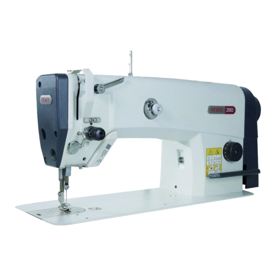
Proper Use Proper Use The PFAFF 2081 is an ultra high-speed, single-needle sewing machine with a needle and drop feed. The PFAFF 2083 is an ultra high-speed, single-needle high-speed seamer with a drop feed. The machines are used for sewing lockstitch seams in the clothing industry. -
Page 10: Technical Data
Technical Data Technical Data PFAFF 2081; PFAFF 2083 Stitch type: ......................301 (lockstitch) Needle system : ............... 134 or 134 KK with subclass -731/01 Design A: ..............for the machining of light-weight materials Design B: ............for the machining of medium-weight materials Design CN: ............ -
Page 11: Disposal Of The Machine
Disposal of the Machine Disposal of the Machine ● It is up to the customer to dispose of the machine properly. ● The materials used for the machine include steel, aluminium, brass and various plastics. The electrical equipment consists of plastics and copper. ●... -
Page 12: Transport, Packaging And Storage
Transport, Packaging and Storage Transport, Packaging and Storage Transport to the customer’s premises All machines are completely packed for delivery. Transport within the customer’s premises The manufacturer assumes no liability for transports within the customer’s premises or to the individual usage sites. Please ensure that the machines are only transported in the vertical position. -
Page 13: Work Symbols
Work Symbols Work Symbols Activities to be performed or important information in this instruction manual are emphasised by symbols. The symbols used have the following meaning: Note, information Cleaning, care Lubrication Maintenance, repairs, adjustment, service work (only to be carried out by technical staff) -
Page 14: Operating Controls
Operating Controls Operating Controls Main switch Before switching on the machine, raise the take-up lever as far as possible. ● Turning the main switch 1 switches the machine on and off. Fig. 7 - 01 Keys on the machine head (only in machines with backtacking system -911/..) ●... -
Page 15: Pedal
Operating Controls Pedal ● With the main switch turned on = Resting position = Sewing = Raise sewing foot (in machines with automatic presser foot lift -910/06) = Trim thread/ (in machines with thread trimmer -900/24) Fig. 7 - 03 Hand lever to raise the sewing foot ●... -
Page 16: Feed Regulator Wheel / Control
Operating Controls Feed regulator wheel / control ● The stitch length can be adjusted by applying pressure and turning the disk 1 simultaneously as desired. ● The key 2 must be pressed for reverse sewing. Fig. 7 - 05 Knee lever ●... -
Page 17: Edge Trimmer -731/01
Operating Controls Edge trimmer -731/01 Do not reach into the blade during operation! Risk of injury! ● Pressing or raising the key 1 switches the edge trimmer on or off. Fig. 7 - 07 Control panel (only in machines with P40 CD) The description can be found in the instruction manual for the drive. -
Page 18: Set-Up And Initial Commissioning
Set-up and Initial Commissioning Set-up and Initial Commissioning The machine may only be set up and commissioned by qualified personnel! All of the relevant safety regulations must always be complied with in this process! If the machine was delivered without a table, then the stand and the table top provided must safely support the weight of the machine and its motor. -
Page 19: Inserting The Sewing Machine Into The Stand
Set-up and Initial Commissioning Inserting the sewing machine into the stand .01.02 Fig. 8 - 02 ● The hinge 1 is screwed to the sewing head base plate. ● Insert the sewing machine into the table top. ● Insert the sewing head support 2 into the table top hole. Do not operate the machine without the support 2! Risk of damage due to the top-heavy sewing head! Machine can tip over backwards when moving it! - Page 20 Set-up and Initial Commissioning Assembling the start inhibitor .01.03 Fig. 8 - 03 ● Insert the machine into the table top, see Chapter 8.01.02 Inserting the sewing machine into the stand ● After loosening the screws 2, adjust the switch 1 in such a way that the switch 1 is actuated when the sewing head is mounted.
-
Page 21: Connecting The Plug-In Connections And Ground Cable
Set-up and Initial Commissioning Connecting the plug-in connections and ground cable Fig. 8 - 04 ● Insert all plugs on the control box 2 in accordance with their designation. ● Insert the "motor" to the bushing E and the bushing M. Caution Inserting the plug incorrectly can damage the control unit! ●... -
Page 22: Assembling The Reel Stand
Set-up and Initial Commissioning Assembling the reel stand ● Assemble the reel stand as shown in the adjacent illustration. ● Then insert the stand into the hole in the table top and secure it with the enclosed nuts. Fig. 8 - 05... -
Page 23: Initial Commissioning
Set-up and Initial Commissioning Initial commissioning ● Remove the plug 1 of the oil reservoir 2 before the initial commissioning. Danger of machine damage! The plug 1 serves solely for tran- sit support and may not be used during the sewing operations. ●... -
Page 24: Set-Up
Set-up Set-up Observe and comply with all regulations and instructions in this instruction manual. Pay particular attention to all safety regulations! All set-up work may only be carried out by appropriately instructed personnel. Disconnect the machine from the electricity mains for all set-up work by operating the main switch or by removing the mains plug! Inserting the needle Switch off the machine! -
Page 25: Winding The Bobbin Thread, Adjusting The Thread Tension
Set-up Winding the bobbin thread, adjusting the thread tension Fig. 9 -02 ● Fit the empty bobbin 1 onto the bobbin winder spindle 2 with the rest thread chamber on the outside. ● Thread in the thread as shown in Fig. 9 - 02 and wind it round the bobbin 1 a few times in an anti-clockwise direction. -
Page 26: Removing / Inserting The Bobbin Case
Set-up Removing / inserting the bobbin case Switch off the machine! Risk of injury due to accidental machine start-up! Removing the bobbin case: ● Tilt the machine backwards. ● Raise the lever 1 and remove the bobbin case 2. Inserting the bobbin case: ●... -
Page 27: Threading The Needle Thread / Adjusting The Needle Thread Tension
Set-up Threading the needle thread / adjusting the needle thread tension Fig. 9 - 06 Switch off the machine! Risk of injury due to accidental machine start-up! ● Thread the needle thread as shown in Fig. 9 - 06. Please ensure that the needle is threaded from the left. -
Page 28: Maintenance And Care
Maintenance and Care Maintenance and Care Maintenance intervals Cleaning ............daily, several times if in continuous operation Clean the hook area ........daily, several times if in continuous operation Check oil level ..................daily, before start-up Lubricate the bevel gears ..................once as year Oil the edge trimmer -731/01 .... -
Page 29: Topping Up The Oil Tank
/s at 40 °C and a density of 0.865 g/cm at 15 °C. We recommend PFAFF sewing machine oil part no. 280-1-120 144. Oiling the edge trimmer -731/01 ● Apply oil to the oil sponge 1 once a week through the hole 2. -
Page 30: Parameter Settings
Maintenance and Care Parameter settings Parameter settings are described in the separate parameter list for the drive and may only be changed by qualified technicians. -
Page 31: Table Top
Table top cutout Table top Table top cutout... -
Page 32: Table Top Assembly
Table top assembly Table top assembly 102,5 102,5 Gestell / Stand Erdung / grounding Kabelkanal / cable duct 30 x 220 Gestell / Stand... -
Page 33: Wearing Parts
Subclass -731/.. 91-701 179-15 (2x) 11-330 958-15 System 134 System 134 KK (-731/..) 11-108 174-25 11-330 085-15 PFAFF 2081-D; 2083-D ( B ) PFAFF 2081; 2083 (A ; B) 91-262 250-91 91-264 300-91 91-262 376-91 91-262 377-91 91-262 437-05 99-137 190-05 (3x) - Page 34 Wearing Parts 99-137 151-45 91-171 049-05 91-171 042-05 95-774 464-25 91-700 996-15 PFAFF 2081; 2083 ( C ) 91-264 383-91 Subclass -731/.. Subclass Trimming margin Part number -731/01-8/11 4.0; 4.5 91-069 595-04/002 -731/01-8/11 5.0 mm 91-169 395-04/002 -731/01-8/11 6.0; 7 .0...
- Page 35 Notes...
- Page 36 PFAFF Industriesysteme und Maschinen GmbH Hans-Geiger-Str. 12 - IG Nord D-67661 Kaiserslautern Telefon: +49 - 6301 3205-0 Telefax: +49 - 6301 3205-1386 E-mail: info@pfaff-industrial.com Gedruckt in der BRD / Printed in Germany / Imprimé en la R.F.A. / Impreso en la R.F.A...