Table of Contents
Advertisement
OUTDOOR UNIT
SERVICE MANUAL
Wireless type
Models
MUZ-FD09NA
MUZ-FD09NA-
MUZ-FD12NA
MUZ-FD12NA-
NOTE:
RoHS compliant products have <G> mark on the spec name plate.
U1
U1
CONTENTS
1. TECHNICAL CHANGES ··································· 3
2. PART NAMES AND FUNCTIONS ····················· 3
3. SPECIFICATION ················································ 4
4. OUTLINES AND DIMENSIONS ························ 6
5. WIRING DIAGRAM ············································ 7
6. REFRIGERANT SYSTEM DIAGRAM ··············· 8
7. DATA ·································································· 9
8. ACTUATOR CONTROL ··································· 15
9. SERVICE FUNCTIONS ··································· 16
10. TROUBLESHOOTING ····································· 16
11. DISASSEMBLY INSTRUCTIONS ···················· 32
PARTS CATALOG (OBB498)
• 3. SPECIFICATION has been corrected.
Please void OBH498.
No. OBH498
HFC
REVISED EDITION-A
utilized
R410A
Indoor unit service manual
MSZ-FD•NA Series (OBH497)
TM
Advertisement
Table of Contents
Troubleshooting

Related Manuals for Mitsubishi Electric Mr.Slim MUZ-FD09NA


Summary of Contents for Mitsubishi Electric Mr.Slim MUZ-FD09NA
-
Page 1: Table Of Contents
OUTDOOR UNIT SERVICE MANUAL Wireless type Models MUZ-FD09NA MUZ-FD09NA- MUZ-FD12NA MUZ-FD12NA- NOTE: RoHS compliant products have <G> mark on the spec name plate. Revision A: • 3. SPECIFICATION has been corrected. Please void OBH498. utilized R410A MSZ-FD•NA Series (OBH497) CONTENTS 1. -
Page 2: Revision A
Revision A: • 3. SPECIFICATION has been corrected. -
Page 3: Technical Changes
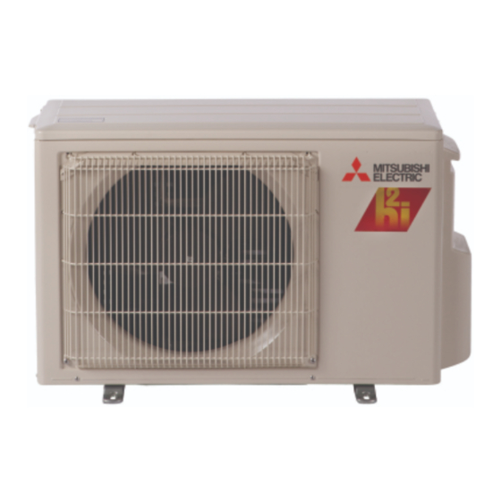
TECHNICAL CHANGES MUZ-FD09NA MUZ-FD09NA - MUZ-FD12NA MUZ-FD12NA - 1. New model PART NAMES AND FUNCTIONS MUZ-FD09NA MUZ-FD12NA Air inlet Piping Drain hose Air outlet Drain outlet... -
Page 4: Specification
1 : Rating conditions (Cooling) — Indoor : 80˚FDB, 67˚FWB, Outdoor : 95˚FDB, (75˚FWB) Rated frequency (Heating) — Indoor : 70˚FDB, 60˚FWB, Outdoor : 47˚FDB, 43˚FWB (Heating) — Indoor : 70˚FDB, 60˚FWB, Outdoor : 17˚FDB, 15˚FWB MUZ-FD09NA Btu/h 9,000 (2,800~9,000) - Page 5 Test condition 3, 4 Mode Test "A" Cooling Steady State at rated compressor Speed "B-2" Cooling Steady State at rated compressor Speed SEER "B-1" Cooling Steady State (Cooling) at minimum compressor Speed Low ambient Cooling Steady State at minimum compressor Speed Intermediate Cooling Steady State at Intermediate compressor Speed 5 Standard Rating-Heating...
-
Page 6: Outlines And Dimensions
OUTLINES AND DIMENSIONS MUZ-FD09NA MUZ-FD12NA 15-3/4 Drain hole Air in Air in Air out handle 11-29/32 5-15/16 19-11/16 31-1/2 REQUIRED SPACE 1-5/8 1-9/16 2- 3/8 13/16 Oval hole 29/32 11-1/4 6-23/32 2-23/32 Basically open 4 inch or more without any obstruction in front and on both sides of the unit. -
Page 7: Wiring Diagram
WIRING DIAGRAM MUZ-FD09NA MUZ-FD12NA... -
Page 8: Refrigerant System Diagram
REFRIGERANT SYSTEM DIAGRAM MUZ-FD09NA MUZ-FD12NA Refrigerant pipe ø3/8 (with heat insulator) Flared connection Flared connection Refrigerant pipe 1/4 (with heat insulator) MAX. REFRIGERANT PIPING LENGTH and MAX. HEIGHT DIFFERENCE Model Max. Length MUZ-FD09NA MUZ-FD12NA Indoor unit Max. Height difference ADDITIONAL REFRIGERANT CHARGE (R410A : oz.) NOTE : Refrigerant piping exceeding 25 ft. -
Page 9: Data
How to operate with fixed operational frequency of the compressor. 1. Press the EMERGENCY OPERATION switch on the front of the indoor unit, and select either EMERGENCY COOL mode or EMERGENCY HEAT mode before starting to operate the air conditioner. 2. The compressor starts with operational frequency. - Page 10 7-2. PERFORMANCE CURVE Cooling MUZ-FD09NA SHF at rating condition = 0.76 Airflow = 307 CFM Outdoor intake air DB temperature (°F) Heating MUZ-FD09NA Airflow = 381 CFM Outdoor intake air WB temperature (°F) This value of frequency is not the same as the actual frequency in operating. Refer to 7-5 and 7-6 for the relationships between frequency and capacity.
- Page 11 7-3. CONDENSING PRESSURE Cooling Data is based on the condition of indoor humidity 50 %. Air flow should be set to High speed. MUZ-FD09NA (PSIG) 68 70 Outdoor ambient temperature MUZ-FD12NA (PSIG) 68 70 Outdoor ambient temperature (PSIG) 105(°F) 68 70 (PSIG) 105(°F)
- Page 12 Data is based on the condition of outdoor humidity 75%. Air flow should be set to High speed. Data is for heating operation without any frost. MUZ-FD09NA (PSIG) 20 25 30 35 40 45 50 55 60 65 70 Outdoor ambient temperature...
- Page 13 9,000 10,900 — 0.76 — 0.650 0.750 MSZ-FD09NA phase, 208/230 , 1 , 60 0.018 0.024 0.19/0.17 0.25/0.23 MUZ-FD09NA phase, 208/230 , 1 , 60 0.632 0.726 2.96/2.68 3.39/3.06 0.35/0.32 PSIG PSIG ˚F ˚F ˚F ˚F 2 lb. 9 oz.
- Page 14 7-5. CAPACITY AND INPUT CORRECTION BY INVERTER OUTPUT FREQUENCY MUZ-FD09NA Correction of Cooling capacity (Hz) The operational frequency of compressor The operational frequency of compressor MUZ-FD12NA Correction of Cooling capacity (Hz) The operational frequency of compressor The operational frequency of compressor 7-6.
-
Page 15: Actuator Control
ACTUATOR CONTROL MUZ-FD09NA MUZ-FD12NA 8-1. OUTDOOR FAN MOTOR CONTROL The fan motor turns ON/OFF, interlocking with the compressor. [ON] The fan motor turns ON 5 seconds before the compressor starts up. [OFF] The fan motor turns OFF 15 seconds after the compressor has stopped running. -
Page 16: Service Functions
2. Take care of the following during servicing 1) Before servicing the air conditioner, be sure to turn OFF the main unit first with the remote controller, then after con- firming the horizontal vane is closed, turn off the breaker and/or disconnect the power plug. -
Page 17: Failure Mode Recall Function
10-2. FAILURE MODE RECALL FUNCTION Outline of the function This air conditioner can memorize the abnormal condition which has occurred once. Even though LED indication listed on the troubleshooting check table (10-3.) disappears, the memorized failure details can be recalled. - Page 18 2. Flow chart of the detailed outdoor unit failure mode recall function Operational procedure The outdoor unit might be abnormal. Confi rm if outdoor unit is abnormal according to the following procedures. Confi rm that the remote controller is in the failure mode recall function. With the remote controller headed towards the indoor unit, press TOO COOL or TOO WARM button to adjust the set temperature to 77˚F (25˚C).
- Page 19 3. Outdoor unit failure mode table POWER lamp Abnormal point (Indoor unit) (Failure mode / protection) None (Normal) 2-time fl ash Outdoor power system 2.5 seconds 3-time fl ash Discharge temperature 2.5 seconds thermistor Defrost thermistor Fin temperature thermistor P.C. board temperature thermistor Ambient temperature thermistor...
-
Page 20: Troubleshooting Check Table
10-3. TROUBLESHOOTING CHECK TABLE Abnormal point/ Symptom LED indication Outdoor unit 1-time fl ash every Outdoor power sys- does not oper- 2.5 seconds ate. Outdoor thermistors Discharge temperature thermistor, fi n temperature thermistor, Outdoor control sys- 6-time fl ash Serial signal 2.5 seconds OFF 11-time fl... - Page 21 Abnormal point/ Symptom LED indication Condition Outdoor unit 7-time fl ash Low discharge tem- operates. 2.5 seconds OFF perature protection 8-time fl ash PAM protection 2.5 seconds OFF PAM: Pulse Ampli- tude Modulation 9-time fl ash Inverter check mode The connector of compressor is disconnected, inverter check 2.5 seconds OFF Condition Temperature of discharge temperature thermistor has been...
- Page 22 10-4. TROUBLE CRITERION OF MAIN PARTS MUZ-FD09NA MUZ-FD12NA Part name Defrost thermistor (RT61) Measure the resistance with a tester. Ambient temperature thermistor (RT65) Refer to 10-6. “Test point diagram and voltage”, 1. “Inverter P.C. board”, the chart of thermistor. Outdoor heat ex-...
-
Page 23: Check Of Compressor
10-5. TROUBLESHOOTING FLOW A How to check inverter/compressor Disconnect the connector (CN61) between compressor and the intelligent power module (IPM). Check the voltage between terminals. Are the voltages balanced? Check the compressor. B Check of open phase ●With the connector between the compressor and the intelligent power module disconnected, activate the inverter and check if the inverter is normal by measuring the balance of voltage between the terminals. - Page 24 D Check of compressor winding ●Disconnect the connector (CN61) between the compressor and intelligent power module, and measure the resistance between the compressor terminals. <<Measurement point>> at 3 points BLK-WHT Measure the resistance between the lead wires at 3 points. BLK-RED WHT-RED <<Judgement>>...
- Page 25 G Check of outdoor thermistors Disconnect the connector of thermistor in the outdoor P.C. board (see below table), and measure the resistance of thermistor. Is the thermistor normal? (Refer to 10-6.1.) Reconnect the connector of thermistor. Turn ON the power supply and press EMERGENCY OPERATION switch. Does the unit operate for 10 minutes or more without showing thermistor abnormality? (Cause is poor contact.)
- Page 26 I Check of outdoor fan motor Disconnect CN932 from the inverter P.C. board, and measure the resistance of the outdoor fan motor. Is the outdoor fan motor normal? (Refer to 10-4.) Replace the inverter P.C. board. J Check of power supply Disconnect the connector (CN61) between compressor and intelligent power module.
- Page 27 K Check of LEV (Expansion valve) Turn ON the power supply. <Preparation of the remote controller> While pressing both OPERATION SELECT button and TOO COOL button on the remote controller at the same time, press RESET button. First, release RESET button. And release the other two buttons after all LCD except the set temperature in operation display section of the remote controller is displayed after 3 seconds.
- Page 28 L Check of inverter P.C. board Check the outdoor fan motor. (Refer to10-5. .) Is the fuse (F901) blown on the in- verter P.C. board? Check the connection of the connectors (CN932) of the outdoor fan motor. If the connection is poor, make it correct. Operate the outdoor unit by starting EMERGENCY OPERATION.
- Page 29 M How to check miswiring and serial signal error Press EMERGENCY OPERATION switch once. Does AREA-L lamp light up? <Confi rmation of the power to the indoor unit> Is serial signal error indicated 6 minutes later? • Turn OFF inverter-controlled lighting equipment.
- Page 30 3. Channel, frequency, broadcast station unaffected by the electromagnetic noise 4. Layout of ; indoor/outdoor unit of the air conditioner, indoor/outdoor wiring, grounding wire, antennas, wiring from antennas, receiver 5. Electric fi eld intensity of the broadcast station affected by the electromagnetic noise 6.
- Page 31 10-6. TEST POINT DIAGRAM AND VOLTAGE 1. Inverter P.C. board MUZ-FD09NA MUZ-FD12NA DB61 Back side of unit DC260 ~300 V AC 208/230 V Fuse (F901) 250 V 3.15 A Output to drive com- pressor (LDU, LDV, LDW) Front side of unit...
-
Page 32: Disassembly Instructions
Check the shape of the terminal before detaching. (1) Slide the sleeve and check if there is a locking lever or not. Sleeve Locking lever 11-1. MUZ-FD09NA MUZ-FD12NA OPERATING PROCEDURE 1. Removing the cabinet (1) Remove the screw fixing the service panel. (See Photo 1.) - Page 33 OPERATING PROCEDURE 2. Removing the inverter assembly, inverter P.C. board (1) Remove the cabinet and panels. (Refer to 1.) (2) Disconnect the lead wire to the reactor and the following connectors; <Inverter P.C. board> CN721 (R.V.coil) CN932 (Fan motor) CN641 (Defrost thermistor and discharge temperature ther- mistor) CN643 (Ambient temperature thermistor) CN644 (Outdoor heat exchanger temperature thermistor)
- Page 34 OPERATING PROCEDURE 5. Removing outdoor fan motor (1) Remove the cabinet and panels. (Refer to 1.) (2) Disconnect the connectors for outdoor fan motor. (3) Remove the propeller nut. (See Photo 7.) (4) Remove the propeller. (See Photo 7.) (5) Remove the screws fixing the fan motor. (See Photo 7.) (6) Remove the fan motor.
- Page 36 HEAD OFFICE: TOKYO BLDG., 2-7-3, MARUNOUCHI, CHIYODA-KU, TOKYO 100-8310, JAPAN Copyright 2008 MITSUBISHI ELECTRIC ENGINEERING CO.,LTD Distributed in Mar. 2008. No. OBH498 REVISED EDITION-A 7 Distributed in Jan. 2008. No. OBH498 7 Made in Japan New publication, effective Mar. 2008 Specifications subject to change without notice.