Table of Contents
Advertisement
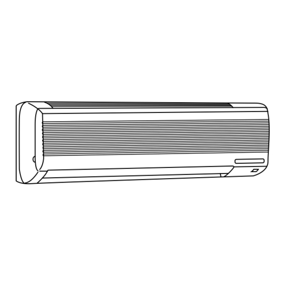
SPLIT-TYPE,HEAT PUMP AIR CONDITIONERS
SERVICE MANUAL
Wireless type
Models
MSH-07NV -
MSH-09NV -
MSH-12NV -
MSH-18NV -
MSH-24NV -
MSH-07NV -
MSH-09NV -
MSH-12NV -
MSH-18NV -
MSH-24NV -
MSH-18NV -
MSH-18NV -
E1
MSH-18NV -
E2
MSH-18NV -
E3
Refer to the Service Manual OB185 when MSH-07/09/12NV-
are connected with MXZ-32NV-
This Servise Manual OB207 deals with MSH-07/09/12/18/24NV-E1,
MUH-07/09/12/18/24NV-E1, MSH-18NV-E2, and MUH-18NV-E2 in
OB176 REVISED EDITION-A issued in July in1997.
Therefore, please refer to OB207, not to OB176 REVISED
EDITION-A, for the above models.
· MUH-07NV -
E1
( WH )
· MUH-09NV -
E1
( WH )
· MUH-12NV -
E1
( WH )
· MUH-18NV -
E1
( WH )
· MUH-24NV -
E1
( WH )
· MUH-07NV -
E2
( WH )
· MUH-09NV -
E2
( WH )
· MUH-12NV -
E2
( WH )
· MUH-18NV -
E2
( WH )
· MUH-24NV -
E2
( WH )
· MUH-18NV -
E3
( WH )
CONTENTS
1. TECHNICAL CHANGES ····································2
2. PART NAMES AND FUNCTIONS······················3
3. SPECIFICATION·················································6
4. OUTLINES AND DIMENSIONS ······················ 11
5. WIRING DIAGRAM ··········································15
6. REFRIGERANT SYSTEM DIAGRAM ··············24
7. PERFORMANCE CURVES ······························29
8. MICROPROCESSOR CONTROL ····················33
9. SERVICE FUNCTIONS ····································44
10. TROUBLESHOOTING······································47
11. DISASSEMBLY INSTRUCTIONS·····················60
12. PARTS LIST······················································70
13. OPTIONAL PARTS ····································BACK
as multi system units.
E1
MSH-07/09/12/18NV-
,
E1
No. OB207
E1
E1
E1
E1
E1
E2
E2
E2
E2
E2
E3
and MSH-18NV-
,
E2
E3
Advertisement
Table of Contents
Troubleshooting

Related Manuals for Mitsubishi Electric MSH-07NV


Summary of Contents for Mitsubishi Electric MSH-07NV
-
Page 1: Service Manual
SPLIT-TYPE,HEAT PUMP AIR CONDITIONERS SERVICE MANUAL Wireless type Models MSH-07NV - MSH-09NV - MSH-12NV - MSH-18NV - MSH-24NV - MSH-07NV - MSH-09NV - MSH-12NV - MSH-18NV - MSH-24NV - MSH-18NV - MSH-18NV - MSH-18NV - MSH-18NV - Refer to the Service Manual OB185 when MSH-07/09/12NV-... -
Page 2: Technical Changes
TECHNICAL CHANGES MSH-17NV - MSH-07NV - 1. Indoor electronic control P.C.board has changed. However, it is compatible between 2. Auto restart function is added. MSH-09NV - MSH-09NV - 1. Indoor electronic control P.C.board has changed. However, it is compatible between 2. -
Page 3: Part Names And Functions
PART NAMES AND FUNCTIONS INDOOR UNIT MSH-07NV - MSH-07NV - MSH-09NV - MSH-09NV - MSH-12NV - MSH-12NV - (When the front panel is open) MSH-07NV - MSH-09NV - MSH-07NV - MSH-09NV - MSH-18NV - MSH-24NV - MSH-24NV - MSH-18NV -... - Page 4 MSH-07NV - MSH-09NV - MSH-12NV - MSH-18NV - MSH-18NV - REMOTE CONTROLLER...
- Page 5 MSH-07NV - (Serial number 7000201T~) MSH-12NV - (Serial number 7000001T~) MSH-07NV - MSH-12NV - MSH-24NV - MSH-09NV - (Serial number 7000201T~) MSH-24NV - MSH-09NV - MSH-18NV - (Serial number 7000001T~) MSH-18NV -...
- Page 6 Refrigerant filling capacity(R-22) Thermistor NOTE:Test conditions Cooling : Indoor DB27°C / WB19°C Outdoor DB35°C / WB24°C Heating : Indoor DB20°C /WB15.5°C Outdoor DB 7°C / WB 6°C MSH-07NV - Cooling Single phase,220-240V,50Hz K /h INDOOR 492 OUTDOOR 1620 3.30-3.20 710-750 — A(kW) 2.80-2.70...
- Page 7 Model Function Power supply Capacity Capacity Dehumidification Air flow Power outlet Running current Power input Auxiliary heater Electrical data Power factor Starting current Compressor motor current Fan motor current Coefficient of performance(C.O.P) Model Compressor Output Winding resistance(at20:) Indoor Model fan motor Winding resistance(at20:) Outdoor Model...
- Page 8 Model Function Power supply Capacity Capacity Dehumidification Air flow Power outlet Running current Power input Auxiliary heater Electrical data Power factor Starting current Compressor motor current Fan motor current Coefficient of performance(C.O.P) Model Compressor Output Winding resistance(at20:) Indoor Model fan motor Winding resistance(at20:) Outdoor Model...
- Page 9 Refrigerant filling capacity(R-22) Thermistor NOTE:Test conditions Cooling : Indoor DB27°C / WB19°C Outdoor DB35°C / WB24°C Heating : Indoor DB20°C /WB15.5°C Outdoor DB 7°C / WB 6°C MSH-07/09/12/18NV- MSH-07NV- E1 E2 Cooling Single phase,220-240V,50Hz — — K /h A(kW) 94-86 "...
- Page 10 Refer to the Service Manual OB185 when MSH-07/09/12NV- connected with MXZ-32NV- as multi system units. Model Function Power supply Capacity Capacity Dehumidification Air flow Power outlet Running current Power input Auxiliary heater Electrical data Power factor Starting current Compressor motor current Fan motor current Coefficient of performance(C.O.P) Model...
-
Page 11: Outlines And Dimensions
OUTLINES AND DIMENSIONS Unit: mm MSH-07NV - MSH-09NV - MSH-07NV - MSH-09NV - INDOOR UNIT MUH-07NV - MUH-09NV - MUH-07NV - MUH-09NV - OUTDOOR UNIT... -
Page 12: Indoor Unit
MSH-12NV - MSH-12NV - INDOOR UNIT MUH-12NV - MUH-12NV - OUTDOOR UNIT If the right/left sides or back side is vacant,the front has only to be 50cm unobstructed. Unit: mm 9.52... - Page 13 MSH-18NV - MSH-24NV - INDOOR UNIT 1015 1015 MUH-18NV - MUH-18NV - OUTDOOR UNIT MSH-18NV - Installation plate Installation plate Air in Air in Air out Air out Power supply cord Power supply cord 17.5 17.5 Lead to right 2m Lead to right 2m Lead to left 1m Lead to left 1m...
- Page 14 MUH-24NV- MUH-24NV- 362(14-1/4) 330(13) 27.5 39.5 850(33-7/16) Unit : mm (inch) max.
-
Page 15: Indoor/Outdoor Unit Wiring Diagram
WIRING DIAGRAM MODELS WIRING DIAGRAM MSH-07NV - MSH-09NV - INDOOR UNIT FOR MULTI SYSTEM 12VDC TO OUTDOOR UNIT CONNECTING NAME SYMBOL INDOOR FAN CAPACITOR FUSE(93:) FUSE(3.15A) INDOOR FAN MOTOR NOTE:1. For the outdoor electric wiring refer to the outdoor unit electric wiring diagram for servicing. - Page 16 MODEL WIRING DIAGRAM MSH-12NV - INDOOR UNIT FOR MULTI SYSTEM 12VDC TO OUTDOOR UNIT CONNECTING SYMBOL NAME INDOOR FAN CAPACITOR FUSE(93:) FUSE(3.15A) INDOOR FAN MOTOR NOTE:1. For the outdoor electric wiring refer to the outdoor unit electric wiring diagram for servicing. 2.
- Page 17 MSH-18NV - MODEL WIRING DIAGRAM INDOOR UNIT NAME SYMBOL INDOOR FAN CAPACITOR FUSE(93:) FUSE(3.15A) INDOOR FAN MOTOR VANE MOTOR NOTE:1. For the outdoor electric wiring refer to the outdoor unit electric wiring diagram for servicing. 2. Use copper conductors only.(For field wiring) 3.
- Page 18 MSH-24NV - MODEL WIRING DIAGRAM INDOOR UNIT 220-240V~ 220-240V~ TO OUTDOOR UNIT CONNECTING POWER SUPPLY CORD ~/N 220-240V 50Hz CIRCUIT BREAKER GRN/YLW SYMBOL NAME INDOOR FAN MOTOR CAPACITOR FUSE(93:) FUSE(3.15A) INDOOR FAN MOTOR VANE MOTOR NOTE:1. For the outdoor electric wiring refer to the outdoor unit electric wiring diagram for servicing. 2.
- Page 19 MSH-07NV - MSH-09NV - INDOOR UNIT TO OUTDOOR UNIT CONNECTING 12VDC 220-240V~ POWER SUPPLY CORD ~/N 220-240V 50Hz CIRCUIT BREAKER FOR MULTI SYSTEM 12VDC TO OUTDOOR UNIT CONNECTING SYMBOL NAME INDOOR FAN MOTOR CAPACITOR FUSE(93:) FUSE(3.15A) INDOOR FAN MOTOR NOTE:1. For the outdoor electric wiring refer to the outdoor unit electric wiring diagram for servicing.
- Page 20 MUH-12NV - MODEL WIRING DIAGRAM OUTDOOR UNIT 12VDC 220-240V~ GRN/YLW SYMBOL NAME SYMBOL COMPRESSOR CAPACITOR FUSE(2A) NR61 COMPRESSOR<INNER THERMOSTAT> RT61 SR61 SOLID STATE RELAY NOTE:1. Use copper conductors only.(For field wiring) 2. Since the indoor and outdoor unit connecting wires have polarity, connect them according to the numbers. 3.
- Page 21 MSH-18NV - MODEL WIRING DIAGRAM INDOOR UNIT FOR MULTI SYSTEM 12VDC TO OUTDOOR UNIT CONNECTING SYMBOL NAME INDOOR FAN CAPACITOR FUSE(93:) FUSE(3.15A) INDOOR FAN MOTOR VANE MOTOR NOTE:1. For the outdoor electric wiring refer to the outdoor unit electric wiring diagram for servicing. 2.
- Page 22 MSH-24NV - MODEL WIRING DIAGRAM INDOOR UNIT 220-240V~ 220-240V~ TO OUTDOOR UNIT CONNECTING POWER SUPPLY CORD ~/N 220-240V 50Hz CIRCUIT BREAKER GRN/YLW SYMBOL NAME INDOOR FAN CAPACITOR FUSE(93:) FUSE(3.15A) INDOOR FAN MOTOR VANE MOTOR NOTE:1. For the outdoor electric wiring refer to the outdoor unit electric wiring diagram for servicing. 2.
- Page 23 MSH-18NV - MODEL WIRING DIAGRAM INDOOR UNIT TO OUTDOOR UNIT CONNECTING 12VDC 220-240V~ POWER SUPPLY CORD ~/N 220-240V 50Hz CIRCUIT BREAKER FOR MULTI SYSTEM TO OUTDOOR UNIT CONNECTING SYMBOL NAME INDOOR FAN CAPACITOR FUSE(93:) FUSE(3.15A) INDOOR FAN MOTOR VANE MOTOR NOTE:1.
-
Page 24: Refrigerant System Diagram
REFRIGERANT SYSTEM DIAGRAM MSH-07NV - MSH-07NV - Refrigerant pipe [ 9.52 INDOOR UNIT (Option) Indoor coil Indoor thermistor heat RT12 exchanger Room temperature thermistor RT11 Refrigerant pipe [6.35 (Option) (with heat insulator) MSH-09NV - MSH-09NV - Refrigerant pipe [9.52 INDOOR UNIT... - Page 25 MSH-12NV - MSH-12NV - Refrigerant pipe [12.7 (Optional) INDOOR UNIT (with heat insulator) Indoor Indoor coil heat thermistor exchanger RT12 Flared connection RT11 Room temperature thermistor RT11 Flared connection Refrigerant pipe (Option) [6.35 (with heat insulator) MSH-18NV - MSH-18NV - MSH-18NV - INDOOR UNIT Refrigerant pipe [15.88...
- Page 26 MSH-24NV - MSH-24NV - INDOOR UNIT Refrigerant pipe [15.88 (Option) (with heat insulator) Indoor coil thermistor Indoor RT12 heat exchanger Distributor Flared connection Room temperature thermistor RT11 Flared connection Refrigerant pipe (Option) [9.52 (with heat insulator) Reversing valve (4- way valve) Muffler Ball valve Accumulator...
- Page 27 MAX. REFRIGERANT PIPING LENGTH Refrigerant piping Models Max. length : m MSH-07NV - MSH-09NV - MSH-07NV - MSH-09NV - MSH-12NV - MSH-12NV - MSH-18NV - MSH-18NV - MSH-18NV - MSH-24NV - MSH-24NV - MAX. HEIGHT DIFFERENCE ADDITIONAL REFRIGERANT CHARGE(R-22 : g)
- Page 28 EVACUATION PROCEDURES(AIR PURGE) Remove the service port cap of the stop valve on the side of the outdoor unit gas pipe.(The stop valve will not work in its initial state fresh out of the factory (totally closed with cap on)) Remove the gage manifold valve quickly from the service port of the stop valve.
-
Page 29: Performance Curves
PERFORMANCE CURVES The standard data contained in these specifications apply only to the operation of the air conditioner under normal conditions, since operating conditions vary according to the areas where these units are installed. The following information has been pro- vided to clarify the operating characteristics of the air conditioner under the conditions indicated by the performance curve. - Page 30 12.0 14.0 11.4 12.7 10.4 11.5 10.3 19.9 25.5 28.7 28.0 28.0 23.5 26.5 25.9 25.9 18.4 16.9 21.6 24.3 23.7 23.7 15.3 19.6 22.5 21.6 21.6 13.8 17.6 19.9 19.4 19.4 12.3 15.6 17.7 17.2 17.2 10.7 13.7 15.5 15.1 15.1 11.7...
- Page 31 MUH-09NV - (kgf/F•G)(MPa•G) 220/240V Ambient temperature(˚C) Ambient humidity(%) MUH-12NV - (kgf/F•G)(MPa•G) 220/240V Ambient temperature(˚C) Ambient humidity(%) MUH-18NV - (kgf/F•G)(MPa•G) 220/240V Ambient temperature(˚C) Ambient humidity(%) MUH-24NV - (kgf/F•G)(MPa•G) 220V Ambient temperature(˚C) Ambient humidity(%) MUH-09NV - Ambient temperature(˚C) Ambient humidity(%) MUH-12NV - Ambient temperature(˚C) Ambient humidity(%) MUH-18NV -...
-
Page 32: Heat Operation
HEAT operation Condition indoor:Dry bulb temperature 20.0°C Wet bulb temperature 14.5°C MUH-07NV - Ambient temperature(˚C) MUH-09NV - Ambient temperature(˚C) Outdoor:Dry bulb temperature 7,15,20°C 220V 240V 220V 240V Wet bulb temperature 6,12,14.5°C MUH-12NV - 220V 240V Ambient temperature(˚C) MUH-18NV - 220V 240V Ambient temperature(˚C) MUH-24NV -... -
Page 33: Microprocessor Control
MICROPROCESSOR CONTROL Wireless remote controller INDOOR UNIT DISPLAY SECTION MSH-07NV - MSH-09NV - MSH-18NV - MSH-24NV - MSH-07NV - MSH-09NV - MSH-18NV - MSH-24NV - Once the controls are set, the same operation mode can be repeated by simply turning the OPERATE/STOP button ON. - Page 34 (4) The initial set temperature is decided by the initial room temperature. Model COOL mode of "I FEEL CONTROL" DRY mode of "I FEEL CONTROL" HEAT mode of "I FEEL CONTROL" 1 After the system restarts by the remote controller, the system operates with the previous set temperature regardless of the initial set temperature.
- Page 35 — COOL mode of “I FEEL CONTROL” — Compressor and outdoor fan motor Indoor fan motor NOTE : Coil frost prevention during COOL mode of “I FEEL CONTROL” There are two types of controls in coil frost prevention. Temperature control <MSH-07/09/12>...
- Page 36 Operation time chart Example Thermostat Indoor fan Outdoor fan compressor 8 min. NOTE Coil frost prevention during DRY mode of “I FEEL CONTROL” The operation is as same as coil frost prevention during COOL mode of “I FEEL CONTROL”. However the indoor fan speed becomes the set speed or Lo. —...
- Page 37 2. High pressure protection During heating operation, the outdoor fan motor is controlled by the indoor coil thermistor RT12 temperature for excess rise protection of compressor discharge pressure. Outdoor fan OFF : 52°C (MSH-07/09/12/24), 50°C (MSH-18) Outdoor fan ON : 48°C (MSH-07/09/12/24), 46°C (MSH-18) High pressure protection time chart Indoor coil thermistor RT12 temperature...
- Page 38 (3) Defrosting time chart Defrost thermistor RT61 3.1: or more -3: or less Outdoor 52C relay(Compressor) (Reversing valve coil) 30 sec. SR61 Outdoor fan Defrost counter Indoor fan Horizontal Indoor vane Set position NOTE1 When the indoor coil thermistor reads above 18°C, indoor fan operates at VLo for 30 seconds. When the indoor coil thermistor reads 18°C or less, the indoor fan stops.
- Page 39 4. Reversing valve control Heating · · · · · ON Cooling · · · · · OFF Dry · · · · · · · · OFF NOTE1: The Reversing valve reverses for 5 seconds right before start-up of the compressor. NOTE2: Refer to the Service Manual OB185 when MSH-07/09/12NV- are connected with MXZ-32NV- Compressor...
- Page 40 8-5. FAN MOTOR CONTROL (1) Rotational frequency feedback control The indoor fan motor is equipped with a rotational frequency sensor, and outputs signal to the microprocessor to feedback the rotational frequency. Comparing the current rotational frequency with the target rotational frequency (Hi,Me,Lo,SLEEP), the microprocessor controls SR11 (MSH-07/09/12), IC141 (MSH-18/24) and adjusts fan motor electric current to make the current rotational frequency close to the target rotational frequency.
- Page 41 (3) Positioning The vane is once pressed to the vane stopper below to confirm the standard position and then set to the desired angle. The positioning is decided as follows. (a) When the OPERATE/STOP button is pressed. (POWER ON/OFF) (b) When the vane control is changed from AUTO to MANUAL. (c) When the SWING is finished.
- Page 42 When setting the ON timer, check that OPERATION INDICATOR lamp of the indoor unit lights. NOTE1 : Be sure to place the remote controller at the position where its signal can reach the air conditioner even during TIMER operation, or the set time may deviate within the range of about 10 minutes.
- Page 43 8-9. EMERGENCY-TEST OPERATION When the remote controller is missing, has failed or the batteries run down, press the EMERGENCY OPERATION switch on the front of the indoor unit. The unit will start and the OPERATION INDICATOR lamp will light. The first 30 minutes of operation will be the test run operation. This operation is for servicing. The indoor fan runs at high speed and the system is in continuous operation.
-
Page 44: Service Functions
In this case, to operate each indoor unit individually by each remote controller, P.C. boards of remote controller must be modified according to the number of the indoor unit. (1)<The reset button can be located on the rear side.> MSH-07NV - MSH-09NV - MSH-18NV - How to modify the remote controller P.C. - Page 45 (2)<The reset button can be located on the front side.> MSH-07NV - (Serial number 7000201T~) MSH-12NV - (Serial number 7000001T~) MSH-07NV - MSH-12NV - MSH-24NV - How to modify the remote controller P.C. board Remove batteries before modification. The board has a print as shown below : The P.C.board has the print “J1”...
- Page 46 5. AUTO RESTART FUNCTION MSH-07NV - MSH-12NV - MSH-18NV - When the indoor unit is controlled with the remote controller, the operation mode, set temperature, and the fan speed are memorized by the indoor electronic control P.C.board. The “AUTO RESTART FUNCTION” sets to work the moment power has restored after power failure.Then, the unit will restart automatically.
-
Page 47: Troubleshooting
10-1-2 Take care the followings during servicing. 1) Before servicing the air conditioner, be sure to first turn off the remote controller to stop the main unit, and then after confirming the horizontal vane is closed, turn off the breaker. - Page 48 10-2 Instruction of troubleshooting Indoor unit oper- ates. Outdoor unit doesn’t operate. Outdoor unit Outdoor unit operates in doesn’t oper- only Test ate even in Run opera- Test Run tion. operation. Refer to Check room “Check of temperature outdoor unit” thermistor.
- Page 49 10-2-1 troubleshooting check table Before taking measures, make sure that the symptom reappears, for accurate troubleshooting. Self check table Abnormal Indication point 0.5-second ON Mis-wiring 0.5-second OFF 1-time flash Serial sig- 2.5-second OFF Indoor coil 2-time flash thermistor Room tempera- ture ther- 2.5-second OFF mistor...
- Page 50 10-2-2 Trouble criterion of main parts MSH-07NV- MSH-09NV- MSH-18NV- MSH-24NV- MSH-07NV- MSH-09NV- MSH-18NV- MSH-24NV- Part name Room Measure the resistance with a tester. temperature (Part temperature 10°C ~ 30°C) thermistor Indoor coil thermistor Measure the resistance with a tester. (Part temperature –10°C ~ 40°C)
-
Page 51: Check Of Indoor Fan Motor
Check of indoor fan motor Inodoor fan does not operate. Are lead wires connected? Reconnect the lead wires. Disconnect lead wires from connector CN211 on indoor electronic control P.C. board. Measure resistance between lead wires Check of receiver P.C. board Indoor unit operates by pressing the EMERGENCY OPERATION switch, but does not operate with the remote controller. -
Page 52: Check Of Indoor Electronic Control P.c. Board
Check of indoor electronic control P.C. board The unit doesn’t operate with the remote controller. Also, the OPERATION INDICA- TOR lamp doesn’t light up by pressing the EMERGENCY OPERATION switch. Be sure to check both fuse Check both “parts side”and “pattern and varistor in any case. - Page 53 How to check mis-wiring and serial signal error (when outdoor unit does not work) MSH-07NV MSH-09NV MSH-12NV MSH-18NV Repair wiring. 1. Turn OFF power supply and disconnect in-out connecting wire on indoor side. 2. Short-circuit between indoor terminal block 3. Turn ON power supply and press EMERGENCY OPERATION switch.
- Page 54 How to check mis-wiring and serial signal error (when outdoor unit does not work) MSH-24NV Repair wiring. 1. Turn OFF power supply and disconnect in-out connecting wire on indoor side. 2. Short-circuit between indoor terminal block 3. Turn ON power supply and press EMERGENCY OPERATION switch. 3 minutes later,is there DC 20V between both ends of R132? ( By tester, the stylus is between 0 ~ 20V.
- Page 55 TEST POINT DIAGRAM AND VOLTAGE MSH-18NV - Indoor electric control P.C.board Fan motor power supply Fuse AC250V 3.15A Power supply input AC 220-240V R132 DC 0 ~20V C144 DC5V C144 Room temperature thermistor(RT11) Indoor coil thermistor(RT12) Timer short mode point Emergency operation switch DC12V...
-
Page 56: Muh-18Nv Outdoor Deicer Pc Board
MUH-18NV - Outdoor deicer P.C. board Reversing valve coil Outdoor fan motor AC 220-240V AC 220-240V R601 DC5~10V INPUT AC 220-240V DEICER P.C. BOARD DC12V DC12V Defrost thermistor(RT61) Fuse 2A/250V Defrost interval time short pin + J8 DC5V -- J7 Defrost termination temperature change. - Page 57 TEST POINT DIAGRAM AND VOLTAGE MSH-07NV - MSH-09NV - MSH-07NV - MSH-09NV - Indoor electronic control P.C. board R132 DC0~20V P.C.board MSH-12NV - MSH-12NV - Power supply input AC 220-240V CN201 No1 Varistor(NR11) Fuse AC250V 3.15A Room temperature thermistor(RT11) Indoor coil...
- Page 58 TEST POINT DIAGRAM AND VOLTAGE MSH-24NV - MSH-18NV - MSH-24NV - MSH-18NV - R132 DC0~20V P.C.board Fan motor power supply Fuse AC 250V 3.15A Power supply input AC 220-240V C144 DC5V C144 Room temperature thermistor(RT11) Indoor coil thermistor(RT12) Time short mode point Emergency operation switch DC12V JP41...
- Page 59 MUH-07NV - MUH-09NV - MUH-24NV - MUH-07NV - MUH-12NV - MUH-18NV - MUH-18NV - Outdoor deicer P.C. board Reversing valve Outdoor fan motor coil AC 220-240V AC 220-240V MUH-12NV - MUH-09NV - MUH-24NV - R601 DC5~10V INPUT AC 220-240V DEICER P.C. BOARD DC12V DC12V Defrost thermistor(RT61)
-
Page 60: Disassembly Instructions
On the wiring diagram shows the terminals with a lock mechanism, so it cannot be removed when you pull the lead wire Be sure to pull the wire by pushing the locking lever (projected part) of the terminal with a finger. 11-1 MSH-07NV - MSH-09NV - MSH-07NV -... - Page 61 OPERATING PROCEDURE 3. Removing the electrical box (1) Remove the front panel. (Refer to 1) (2) Remove the electrical cover. (3) Disconnect the connector of the indoor coil thermistor. (4) Disconnect the motor connector (CN211 and CN121) and the vane motor connector (CN151) on the electronic con- trol P.C.
- Page 62 11-2 MSH-18NV - MSH-24NV - MSH-18NV - INDOOR UNIT OPERATING PROCEDURE 1. Removing the front panel (1) Remove the screw caps at the down of the front panel. Remove the screws. (2) Pull the panel down to your side slightly and unhook the catches at the top.
- Page 63 OPERATING PROCEDURE 3. Removing the electrical box (1) Remove the front panel. (Refer to 1) (2) Remove the electrical cover. (3) Disconnect the connector of the indoor coil thermistor. (4) Disconnect the motor connector (CN211 and CN121) and the vane motor connector (CN151) on the electronic con- trol P.C.
- Page 64 11-3 MUH-07NV - MUH-09NV - OUTDOOR UNIT OPERATING PROCEDURE 1. Removing the cabinet (1) Remove the top panel. (2) Remove the cabinet Photo 2 Screws for cabinet 2. Remove the deicer P.C. board (1) Remove the top panel, the service panel and the cabinet. (2) Disconnect all the connectors and the terminals on the deicer P.C.
- Page 65 OPERATING PROCEDURE 4. Removing the outdoor fan motor (1) Remove the screws securing the outdoor fan motor. (2) Remove the lead clamps. (3) Disconnect the capacitor terminal and wire of the terminal. (4) Pull out the outdoor fan motor. 5. Removing the compressor (1) Remove the lead clamps.
- Page 66 11-4 MUH-12NV - MUH-18NV - MUH-18NV - OUTDOOR UNIT OPERATING PROCEDURE 1. Removing the cabinet (1) Remove the screws of the cabinet. (2) Hold the down of the cabinet on the both side to remove the cabinet. Photo 2 Screws 2.
- Page 67 OPERATING PROCEDURE 3. Removing the outdoor fan motor (1) Remove the cabinet. (Refer to 1) (2) Disconnect the connector remove the clamp of fan motor lead wire. (3) Remove the propeller nut and remove the propeller. (4) Remove screws securing the fan motor. 4.
- Page 68 11-5 MUH-24NV- MUH-24NV- OUTDOOR UNIT OPERATING PROCEDURE 1. Removing the electrical parts ( 1 ) Remove the screws and the top panel. ( 2 ) Remove the screw of the cover panel. To remove the cover panel, pull it toward you and unhook the catch- es from the side panel.
- Page 69 OPERATING PROCEDURE 3. Removing the heat exchanger and the compressor ( 1 ) Remove the rear panel.Remove the valve bed, and open the rear panel to the rear to remove. NOTE : All panels are fixed by catches, and must be removed by shifting up and down.
-
Page 70: Parts List
PARTS LIST INDOOR UNIT STRUCTURAL PARTS MSH-07NV - (WH) MSH-09NV - (WH) MSH-12NV - (WH) MSH-07NV - (WH) MSH-09NV - (WH) MSH-12NV - (WH) Part No. Part Name E02 154 000 FRONT PANEL(WH) E02 157 000 FRONT PANEL(WH) E02 199 000... - Page 71 INDOOR UNIT ELECTRICAL PARTS MSH-07NV - (WH) MSH-09NV - (WH) MSH-12NV - (WH) MSH-07NV - (WH) MSH-09NV - (WH) MSH-12NV - (WH) Part number that are circled is not shown in the illustration. Part No. Part Name E02 166 235...
- Page 72 OUTDOOR UNIT STRUCTURAL PARTS MUH-07NV - MUH-09NV - MUH-07NV - MUH-09NV - Part number that are circled is not shown in the illustration. Part No. Part Name E02 096 232 CABINET TOP PANEL E02 085 297 E02 199 521 FAN GUARD E02 085 245 SERVICE PANEL OUTDOOR HEAT EXCHANGER...
- Page 73 OUTDOOR UNIT FUNCTIONAL PARTS AND ELECTRICAL PARTS MUH-07NV - MUH-09NV - MUH-07NV - MUH-09NV - Part number that are circled is not shown in the illustration. Part No. Part Name E02 085 501 PROPELLER FAN E02 096 301 OUTDOOR FAN MOTOR E02 085 353 COMPRESSOR CAPACITOR E02 199 374...
- Page 74 OUTDOOR UNIT STRUCTURAL PARTS MUH-12NV - MUH-12NV - Part number that are circled is not shown in the illustration. Part No. Part Name E02 141 521 GRILL E02 141 232 CABINET ASSEMBLY E02 140 233 BACK PANEL E02 141 245 SERVICE PANEL COMPRESSOR RUBBER SET E02 075 506...
- Page 75 INDOOR UNIT STRUCTURAL PARTS MSH-18NV - (WH) MSH-24NV - (WH) MSH-18NV - (WH) MSH-24NV - (WH) MSH-18NV - (WH) Part number that are circled is not shown in the illustration. Part No. Part Name FRONT PANEL(WH) E02 138 000 GRILLE(WH) E02 138 010 BOX(WH) E02 143 234...
- Page 76 INDOOR UNIT ELECTRICAL PARTS MSH-18NV - (WH) MSH-24NV - (WH) MSH-18NV - (WH) MSH-24NV - (WH) MSH-18NV - (WH) Part number that are circled is not shown in the illustration. Part No. Part Name E02 143 235 NOZZLE(WH) E02 143 040 VANE(WH) E02 141 702 DRAIN HOSE...
- Page 77 OUTDOOR UNIT STRUCTURAL PARTS MUH-18NV - MUH-18NV - MUH-18NV - Part number that are circled is not shown in the illustration. Part No. Part Name CABINET GRILLE SERVICE PANEL OUTDOOR HEAT EXCHANGER MOTOR SUPPORT COMPRESSOR BASE OUTDOOR FAN MOTOR PROPELLER FAN COMPRESSOR CAPACITOR CONTACTOR TERMINAL BLOCK...
- Page 78 OUTDOOR UNIT STRUCTURAL PARTS MUH-24NV- MUH-24NV-...
- Page 79 DEICER P.C. BOARD DEFROST THERMISTOR CAPILLARY TUBE CAPILLARY TUBE CAPILLARY TUBE REAR PANEL FUSE THERMAL READ SWITCH FAN MOTOR RELAY ACCESSORY AND REMOTE CONTROLLER PARTS MSH-07NV - (WH) MSH-09NV - (WH) MSH-12NV - (WH) MSH-18NV - (WH) MSH-24NV - (WH)
-
Page 80: Optional Parts
Normal life of AIR CLEANING FILTER is 3 months. However, when it becomes dirty, replace it as soon as possible. Clogged AIR CLEANING FILTER may reduce the air conditioner capacity or cause frost on the air outlet. DO NOT reuse AIR CLEANING FILTER even if it is washed.