Advertisement
Quick Links
EXAMPLE:
Component Parts (Small #)
00
0
Are Included When Ordering
The Assembly (Large #).
FIG.
PART NO.
DESCRIPTION OF PART
1
42-90-0210
Water Hose Fitting
2
45-80-0060
Shut Off Valve
3
06-57-1050
Retaining Nut
4
45-88-1140
Thrust Washer
5
43-06-0160
Clutch Disc-Outer
6
43-06-0150
Clutch Disc-Inner
Water Swivel Hsg. w/ 06-83-2430 Scr. (1)
7
43-76-0051
8
40-50-2150
Disc Spring
9
45-06-0635
Seal
10
45-88-8565
Washer (Bag of 2)
13
38-50-6020
Spindle
16
34-80-3800
Retaining Ring
17
02-20-2515
Ball Bearing
18
06-82-9202
1/4-20 x 4-1/4" Taptite T-30
19
28-14-1870
Gear Case Assy.(Inc. 06-65-1535 Pin) (1)
20
45-36-1520
Spindle Spacer
21
32-75-3440
Spindle Gear
22
02-50-4830
Needle Bearing
23
02-04-1205
Ball Bearing
24
36-66-3751
Pinion Shaft Assy.
25
06-42-1600
Woodruff Key
26
32-40-1581
Intermediate Gear
27
40-50-6300
Shifting Spring
28
44-70-0100
Shifting Plunger
29
32-60-2011
Pinion Gear
30
45-88-0520
Thrust Bearing Washer
31
02-80-1800
Thrust Bearing
32
32-10-0061
Clutch Gear Assembly
33
06-42-2000
Woodruff Key
34
36-14-0061
Clutch Shaft
35
45-88-0530
Thrust Bearing Washer
36
02-80-5000
Thrust Bearing
37
32-10-0051
Clutch Gear Assembly
38
45-88-0510
Thrust Bearing Washer
39
02-80-1200
Thrust Bearing
40
45-98-0090
Shifting Yoke
41
14-13-0210
Diaphragm Assy.(Inc. 06-65-1155 Pin) (1)
42
30-15-0272
Shift Cam
43
43-44-0580
Foam Gasket
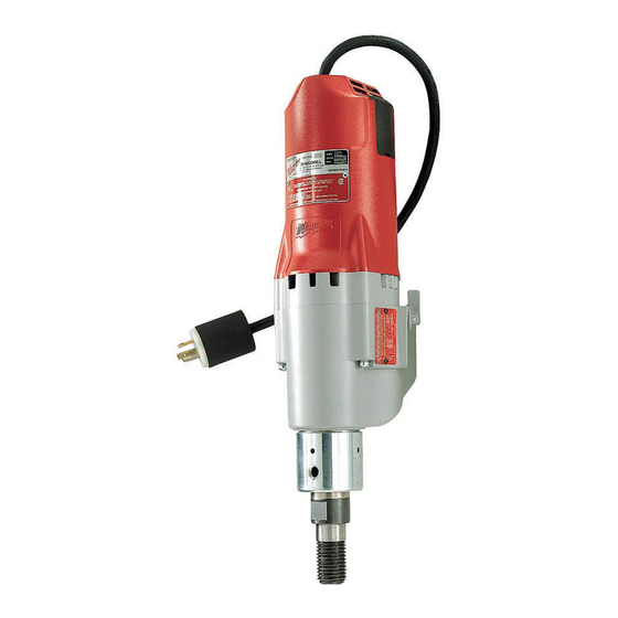
SERVICE PARTS LIST
SPECIFY CATALOG NO. AND SERIAL NO. WHEN ORDERING PARTS
DYMODRILL with INTERNAL CLUTCH
CATALOG NO.
4005-5
NO. REQ.
STARTING
865A
SERIAL NO.
FIG.
PART NO.
44
06-65-0840
45
25-60-0056
46
02-04-1229
47
16-76-0325
(1)
48
22-84-0790
(1)
49
42-14-0291
(1)
50
02-04-1041
(2)
51
06-82-9152
(3)
52
18-74-0120
(5)
53
23-16-1410
54
22-20-0680
(4)
55
22-18-0706
(2)
56
06-82-8835
(1)
57
22-56-0470
(1)
58
22-38-0140
(1)
59
31-17-0200
(1)
60
06-82-7326
(4)
61
23-37-0150
62
06-72-1720
(1)
63
12-99-1875
(1)
64
22-32-0350
(1)
65
06-82-5316
(4)
66
28-50-6363
(1)
67
06-82-5266
(1)
68
12-98-3060
(1)
69
06-95-5200
(2)
49-96-4700
(2)
49-96-0050
(1)
49-96-0085
(1)
45-56-0210
(1)
61-10-0660
(1)
(1)
FOR MOUNTING DRILL MOTOR USE:
(1)
06-75-3090
(1)
06-97-4050
(1)
FIG.
LUBRICATION
(1)
19
18 Oz. Type "J" Grease, No. 49-08-4220.
(2)
(1)
(1)
MILWAUKEE ELECTRIC TOOL CORPORATION
(1)
13135 W. LISBON RD., BROOKFIELD, WI 53005
(2)
BULLETIN NO.
55-16-5200
REVISED BULLETIN
WIRING INSTRUCTION
58-03-0020
SEE THE REVERSE SIDE
FOR THE SERVICING
OF THE INTERNAL
CLUTCH MECHANISM
DESCRIPTION OF PART
1/8 x 3/4" Groove Pin
Shifting Knob
Ball Bearing
230 V Armature
Fan
Baffle
Ball Bearing
10-24 x 2-3/4" Pan Hd. Sem. T-25
220 V. Field
Motor Insulator
Brush Tube
Carbon Brush Assembly
8-32 x 5/16" Pan Hd. Sem.T-20
Terminal Block
Wire Trap
Cord Clamp
8-16 x 1" Pan Hd. Plastite T-20
Control Assy. (See Bull. 58-03-0020)
Service Rivet
Service Nameplate
Brush Cover
8-32 x 1/2" Pan Hd. Slt. Taptite T-20
Motor Housing
4-40 x 1/4" Pan Hd. TaptiteT-10
Instruction Plate
8-32 x 5/16" Slt. Hex Hd. Screw
1-3/8" Open End Wrench
3/32" Hex Socket Wrench
3/16" Hex Socket Wrench
Strap And Buckle
Retaining Nut Spanner Tool
1/4-20 x 7/8" Socket Hd. Screw
1/4" Split Ring Lock Washer
DATE
April 2003
NO. REQ.
(1)
(1)
(1)
(1)
(1)
(1)
(1)
(2)
(1)
(1)
(2)
(2)
(2)
(1)
(1)
(1)
(2)
(1)
(2)
(1)
(2)
(2)
(1)
(2)
(1)
(1)
(1)
(1)
(1)
(1)
(1)
(4)
(4)
Drwg. 2
Advertisement

Related Manuals for Milwaukee Dymodrill


Summary of Contents for Milwaukee Dymodrill
- Page 1 SPECIFY CATALOG NO. AND SERIAL NO. WHEN ORDERING PARTS DYMODRILL with INTERNAL CLUTCH CATALOG NO. EXAMPLE: Component Parts (Small #) Are Included When Ordering The Assembly (Large #). FIG. PART NO. DESCRIPTION OF PART 42-90-0210 Water Hose Fitting 45-80-0060 Shut Off Valve...
- Page 2 25-30 ft-lbs (34-41 Nm). With the gear case separated from the diaphragm & motor housing of the Clutch Dymo-Drill motor — • insert & engage a 61-10-0660 retaining nut spanner with the notches in the 06-57-1050 clutch adjustment retaining nut.