Table of Contents
Advertisement
Visit our website at
www.MillerWelds.com
Big Blue Air Pak
OM-4409
206 941V
2007−05
Processes
Stick (SMAW) Welding
MIG (GMAW) Welding
Flux Cored (FCAW) Welding
TIG (GTAW) Welding
Air Carbon Arc (CAC-A)
Cutting and Gouging
With Optional Equipment:
Battery Charging
Description
Engine Driven Welding Generator And
Air Compressor
File: Engine Drive
Advertisement
Table of Contents

Related Manuals for Miller Electric OM-4409


Summary of Contents for Miller Electric OM-4409
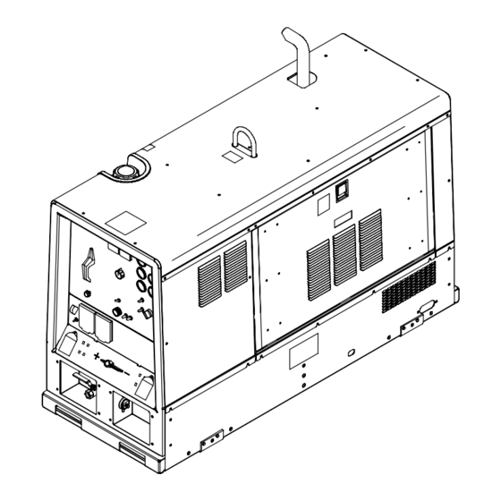
- Page 1 Big Blue Air Pak Visit our website at www.MillerWelds.com OM-4409 206 941V 2007−05 Processes Stick (SMAW) Welding MIG (GMAW) Welding Flux Cored (FCAW) Welding TIG (GTAW) Welding Air Carbon Arc (CAC-A) Cutting and Gouging With Optional Equipment: Battery Charging Description...
- Page 2 ISO 9001:2000 Quality System Standard. particular model are also provided. Miller Electric manufactures a full line of welders and welding related equipment. For information on other quality Miller products, contact your local Miller distributor to receive the latest full line catalog or individual specification sheets.
-
Page 3: Table Of Contents
TABLE OF CONTENTS SECTION 1 − SAFETY PRECAUTIONS − READ BEFORE USING 1-1. Symbol Usage ............... . 1-2. - Page 4 TABLE OF CONTENTS SECTION 7 − OPERATING AUXILIARY EQUIPMENT 7-1. 120 Volt And 240 Volt Receptacles 7-2. Connecting To Optional AC Power Plant 7-3. Optional Generator Power Receptacles SECTION 8 − OPERATING OPTIONAL BATTERY CHARGER 8-1. Battery Charge Controls ............. . . 8-2.
-
Page 5: Section 1 − Safety Precautions − Read Before Using
FLYING METAL or DIRT can injure eyes. D Welding, chipping, wire brushing, and grinding cause sparks and flying metal. As welds cool, they can throw off slag. D Wear approved safety glasses with side shields even under your welding helmet. rom_2007−04 OM-4409 Page 1... - Page 6 D Be aware that welding on a ceiling, floor, bulkhead, or partition can cause fire on the hidden side. OM-4409 Page 2 D Do not weld on closed containers such as tanks, drums, or pipes, unless they are properly prepared according to AWS F4.1 (see Safety Standards).
-
Page 7: Engine Hazards
— see applicable codes. TRAPPED AIR PRESSURE AND WHIPPING HOSES can cause injury. D Release air pressure from tools and system be- fore servicing, adding or changing attach- ments, or opening compressor oil drain or oil fill cap. OM-4409 Page 3... -
Page 8: Additional Symbols For Installation, Operation, And Maintenance
MOVING PARTS can cause injury. D Keep away from moving parts. D Keep away from pinch points such as drive rolls. OM-4409 Page 4 READ INSTRUCTIONS. D Read Owner’s Manual before using or servic- ing unit. D Stop engine and release air pressure before servicing. -
Page 9: California Proposition 65 Warnings
ARC WELDING can cause interference. D Electromagnetic energy can interfere with sensitive electronic equipment such as micro- processors, computers, and computer-driven equipment such as robots. D Be sure all equipment in the welding area is electromagnetically compatible. OM-4409 Page 5... -
Page 10: Section 2 − Consignes De Sécurité − Lire Avant Utilisation
1) un poste à souder DC semi−automatique de type CV (MIG/MAG), 2) un poste à souder manuel (électrode enrobée) DC, 3) un poste à souder OM-4409 Page 6 UTILISATION Indique des instructions spécifiques. - Page 11 NFPA 51B pour les travaux à chaud et avoir de la surveillance et un extincteur à proximité. LE BRUIT peut affecter l’ouïe. Le bruit des processus et des équipements peut affec l’ouïe. D Porter des protections approuvés pour les ore les si le niveau sonore est trop élevé. OM-4409 Page 7...
-
Page 12: Dangers Existant En Relation Avec Le Moteur
D Arrêter le moteur avant d’installer ou brancher l’appareil. OM-4409 Page 8 D Placer les bouteilles debout en les fixant dans un support station- naire ou dans un porte-bouteilles pour les empêcher de tomber ou de se renverser. -
Page 13: Dangers Liés À L'air Comprimé
D Ne lever et ne soutenir l’appareil qu’avec de l’équipement approprié et en suivant les procédures adéquates. D En utilisant des fourches de levage pour déplacer l’unité, s’assurer que les fourches sont suffisamment longues pour dépasser du côté opposé de l’appareil. pare-étincelles OM-4409 Page 9... - Page 14 D Utiliser des pochettes et des boîtes antistatiques pour stocker, déplacer ou expédier des cartes de circuits imprimes. OM-4409 Page 10 UNE REMORQUE QUI BASCULE peut entraîner des blessures. D Utiliser les supports de la remorque ou des blocs pour soutenir le poids.
-
Page 15: Proposition Californienne 65 Avertissements
Les porteurs d’implants doivent d’abord consulter leur médecin avant de s’approcher des opérations de soudage à l’arc, de soudage par points, de gougeage, du coupage plasma ou de chauffage par induc- tion. Si le médecin approuve, il est recommandé de suivre les procédures précédentes. OM-4409 Page 11... -
Page 16: Section 3 − Definitions
Check Injectors/ Pump Hourmeter (HM) Positive Amperes Output Stick (SMAW) Welding Three Phase DC Electrode Positive Circuit Protector OM-4409 Page 12 Fast (Run, Weld/ Slow (Idle) Power) Check Air Cleaner Starting Aid Jump start/Battery Battery Charge Charge Read Operator’s Certified/Trained Manual... -
Page 17: Section 4 − Specifications
103.0 Lwa sound power 104.5 Lwa sound power 78.1dBa at 23 ft (7 m) 79.6 dBa at 23 ft (7 m) 86.0 dBA 3.3 ft (1 m) 91.8 dBA 3.3 ft (1 m) from front panel from front panel OM-4409 Page 13... -
Page 18: Dimensions, Weights, And Operating Angles
No fuel: 2010 lb (907 kg) w/fuel: 2185 lb (993 kg) Lifting Eye Weight Rating 2185 lb (993 kg) Maximum Notes OM-4409 Page 14 Front Panel End Front Panel End 802 161-A Do not exceed tilt angles or engine could be damaged or unit could tip. -
Page 19: Stick And Mig Volt-Ampere Curves
The volt-ampere curve shows the minimum and maximum voltage and amperage output capabilities of the welding generator. Curves of all other settings fall between the curves shown. 1000 1000 208 135 / 203 415 / 208 956 OM-4409 Page 15... -
Page 20: Tig Volt-Ampere Curves
4-6. TIG Volt-Ampere Curves A. DC TIG Mode 50 100 150 200 250 300 350 400 450 500 550 600 650 700 B. AC TIG Mode (Optional) OM-4409 Page 16 Ranges 60−450 40−330 30−220 20−110 DC AMPERES AC AMPERES The volt-ampere curve shows the... -
Page 21: Fuel Consumption
Duty Cycle is percentage of 10 min- utes that unit can weld at rated load without overheating. NOTICE − Exceeding duty cycle can damage unit and void warranty. OM-4409 Page 17 208 211 202 356... -
Page 22: Generator Ac Power Curve
4-9. Generator AC Power Curve AC AMPERES IN 240V MODE AC AMPERES IN 120V MODE Notes OM-4409 Page 18 The ac power curve shows the gen- erator power in amperes available at the 120 and 240 volt receptacles. 193 018... -
Page 23: Optional 3-Phase Generator Power Curves
B. 20 kVA/kW Three-Phase AC Output (No Weld Load) AC AMPERES AC AMPERES The ac power curves show the gen- erator power available in amperes at the single-phase 120/240 volt re- ceptacle or three-phase 240 volt terminals. 197 472 / 197 473 OM-4409 Page 19... -
Page 24: Air Compressor Output Curve
4-11. Air Compressor Output Curve Idle CUBIC FEET PER MINUTE (CFM) 4-12. Optional Battery Charging Output Curve OM-4409 Page 20 DC AMPERES The air output curve shows the vol- ume and pressure of air available from the air compressor. The battery charging curves show the charging amperage and voltage output of the welding generator. -
Page 25: Manufacturing Rating Label
4-13. Manufacturing Rating Label OM-4409 Page 21... -
Page 26: Section 5 − Installation
18 in (460 mm) 18 in (460 mm) (460 mm) Grounding GND/PE OM-4409 Page 22 18 in (460 mm) 18 in Electrically bond generator frame to vehicle frame by metal-to-metal contact. Bed liners, shipping skids, and some running gears insulate the welding generator from the vehicle frame. -
Page 27: Mounting Welding Generator
Mount unit to truck or trailer with 1/2 in (12 mm) or larger hardware (not supplied). To Weld Unit In Place: Weld unit to truck or trailer only at the four mounting brackets. install3 8/06 803 274 / 200 864-A / 803 602 OM-4409 Page 23... -
Page 28: Installing Optional Spark Arrestor Muffler
5-3. Installing Optional Spark Arrestor Muffler Tools Needed: 7/16, 1/2 in OM-4409 Page 24 Stop engine and let cool. Spark Arrestor Muffler Double-Flanged Elbow Flat Washer Mount Bracket Screw Single-Flanged Elbow Rain Cap 10 Clamp Loosely assemble components as shown. -
Page 29: Activating The Dry Charge Battery (If Applicable)
When electrolyte is low, add only distilled water to cells to maintain proper level. drybatt1 6/05 − S-0886 Reinstall cover after connecting battery. 802 168-E / Ref. 202 705 / 802 313 / S-0756-C OM-4409 Page 25... -
Page 30: Using The Optional Battery Disconnect Switch
5-6. Using The Optional Battery Disconnect Switch Notes Start Your Professional Welding Career Now! OM-4409 Page 26 400 Trade Square East, Troy, Ohio 45373 1-800-332-9448 www.welding.org Stop engine. Battery Disconnect Switch The battery disconnect switch dis- connects battery voltage from the circuit. -
Page 31: Engine/Compressor Prestart Checks
Keep battery in good condition. Store battery in warm area. Use fuel formulated for cold weather (diesel fuel can gel in cold weather). Contact local fuel supplier for fuel in- formation. Use correct grade oil for cold weather (see Section 9-1). OM-4409 Page 27... -
Page 32: Connecting To Weld Output Terminals
Tools Needed: 3/4 in Correct Installation OM-4409 Page 28 Stick And TIG Welding For Stick welding Direct Current Electrode Positive (DCEP), connect electrode hold- er cable to Positive (+) terminal on left and work cable to Negative (−) terminal on... -
Page 33: Selecting Weld Cable Sizes
3 ea. 4/0 (3x95) (3x120) (3x120) 3 ea. 4/0 3 ea. 4/0 4 ea. 4/0 (3x120) (3x120) (4x120) OM-4409 Page 29 400 ft (120 m) 1/0 (60) 3/0 (95) 2 ea. 2/0 (2x70) 2 ea. 3/0 (2x95) 2 ea. 4/0 (2x120) 2 ea. -
Page 34: Connecting To Remote 14 Receptacle Rc14
5-10. Connecting To Remote 14 Receptacle RC14 *The remaining sockets are not used. Notes OM-4409 Page 30 Socket* 24 VOLTS AC 24 VOLTS AC REMOTE OUTPUT OUTPUT CONTROL 115 VOLTS AC 803 231 NEUTRAL Socket Information 24 volts ac. Protected by sup- plementary protector CB5. -
Page 35: Connecting To The Air Compressor
If air compressor is turned off, wait for air pressure to bleed off (about 20 seconds) before turning air compressor on again. Using the air compressor does not sig- nificantly affect weld or generator pow- er output. OM-4409 Page 31... -
Page 36: Section 6 − Operating The Welding Generator
SECTION 6 − OPERATING THE WELDING GENERATOR 6-1. Controls (See Section 6-2) 803 229 / 217 356-A OM-4409 Page 32... -
Page 37: Description Of Controls (See Section 6-1)
18 Air Shutoff Valve Air pressure is present at valve when- ever Air Pressure Gauge (item 5) indi- cates air pressure. Close valve to stop air flow when connecting or changing tools or air hoses (see Section 5-11). OM-4409 Page 33... -
Page 38: Process/Contactor Switch
Weld Terminals Always On − Air Carbon Arc (CAC-A) Cutting Stick And Gouging Weld Terminals Always On − TIG Scratch Start (GTAW) TIG, Scratch Start OM-4409 Page 34 Process/Contactor Switch Settings Process Process Output On/Off Control Output On/Off Control At Remote 14 Receptacle... -
Page 39: Using Remote Voltage/Amperage Control
Range = 40 to 330 A DC Percentage Of Range = 50% Min = 40 A DC Max (185 A DC) Min (40 A DC) Adjust Optional Remote Control 0774 / Ref. 217 356-A / 803 231 OM-4409 Page 35... -
Page 40: Section 7 − Operating Auxiliary Equipment
SECTION 7 − OPERATING AUXILIARY EQUIPMENT 7-1. 120 Volt And 240 Volt Receptacles OM-4409 Page 36 120 V 20 A AC GFCI Receptacle GFCI1 240 V 30 A AC Twistlock Receptacle RC1 Receptacles supply 60 Hz single- phase power at weld/power speed. -
Page 41: Connecting To Optional Ac Power Plant
Supplementary protector CB7 pro- tects single-phase receptacle RC5 and the load wires from overload. If CB7 opens, all ac power plant output stops and the receptacle does not work. Reinstall power panel. OM-4409 Page 37 mounting... -
Page 42: Optional Generator Power Receptacles
7-3. Optional Generator Power Receptacles European Receptacle Australian Receptacle South African Receptacle OM-4409 Page 38 120 V 20 A AC GFCI Receptacle GFCI1 240 V 16 A AC European Receptacle RC1 240 V 15 A AC Australian Receptacle RC1 240 V 15 A AC South African... -
Page 43: Section 8 − Operating Optional Battery Charger
EXAMPLE: If battery CCA rating is 500, charging current from chart is 100 amperes. Do not exceed charging current found on chart. For longer battery life, use lowest charge rate possible. 142 975-B OM-4409 Page 39... -
Page 44: Battery Charge Cable Connections
Keep cables away from moving parts. Do not use damaged cables. Be sure charger output voltage matches battery voltage. OM-4409 Page 40 − Read BCI Battery Service Manual before charging or jump starting. Before connecting to battery, place Output Selector switch in position matching voltage of battery being charged. -
Page 45: Battery Charging Procedure
Set Output Selector Switch To Voltage Of Battery Being Charged (12 Or 24 Volt). NOTICE − Do not switch under load. − Connect Cables (Observe Correct Polarity). Charge 10 minutes. Check Battery Voltage. Continue Charging If Necessary. OM-4409 Page 41... -
Page 46: Jump Starting Procedure
8-5. Jump Starting Procedure Stop Engine. Set Ampere Range Switch To 300-Max Position. NOTICE − Do not switch under load. Start Engine. OM-4409 Page 42 Set Process/Contactor Switch To Any Remote On/Off Switch Required Position. − Connect Cables (Observe Correct Polarity). -
Page 47: Section 9 − Engine/Generator Maintenance
SECTION 9 − ENGINE/GENERATOR MAINTENANCE 9-1. Engine Maintenance Label OM-4409 Page 43... -
Page 48: Routine Engine/Generator Maintenance
3000 Hours ~ Injectors* Every 6000 Hours or 5 Years nl Engine Timing Belt OM-4409 Page 44 Recycle engine fluids. ~ = Clean l = Replace n Oil Level n Air Cleaner Element 1/2 in. (13 mm) ~ Cooling System... -
Page 49: Checking Generator Brushes
20 Gauge (.037 in) 18 Gauge (.050 in) 16 Gauge (.063 in) 14 Gauge (.078 in) 1/8 in (.125 in) 3/16 in (.188 in) 1/4 in (.25 in) 5/16 in (.313 in) 3/8 in (.375 in) 1/2 in (.5 in) OM-4409 Page 45... -
Page 50: Servicing Engine Air Cleaner
Optional Keep nozzle 2 in (51 mm) from element. Blow OM-4409 Page 46 Inspect aircleaner1 9/00 − 803 228 / 153 929-B / 153 585 / Ref. S-0698-B Stop engine. NOTICE − Do not run engine without air cleaner or with dirty element. Engine damage caused by using a damaged ele- ment is not covered by the warranty. -
Page 51: Inspecting/Cleaning Optional Spark Arrestor Muffler
Start engine and run at idle speed to blow out cleanout hole. If nothing blows out of hole, briefly cover end of exhaust pipe with fireproof material. Stop engine and let cool. Reinstall cleanout plug. 803 228 / 803 230 OM-4409 Page 47... -
Page 52: Adjusting Engine Speed
9-6. Adjusting Engine Speed Tools Needed: 3/8, 7/16 in OM-4409 Page 48 Stop engine and let cool. Engine speed is factory set and should not require adjustment. Af- ter tuning engine, check engine no load speed with a tachometer or fre- quency meter (see table for no load speeds). -
Page 53: Servicing Engine Fuel And Lubrication Systems
Attach 1/2 ID hose to drain valve. Put metal container under drain, and use screwdriver to open sludge drain valve. Close valve when sludge has drained. Remove hose. OM-4409 Page 49... -
Page 54: Engine/Generator Overload Protection
9-8. Engine/Generator Overload Protection OM-4409 Page 50 Stop engine. When a supplementary protector, circuit breaker or fuse opens, it usually indicates a more serious problem exists. Contact Factory Authorized Service Agent. See Section 10-4 for air compres- sor overload protection. -
Page 55: Section 10 − Air Compressor Maintenance
The air compressor normally requires service at the intervals listed in the maintenance schedule if used in a clean, dry environment. The compres- sor will require service more often if used in dirty, humid conditions. 10-1. Air Compressor Maintenance Label OM-4409 Page 51... -
Page 56: Routine Air Compressor Maintenance
Hours Z Oil Z Oil Filter Every 1000 Hours Z Air/Oil Separator OM-4409 Page 52 Stop engine before maintaining. See Compressor Maintenance Label for im- Recycle air portant start-up, service, and storage infor- compressor mation. Service air compressor more often fluids. -
Page 57: Servicing Compressor Air Cleaner
(690 kPa). Use 1/8 in (3 mm) nozzle and keep nozzle at least 2 in (51 mm) from inside of element. Replace primary ele- ment if it has holes or damaged gaskets. Reinstall primary element and cover (dust ejector down). OM-4409 Page 53... -
Page 58: Compressor Overload Protection
10-4. Compressor Overload Protection OM-4409 Page 54 Stop engine. When a circuit breaker or fuse opens, it usually indicates a more serious problem exists. Contact Factory Authorized Service Agent. See Section 9-8 for engine/genera- tor overload protection. Circuit Breaker CB15 Circuit breaker CB15 protects the air compressor clutch. -
Page 59: Servicing Air Compressor
Lift oil scavenge tube from separator. Turn fil- ter counterclockwise. Remove filter. Apply thin coat of oil to gasket on new filter. Install filter and turn clockwise. Reinstall oil scavenge tube. Start engine, run air compressor, and check for oil leaks. Stop engine. OM-4409 Page 55... -
Page 60: Adjusting Compressor Air Pressure
10-6. Adjusting Compressor Air Pressure Tools Needed: 5/16, 3/8 in OM-4409 Page 56 Check compressor air pressure using air pressure gauge known to be accu- rate. If necessary, adjust air pressure as follows: Screw Loosen jam nut securing screw. Turn... -
Page 61: Section 11 − Troubleshooting
Check engine weld/power speed, and adjust if necessary. No remote fine amperage or voltage Place Panel/Remote Switch in Remote position. control. Check and secure connections to Remote 14 receptacle RC14 (see Section 5-10). Repair or replace remote control device. Remedy OM-4409 Page 57... - Page 62 Have Factory Authorized Service Agent check field current regulator board PC1. Erratic output at optional ac power plant/ Have Factory Authorized Service Agent check brushes and slip rings, and field current regulator board receptacle RC5. PC1. OM-4409 Page 58 Remedy Remedy Remedy...
- Page 63 Recharge or replace battery if necessary. Periodically recharge battery (approximately every 3 months). Engine idles, but does not come up to Have Factory Authorized Service Agent check idle module PC7. weld speed. Check for obstructed throttle solenoid. Remedy OM-4409 Page 59...
- Page 64 SR1, capacitor C9, field current regulator board PC1, and the rotor. Reset supplementary protector CB12 (see Section 9-8). Have Factory Authorized Service Agent check brushes and slip rings, field current regulator board PC1, and field excitation circuit. OM-4409 Page 60 Remedy Remedy Remedy...
-
Page 65: Section 12 − Air Compressor Diagram
SECTION 12 − AIR COMPRESSOR DIAGRAM 209 059-A Figure 12-1. Circuit Diagram For Air Compressor OM-4409 Page 61... -
Page 66: Section 13 − Circuit Diagram
SECTION 13 − CIRCUIT DIAGRAM Figure 13-1. Circuit Diagram For Welding Generator OM-4409 Page 62... - Page 67 221 915−C OM-4409 Page 63...
-
Page 68: Section 14 − Run-In Procedure
SECTION 14 − RUN-IN PROCEDURE 14-1. Wetstacking OM-4409 Page 64 run_in1 2007−04 NOTICE − Do not perform run-in procedure at less than 20 volts weld output and do not exceed duty cycle or equipment damage may occur. Welding Generator Run diesel engines near rated volt-... -
Page 69: Run-In Procedure Using Load Bank
Place A/V control in minimum position, then turn off load bank to remove load. Run engine several minutes at no load. Stop engine and let cool. Engine Exhaust Pipe Repeat procedure if wetstacking is present. S-0683 OM-4409 Page 65... -
Page 70: Run-In Procedure Using Resistance Grid
14-3. Run-In Procedure Using Resistance Grid OM-4409 Page 66 Stop engine. Do not touch hot exhaust pipe, engine parts, or load bank/grid. Keep exhaust and pipe away from flammables. NOTICE − Do not perform run-in procedure at less than 20 volts weld... -
Page 71: Section 15 − Air Compressor Tables
16.8 37.5 67.0 19.0 43.0 76.0 11.9 21.2 47.5 85.0 23.5 52.5 94.0 25.8 58.3 103.0 28.0 63.0 112.0 30.2 68.0 121.0 32.4 73.0 130.0 34.5 78.0 138.0 36.7 83.0 147.0 42.1 95.0 169.0 48.7 110.0 195.0 OM-4409 Page 67... -
Page 72: Approximate Air Consumption (Cubic Feet) To Operate Pneumatic Equipment At 70-90 P.s.i.g
Above tools are rated based upon typical “on-load” performance characteristics. For other values, adjust the C.F. air consumption on a proportional basis. The cubic feet (C.F.) air consumption for 1 minute may also be expressed as air consumption in cubic feet per minute (C.F.M.) OM-4409 Page 68 MISCELLANEOUS PORTABLE... -
Page 73: Section 16 − Generator Power Guidelines
Al- ways connect a ground wire from the generator equip- ment grounding terminal to bare metal on the vehicle frame as shown. If unit does not have GFCI re- ceptacles, use GFCI-pro- tected extension cord. S-0854 OM-4409 Page 69... -
Page 74: Grounding When Supplying Building Systems
16-3. Grounding When Supplying Building Systems 16-4. How Much Power Does Equipment Require? OM-4409 Page 70 GND/PE VOLTS 115 AMPS Equipment Grounding Terminal Grounding Cable Use #10 AWG or larger insulated copper wire. Ground Device Use ground device as stated in electrical codes. - Page 75 1/2 HP 3200 Running Watts 1400 1600 2200 2850 3900 6800 2000 6000 8000 10700 1100 Running Watts 1000 1000 1400 1100 2800 1400 1600 2200 2850 3900 6800 2000 6000 8000 10700 1000 1400 1600 1000 1050 OM-4409 Page 71...
- Page 76 Elec. Hedge Trimmer Flood Lights Submersible Pump Centrifugal Pump Floor Polisher High Pressure Washer 55 gal Drum Mixer Wet & Dry Vac OM-4409 Page 72 Rating Starting Watts 1/4 in 3/8 in 1/2 in 6-1/2 in 7-1/4 in 8-1/4 in...
- Page 77 5 Second Rule If motor does not start within 5 seconds, turn off power to prevent motor damage. Motor requires more power than generator can supply. Ref. ST-800 396-A / S-0625 OM-4409 Page 73 14.0 S-0624...
- Page 78 16-10. Typical Connections To Supply Standby Power Utility Electrical Transfer Switch Service Essential Loads OM-4409 Page 74 Fused Welding Disconnect Generator Switch Output (If Required) Have only qualified persons perform these connections according to all applicable codes and safety practices.
- Page 79 30 (9) 37 (11) 37 (11) 450 (137) 225 (84) 200 (61) 300 (91) 200 (61) 125 (38) 225 (69) 125 (38) 100 (31) 150 (46) 75 (23) 60 (18) 100 (31) 60 (18) 75 (23) 75 (23) OM-4409 Page 75...
-
Page 80: Section 17 − Selecting And Preparing A Tungsten For Dc Or Ac Welding
A. Preparing Tungsten For DC Electrode Negative (DCEN) Welding Radial Grinding Causes Wandering Arc Wrong Tungsten Preparation B. Preparing Tungsten For AC Welding OM-4409 Page 76 Wear Clean gloves To Prevent Contamination Of Tungsten Amperage Range - Gas Type (DCEN) − Argon Direct Current Electrode Negative... -
Page 81: Section 18 − Guidelines For Tig Welding (Gtaw)
The tungsten extension should be no greater than the inside diameter of the gas cup. Arc length is the distance from the tungsten to the workpiece. Ref. ST-161 892 OM-4409 Page 77... -
Page 82: Torch Movement During Welding
Form pool Tilt torch Move torch to front of pool. Repeat process. Tungsten With Filler Rod Welding direction Form pool Tilt torch Add filler metal Remove rod Move torch to front of pool. Repeat process. ST-162 002-B OM-4409 Page 78... -
Page 83: Positioning Torch Tungsten For Various Weld Joints
18-3. Positioning Torch Tungsten For Various Weld Joints Butt Weld And Stringer Bead “T” Joint Lap Joint Corner Joint ST-162 003 / S-0792 OM-4409 Page 79... -
Page 84: Section 19 − Parts List
SECTION 19 − PARTS LIST Hardware is common and not available unless listed. 144 − Figure 19-3 OM-4409 Page 80 11 12 146 − Figure 19-5 131 − Figure 19-2 Figure 19-1. Main Assembly... - Page 85 112 − Figure 19-4 62 63 99 100 803 324 OM-4409 Page 81...
- Page 86 205712 ....205748 OM-4409 Page 82 Description Figure 19-1. Main Assembly Panel, Gen LH ..........
- Page 87 ............OM-4409 Page 83 Quantity...
- Page 88 ... . . 206463 ... . . 233953 OM-4409 Page 84 Description Figure 19-1. Main Assembly (Continued) Hose Assy, Oil Drain 32.000 Lg (includes) Valve, Oil Drain 3/8−18 Nptf...
- Page 89 ..........OM-4409 Page 85 Quantity...
- Page 90 087110 ....177136 OM-4409 Page 86 Figure 19-2. Control Box Assembly Description Fuse, Mintr Cer Slo−blo 10. Amp 250 Volt Holder, Fuse Mintr .250 X 1.250 Panel Mtg Stand−off Support, Pc Card .312/.375w/Post&lock .43...
- Page 91 ..........OM-4409 Page 87 Quantity...
- Page 92 148389 ... . . 193118 OM-4409 Page 88 Figure 19-3. Panel, Front w/Components Description Plate, Screened Ident Control Rating Panel, Engine/Weld Control ........
- Page 93 ..........OM-4409 Page 89 Quantity...
- Page 94 When ordering a component originally displaying a precautionary label, the label should also be ordered. To maintain the factory original performance of your equipment, use only Manufacturer’s Suggested Replacement Parts. Model and serial number required when ordering parts from your local distributor. OM-4409 Page 90 Description Switch, Handle (Polarity/AC Switch) Pin (Polarity/AC Switch) .
- Page 95 ..........OM-4409 Page 91 803 327...
- Page 96 Optional To maintain the factory original performance of your equipment, use only Manufacturer’s Suggested Replacement Parts. Model and serial number required when ordering parts from your local distributor. OM-4409 Page 92 Description Figure 19-4. Generator (Continued) Screw, M10−1.5x 50 Hex Hd−pln 8.8 Pld Screw, 312−18x .75 Hexwhd.66d Stl Pld Slffmg Tap−rw...
- Page 97 ..........OM-4409 Page 93 802 279-A...
- Page 98 Hardware is common and not available unless listed. OM-4409 Page 94 Figure 19-6. Air Compressor Assembly 803 328−G...
- Page 99 ............OM-4409 Page 95 Quantity...
- Page 100 218423 To maintain the factory original performance of your equipment, use only Manufacturer’s Suggested Replacement Parts. Model and serial number required when ordering parts from your local distributor. OM-4409 Page 96 Description Figure 19-5. Air Compressor Assembly (Continued) Plate, Mtg Compressor To Bracket Valve, Inlet Unloader 90dg .
- Page 101 Warranty Questions? LIMITED WARRANTY − Subject to the terms and conditions Call below, Miller Electric Mfg. Co., Appleton, Wisconsin, warrants to 1-800-4-A-MILLER its original retail purchaser that new Miller equipment sold after the effective date of this limited warranty is free of defects in for your local material and workmanship at the time it is shipped by Miller.
- Page 102 File a claim for loss or damage during shipment. For assistance in filing or settling claims, contact your distributor and/or equipment manufacturer’s Transportation Department. 2007 Miller Electric Mfg. Co. 2007−01 Miller Electric Mfg. Co. An Illinois Tool Works Company 1635 West Spencer Street Appleton, WI 54914 USA International Headquarters−USA...