Table of Contents
Troubleshooting

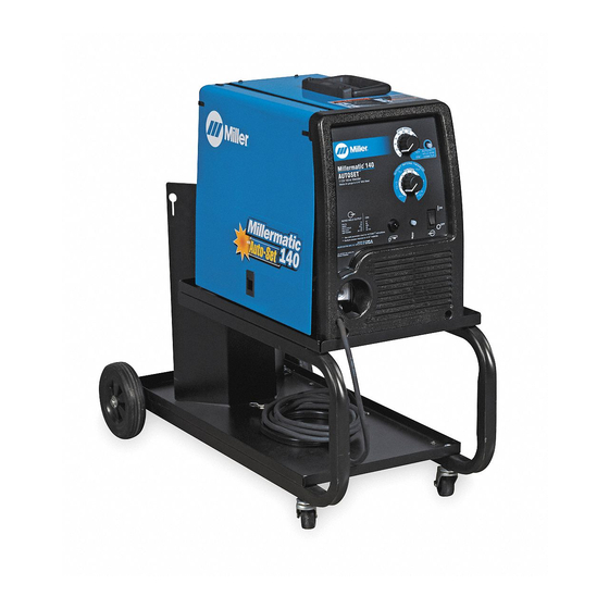
Related Manuals for Miller Electric Millermatic 140 Auto−Set


Summary of Contents for Miller Electric Millermatic 140 Auto−Set
- Page 1 140 Auto−Set , And 180 Visit our website at www.MillerWelds.com Millermatic 140, And M-10 Gun OM-225 311C 2007−05 Processes MIG (GMAW) Welding Flux Cored (FCAW) Welding Description Arc Welding Power Source And Wire Feeder File: MIG (GMAW)
- Page 2 ISO 9001:2000 Quality System Standard. particular model are also provided. Miller Electric manufactures a full line of welders and welding related equipment. For information on other quality Miller products, contact your local Miller distributor to receive the latest full line catalog or individual specification sheets.
-
Page 3: Table Of Contents
TABLE OF CONTENTS SECTION 1 − SAFETY PRECAUTIONS - READ BEFORE USING 1-1. Symbol Usage ............... . 1-2. - Page 4 TABLE OF CONTENTS SECTION 6 − MAINTENANCE &TROUBLESHOOTING 6-1. Routine Maintenance ..............6-2.
-
Page 5: Section 1 − Safety Precautions - Read Before Using
SECTION 1 − SAFETY PRECAUTIONS - READ BEFORE USING Y Warning: Protect yourself and others from injury — read and follow these precautions. 1-1. Symbol Usage Means Warning! Watch Out! There are possible hazards with this procedure! The possible hazards are shown in the adjoining symbols. - Page 6 ARC RAYS can burn eyes and skin. Arc rays from the welding process produce intense visible and invisible (ultraviolet and infrared) rays that can burn eyes and skin. Sparks fly off from the weld. D Wear an approved welding helmet fitted with a proper shade of fil- ter lenses to protect your face and eyes when welding or watching (see ANSI Z49.1 and Z87.1 listed in Safety Standards).
-
Page 7: Additional Symbols For Installation, Operation, And Maintenance
1-3. Additional Symbols For Installation, Operation, And Maintenance FIRE OR EXPLOSION hazard. D Do not install or place unit on, over, or near combustible surfaces. D Do not install unit near flammables. D Do not overload building wiring − be sure power supply system is properly sized, rated, and protected to handle this unit. -
Page 8: Principal Safety Standards
1-5. Principal Safety Standards Safety in Welding, Cutting, and Allied Processes, ANSI Standard Z49.1, from Global Engineering Documents (phone: 1-877-413-5184, website: www.global.ihs.com). Recommended Safe Practices for the Preparation for Welding and Cut- ting of Containers and Piping, American Welding Society Standard F4.1 from Global... -
Page 9: Section 2 − Consignes De Sécurité − Lire Avant Utilisation
SECTION 2 − CONSIGNES DE SÉCURITÉ − LIRE AVANT UTILISATION Y Avertissement : se protéger et protéger les autres contre le risque de blessure — lire et respecter ces consignes. 2-1. Symboles utilisés Symbole graphique d’avertissement ! Attention ! Cette pro- cédure comporte des risques possibles ! Les dangers éven- tuels sont représentés par les symboles graphiques joints. - Page 10 LES RAYONS D’ARC peuvent entraî- ner des brûlures aux yeux et à la peau. Le rayonnement de l’arc du procédé de soudage génère des rayons visibles et invisibles intenses (ultraviolets et infrarouges) susceptibles de provo- quer des brûlures dans les yeux et sur la peau. Des étincelles sont projetées pendant le soudage.
-
Page 11: Dangers Supplémentaires En Relation Avec L'installation, Le Fonctionnement Et La Maintenance
2-3. Dangers supplémentaires en relation avec l’installation, le fonctionnement et la maintenance Risque D’INCENDIE OU D’EXPLO- SION. D Ne pas placer l’appareil sur, au-dessus ou à proximité de surfaces inflammables. D Ne pas installer l’appareil à proximité de produits inflammables. D Ne pas surcharger l’installation électrique −... -
Page 12: Principales Normes De Sécurité
2-5. Principales normes de sécurité Safety in Welding, Cutting, and Allied Processes, ANSI Standard Z49.1, de Global Engineering Documents (téléphone : 1-877-413-5184, site In- ternet : www.global.ihs.com). Recommended Safe Practices for the Preparation for Welding and Cut- ting of Containers and Piping, American Welding Society Standard AWS F4.1 de Global Engineering Documents (téléphone : 1-877-413-5184, site Internet : www.global.ihs.com). -
Page 13: Section 3 − Specifications
A complete Parts List is available on-line at www.MillerWelds.com SECTION 3 − SPECIFICATIONS 3-1. Specifications A. 115 VAC Model Rated Welding Amperage Range Output 90 A @ 18 Volts DC, 20% Duty Cycle 30 − 140 63 A @ 21 Volts DC, 20% Duty Cycle* Solid... -
Page 14: Duty Cycle And Overheating
A complete Parts List is available on-line at www.MillerWelds.com 3-2. Duty Cycle And Overheating A. 115 VAC Model 2 Minutes Welding B. 230 VAC Model 3 Minutes Welding Overheating OM-225 311 Page 10 20% duty cycle at 90 amps 8 Minutes Resting 30% duty cycle at 135 amps, 60 Hz 7 Minutes Resting Reduce Duty Cycle... -
Page 15: Volt-Ampere Curves
A complete Parts List is available on-line at www.MillerWelds.com 3-3. Volt-Ampere Curves A. 115 VAC Model A M PE R A G E B. 230 VAC Model A M PER A G E The volt-ampere curves show the minimum and maximum voltage and amperage output capabilities of the welding power source. -
Page 16: Section 4 − Installation
A complete Parts List is available on-line at www.MillerWelds.com SECTION 4 − INSTALLATION 4-1. Installing Welding Gun Be sure that gun end is tight against drive assembly. Correct 4-2. Installing Work Clamp Connection hardware must be tightened with proper tools. Do not just hand tighten hardware. -
Page 17: Work Cable Routing Inside Unit
A complete Parts List is available on-line at www.MillerWelds.com 4-3. Work Cable Routing Inside Unit 4-4. Process/Polarity Table Process Process GMAW − Solid wire with shield- DCEP − Reverse polarity ing gas FCAW − Self-shielding wire − DCEN − Straight Polarity no shielding gas 4-5. -
Page 18: Installing Gas Supply
A complete Parts List is available on-line at www.MillerWelds.com 4-6. Installing Gas Supply DO NOT use Argon/Mixed gas regulator/flowmeter with CO shielding gas. See Parts List for optional gas regulator/flowmeter and hose. Tools Needed: 5/8, 1-1/8 in OM-225 311 Page 14 Obtain gas cylinder and chain to running gear, stationary support so cylinder... -
Page 19: Selecting A Location And Connecting Input Power For 115 Vac Model
A complete Parts List is available on-line at www.MillerWelds.com 4-7. Selecting A Location And Connecting Input Power For 115 VAC Model 18 in (460 mm) 18 in (460 mm) Rating Label Grounded Receptacle A 115 volt, 20 ampere individual branch circuit protected by time-delay fuses or circuit breaker is required. -
Page 20: Selecting A Location And Connecting Input Power For 230 Vac Model
A complete Parts List is available on-line at www.MillerWelds.com 4-8. Selecting A Location And Connecting Input Power For 230 VAC Model Y Do not move or operate unit where it could tip. 18 in (457 mm) of space for airflow Tools Needed: OM-225 311 Page 16 =GND/PE Earth... -
Page 21: Electrical Service Guide For 230 Vac Model
A complete Parts List is available on-line at www.MillerWelds.com 4-9. Electrical Service Guide For 230 VAC Model Input Voltage Input Amperes At Rated Output Max Recommended Standard Fuse Rating In Amperes Min Input Conductor Size In AWG Max Recommended Input Conductor Length In Feet (Meters) Min Grounding Conductor Size In AWG Reference: 2005 National Electrical Code (NEC) (including article 630) 1 Choose a circuit breaker with time-current curves comparable to a Time Delay Fuse. -
Page 22: Threading Welding Wire
A complete Parts List is available on-line at www.MillerWelds.com 4-11. Threading Welding Wire Tools Needed: Open pressure assembly. Tighten Be sure that wire is positioned in proper drive roll groove and wire is laying in the groove. Close and tighten pressure assembly, and let go of wire. -
Page 23: Removing Mig Gun From Welding Power Source
A complete Parts List is available on-line at www.MillerWelds.com 4-12. Removing MIG Gun From Welding Power Source Open Pressure Assembly Cut Off End Of Wire Knob Hold wire tightly to keep it from unraveling. Loosen Knob, Disconnect Gun Trigger Rewind Wire Onto Spool, Fasten Plug, And Pull Gun From Unit End Of Wire To Spool Ref. -
Page 24: Installing Optional Spool Gun Switch In Welding Power Source
A complete Parts List is available on-line at www.MillerWelds.com 4-13. Installing Optional Spool Gun Switch In Welding Power Source Tools Needed: 1/4, 5/16 in OM-225 311 Page 20 9/16 in Y Turn Off unit, and disconnect input power. For units prior to Serial No. LH210051N, use retrokit part no. -
Page 25: Connecting Spool Gun To Millermatic 140/180
A complete Parts List is available on-line at www.MillerWelds.com 4-14. Connecting Spool Gun To Millermatic 140/180 Be sure that gun end is tight against drive assembly. Incorrect Exposed O-rings will cause shielding Gun Not Seated Correct Gun Fully Seated gas leakage. Drive Assembly Spool Gun Gun Securing Knob... -
Page 26: Section 5 − Operation
A complete Parts List is available on-line at www.MillerWelds.com SECTION 5 − OPERATION 5-1. Controls For 115 VAC Model w/Auto-SetE Wire Speed Control Turn control clockwise inside white scale (10-100) to increase wire feed speed. (see weld parameter chart in welding power source or Section 5-4, 5-5, 5-6, 5-7, or 5-8 as applicable). -
Page 27: Controls For 115 Vac Model
A complete Parts List is available on-line at www.MillerWelds.com 5-2. Controls For 115 VAC Model 115V Wire Welder Welds 24 gauge to 3/16" Mild Steel Wire Speed Control Turn control clockwise to increase wire feed speed. (see weld parameter chart in welding power source or Section 5-4, 5-5, 5-6, 5-7, or 5-8, as applicable). -
Page 28: Controls For 230 Vac Model
A complete Parts List is available on-line at www.MillerWelds.com 5-3. Controls For 230 VAC Model 230V Wire Welder Welds 24 gauge to 5/16" Mild Steel Wire Speed Control Turn control clockwise to increase wire feed speed. (see weld parameter chart in welding power source or Section 5-5, 5-4, 5-6, 5-7 or 5-8, as applicable). - Page 29 A complete Parts List is available on-line at www.MillerWelds.com Notes OM-225 311 Page 25...
-
Page 30: Weld Parameter Chart For 115 Vac Model W/Auto−Sett
A complete Parts List is available on-line at www.MillerWelds.com 5-4. Weld Parameter Chart For 115 VAC Model w/Auto−SetE Auto−Sett − SIMPLE SETUP FOR WELDING MILD STEEL Example: .030” diameter wire, welding 18 ga. material. .024” Auto−Set* WELD WIRE .030” DIAMETER M A T ERI A L T H o −... - Page 31 A complete Parts List is available on-line at www.MillerWelds.com Manual Setup Refer to chart below to select Voltage and Wire Speed based on thickness of metal being welded. M A TER I A L T H I o − 2/40 3/50 3/50 4/65...
-
Page 32: Weld Parameter Chart For 115 Vac Model W/Factory Set
A complete Parts List is available on-line at www.MillerWelds.com 5-5. Weld Parameter Chart For 115 VAC Model w/Factory Set Non-Wire Speed Tracking Mode Refer to chart below to select Voltage and Wire Speed based on thickness of material being welded. 1. - Page 33 A complete Parts List is available on-line at www.MillerWelds.com NOTE: Settings are approximate. Adjust as required. “−−−” Means not recommended. “*” Thicker materials can be welded using proper technique, joint preparation and multiple passes. IMPORTANT: Match drive roll groove to diameter of wire being used. Set Tension knob setting to 3 at start.
-
Page 34: Weld Parameter Chart For 115 Vac Model W/Wire Speed Tracking Mode
A complete Parts List is available on-line at www.MillerWelds.com 5-6. Weld Parameter Chart For 115 VAC Model w/Wire Speed Tracking Mode Refer to chart below to select Voltage and Wire Speed based on thickness of material being welded. 1. Number on left of slash is Voltage Knob Setting. - Page 35 A complete Parts List is available on-line at www.MillerWelds.com NOTE: Settings are approximate. Adjust as required. “−−−” Means not recommended. “*” Thicker materials can be welded using proper technique, joint preparation and multiple passes. IMPORTANT: Match drive roll groove to diameter of wire being used. Set Tension knob setting to 3 at start.
-
Page 36: Weld Parameter Chart For 230 Vac Model W/Factory Set
A complete Parts List is available on-line at www.MillerWelds.com 5-7. Weld Parameter Chart For 230 VAC Model w/Factory Set Non-Wire Speed Tracking Mode Refer to chart below to select Voltage and Wire Speed based on thickness of material being welded. 1. - Page 37 A complete Parts List is available on-line at www.MillerWelds.com NOTE: Settings are approximate. Adjust as required. “−−−” Means not recommended. Thicker materials can be welded using proper technique, joint preparation and multiple passes. IMPORTANT: Match drive roll groove to diameter of wire being used. Set Tension knob setting to 3 at start.
-
Page 38: Weld Parameter Chart For 230 Vac Model W/Wire Speed Tracking Mode
A complete Parts List is available on-line at www.MillerWelds.com 5-8. Weld Parameter Chart For 230 VAC Model w/Wire Speed Tracking Mode Refer to chart below to select Voltage and Wire Speed based on thickness of material being welded. 1. Number on left of slash is Voltage Knob Setting. - Page 39 A complete Parts List is available on-line at www.MillerWelds.com NOTE: Settings are approximate. Adjust as required. “−−−” Means not recommended. “*” Thicker materials can be welded using proper technique, joint preparation and multiple passes. IMPORTANT: Match drive roll groove to diameter of wire being used. Set Tension knob setting to 3 at start.
-
Page 40: Section 6 − Maintenance &Troubleshooting
A complete Parts List is available on-line at www.MillerWelds.com SECTION 6 − MAINTENANCE &TROUBLESHOOTING 6-1. Routine Maintenance n = Check Z = Change * To be done by Factory Authorized Service Agent Every Months l Unreadable Labels ~ Weld Terminals Every Months ~ Inside Unit... -
Page 41: Changing Drive Roll Or Wire Inlet Guide
A complete Parts List is available on-line at www.MillerWelds.com 6-4. Changing Drive Roll Or Wire Inlet Guide .030/.035 Groove .024 Groove Stamped .024 Stamped .030/.035 6-5. Replacing Gun Contact Tip Tools Needed: Inlet Wire Guide Remove guide by pressing on barbed area or cutting off one end near housing and pulling it out of hole. -
Page 42: Cleaning Or Replacing Gun Liner
A complete Parts List is available on-line at www.MillerWelds.com 6-6. Cleaning Or Replacing Gun Liner 8 mm Lay gun cable out straight before installing new liner. OM-225 311 Page 38 Y Disconnect gun from unit. Head Tube Remove nozzle, contact tip, adapter, gas diffuser, and wire outlet guide. -
Page 43: Replacing Switch And/Or Head Tube
A complete Parts List is available on-line at www.MillerWelds.com 6-7. Replacing Switch And/Or Head Tube Remove handle locking nut. Secure head tube in vice. Loosen jam nut. Remove from vice and turn head tube out by hand. Hand-tighten head tube into cable connector. Tools Needed: 19 mm Y Turn Off welding power source... -
Page 44: Troubleshooting Table
A complete Parts List is available on-line at www.MillerWelds.com 6-8. Troubleshooting Table Trouble No weld output; wire does not feed; fan Secure power cord plug in receptacle (see Section 4-7 or 4-8). does not run. does not run. Replace building line fuse or reset circuit breaker if open. Place Power switch in On position (see Section 5-2, 5-1, or 5-3). - Page 45 Notes OM-225 311 Page 41...
-
Page 46: Section 7 − Electrical Diagram
SECTION 7 − ELECTRICAL DIAGRAM Figure 7-1. Circuit Diagram OM-225 311 Page 42... - Page 47 234 419-B OM-225 311 Page 43...
-
Page 48: Section 8 − Mig Welding (Gmaw) Guidelines
SECTION 8 − MIG WELDING (GMAW) GUIDELINES 8-1. Typical MIG Process Connections Regulator/ Flowmeter Gas Hose Shielding Gas OM-225 311 Page 44 Wire Feeder/ Power Source Y Weld current can damage electronic parts in vehicles. Disconnect both battery cables before welding on a vehicle. -
Page 49: Typical Mig Process Control Settings
8-2. Typical MIG Process Control Settings NOTE These settings are guidelines only. Material and wire type, joint design, fitup, position, shielding gas, etc. affect settings. Test welds to be sure they comply to specifications. Material thickness determines weld parameters. .035 in Wire Recommendation Size... -
Page 50: Holding And Positioning Welding Gun
8-3. Holding And Positioning Welding Gun NOTE Welding wire is energized when gun trigger is pressed. Before lowering helmet and pressing trigger, be sure wire is no more than 1/2 in (13 mm) past end of nozzle, and tip of wire is positioned correctly on seam. End View Of Work Angle End View Of Work Angle OM-225 311 Page 46... -
Page 51: Conditions That Affect Weld Bead Shape
8-4. Conditions That Affect Weld Bead Shape NOTE Weld bead shape depends on gun angle, direction of travel, electrode extension (stickout), travel speed, thickness of base metal, wire feed speed (weld current), and voltage. Short Short FILLET WELD ELECTRODE EXTENSIONS (STICKOUT) Slow Push Perpendicular... -
Page 52: Gun Movement During Welding
8-5. Gun Movement During Welding NOTE Normally, a single stringer bead is satisfactory for most narrow groove weld joints; however, for wide groove weld joints or bridging across gaps, a weave bead or multiple stringer beads works better. 8-6. Poor Weld Bead Characteristics 8-7. -
Page 53: Troubleshooting − Excessive Spatter
8-8. Troubleshooting − Excessive Spatter Possible Causes Wire feed speed too high. Voltage too high. Electrode extension (stickout) too long. Workpiece dirty. Insufficient shielding gas at welding arc. Dirty welding wire. Wrong polarity. 8-9. Troubleshooting − Porosity Possible Causes Insufficient shielding gas at welding arc. Wrong gas. -
Page 54: Troubleshooting − Excessive Penetration
8-10. Troubleshooting − Excessive Penetration Excessive Penetration Good Penetration Possible Causes Excessive heat input. Wrong polarity. 8-11. Troubleshooting − Lack Of Penetration Lack of Penetration Good Penetration Possible Causes Improper joint preparation. Improper weld technique. Insufficient heat input. Wrong polarity. 8-12. -
Page 55: Troubleshooting − Burn-Through
8-13. Troubleshooting − Burn-Through Possible Causes Excessive heat input. Wrong polarity. 8-14. Troubleshooting − Waviness Of Bead Possible Causes Welding wire extends too far out of nozzle. Unsteady hand. 8-15. Troubleshooting − Distortion Base metal moves in the direction of the weld bead. -
Page 56: Common Mig Shielding Gases
8-16. Common MIG Shielding Gases This is a general chart for common gases and where they are used. Many different combinations (mixtures) of shielding gases have been developed over the years. The most commonly used shielding gases are listed in the following table. -
Page 57: Section 9 − Parts List
SECTION 9 − PARTS LIST 9-1. Recommended Spare Parts Item Part ..... 169 715 ....087 299 . - Page 58 Notes...
- Page 59 Warranty Questions? LIMITED WARRANTY − Subject to the terms and conditions Call below, Miller Electric Mfg. Co., Appleton, Wisconsin, warrants to 1-800-4-A-MILLER its original retail purchaser that new Miller equipment sold after the effective date of this limited warranty is free of defects in for your local material and workmanship at the time it is shipped by Miller.
- Page 60 File a claim for loss or damage during shipment. For assistance in filing or settling claims, contact your distributor and/or equipment manufacturer’s Transportation Department. 2007 Miller Electric Mfg. Co. 2007−01 Miller Electric Mfg. Co. An Illinois Tool Works Company 1635 West Spencer Street Appleton, WI 54914 USA International Headquarters−USA...