Table of Contents
Advertisement
Advertisement
Table of Contents
Troubleshooting

Related Manuals for Miller Electric Big Blue 300


Summary of Contents for Miller Electric Big Blue 300
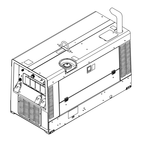
- Page 1 Visit our website at www.MillerWelds.com Big Blue 300 P OM-4433 218 314P 2007−11 Processes Stick (SMAW) Welding TIG (GTAW) Welding MIG (GMAW) Welding Flux Cored (FCAW) Welding Air Carbon Arc (CAC-A) Cutting and Gouging Description Engine Driven Welding Generator ®...
- Page 2 ISO 9001:2000 Quality System Standard. particular model are also provided. Miller Electric manufactures a full line of welders and welding related equipment. For information on other quality Miller products, contact your local Miller distributor to receive the latest full line catalog or individual specification sheets.
-
Page 3: Table Of Contents
TABLE OF CONTENTS SECTION 1 − SAFETY PRECAUTIONS − READ BEFORE USING 1-1. Symbol Usage ............... . 1-2. - Page 4 TABLE OF CONTENTS 8-5. Servicing Engine Cooling System 8-6. Adjusting Engine Speed On Standard Models 8-7. Adjusting Engine Speed On Models With Automatic Idle (Optional) 8-8. Servicing Fuel And Lubrication Systems 8-9. Overload Protection ..............8-10.
-
Page 5: Section 1 − Safety Precautions − Read Before Using
SECTION 1 − SAFETY PRECAUTIONS − READ BEFORE USING Protect yourself and others from injury — read and follow these precautions. 1-1. Symbol Usage DANGER! − Indicates a hazardous situation which, if not avoided, will result in death or serious injury. The possible hazards are shown in the adjoining symbols or explained in the text. - Page 6 FUMES AND GASES can be hazardous. Welding produces fumes and gases. Breathing these fumes and gases can be hazardous to your health. D Keep your head out of the fumes. Do not breathe the fumes. D If inside, ventilate the area and/or use local forced ventilation at the arc to remove welding fumes and gases.
-
Page 7: Engine Hazards
1-3. Engine Hazards BATTERY EXPLOSION can BLIND. D Always wear a face shield, rubber gloves, and protective clothing when working on a battery. D Stop engine before disconnecting or connect- ing battery cables or servicing battery. D Do not allow tools to cause sparks when working on a battery. D Do not use welder to charge batteries or jump start vehicles. -
Page 8: Additional Symbols For Installation, Operation, And Maintenance
HOT METAL from air arc cutting and gouging can cause fire or explosion. D Do not cut or gouge near flammables. D Watch for fire; keep extinguisher nearby. HOT PARTS can cause burns and injury. D Do not touch hot compressor or air system parts. -
Page 9: California Proposition 65 Warnings
H.F. RADIATION can cause interference. D High-frequency (H.F.) can interfere with radio navigation, safety services, computers, and communications equipment. D Have only qualified persons familiar with electronic equipment perform this installation. D The user is responsible for having a qualified electrician promptly correct any interference problem resulting from the installation. -
Page 10: Section 2 − Consignes De Sécurité − Lire Avant Utilisation
SECTION 2 CONSIGNES DE SÉCURITÉ − LIRE AVANT − Se protéger, ainsi que toute autre personne travaillant sur les lieux, contre les étincelles et le métal chaud. 2-1. Signification des symboles DANGER! − Indique une situation dangereuse qui si on l’évite pas peut donner la mort ou des blessures graves. - Page 11 DES PIÈCES CHAUDES peuvent provoquer des brûlures graves. D Ne pas toucher à mains nues les parties chau- des. D Prévoir une période de refroidissement avant de travailler à l’équipement. D Ne pas toucher aux pièces chaudes, utiliser les outils recomman- dés et porter des gants de soudage et des vêtements épais pour éviter les brûlures.
-
Page 12: Dangers Existant En Relation Avec Le Moteur
LES CHAMPS MAGNETIQUES peuv- ent affecter des implants médicaux. D Porteur de simulateur cardiaque ou autre im- plants médicaux, rester à distance. D Les porteurs d’implants doivent d’abord consulter leur médecin avant de s’approcher des opérations de soudage à l’arc, de sou- dage par points, de gougeage, du coupage plasma ou de chauf- fage par induction. -
Page 13: Dangers Liés À L'air Comprimé
L’utilisation d’un groupe autonome à l’intérieur PEUT VOUS TUER EN QUELQUES MINUTES. D Les fumées d’un groupe autonome contient du monoxyde de carbone. C’est un poison invisi- ble et inodore. D JAMAIS utiliser dans une maison ou garage, même avec les portes et fenêtres ouvertes. D Uniquement utiliser à... - Page 14 LE SURCHAUFFEMENT peut endom- mager le moteur électrique. D Arrêter ou déconnecter l’équipement avant de démarrer ou d’arrêter le moteur. D Ne pas laisser tourner le moteur trop lentement sous risque d’en- dommager le moteur électrique à cause d’une tension et d’une fré- quence trop faibles.
-
Page 15: Proposition Californienne 65 Avertissements
2-6. Proposition californienne 65 Avertissements Les équipements de soudage et de coupage produisent des fumées et des gaz qui contiennent des produits chimiques dont l’État de Californie reconnaît qu’ils provoquent des mal- formations congénitales et, dans certains cas, des cancers. (Code de santé... -
Page 16: Section 3 − Definitions
SECTION 3 − DEFINITIONS 3-1. Warning Label Definitions 0 − 50 h Std. 50 h Std. Notes OM-4433 Page 12 S-177 571 DIESEL 200A 0 − 200A API CD-MIL L 2104D, CD/SE, CD/SF Remove unit from shipping crate. Remove Owner’s Manual from unit. -
Page 17: Manufacturer's Rating Label
3-2. Manufacturer’s Rating Label 228 417-B / 803 562-F OM-4433 Page 13... -
Page 18: Symbols And Definitions
3-3. Symbols And Definitions Some symbols are found only on CE products. Stop Engine Starting Aid (Preheat) Check Injectors/ Pump Positive Amperes Engine Stick (SMAW) Welding Time Three Phase Electrode Connection Duty Cycle Rated Idle Speed Contactor On OM-4433 Page 14 Fast (Run, Weld/ Power) Battery (Engine) -
Page 19: Section 4 − Specifications
SECTION 4 − SPECIFICATIONS 4-1. Weld, Power, And Engine Specifications Welding Weld Output Rated Welding Mode Range Output 400 A, 23 Volts DC, 40% Duty Cycle 20 − 410 A 410 A 300 A, 32 Volts DC 300 A, 32 Volts DC CC/DC CC/DC 60% Duty Cycle... -
Page 20: Volt-Ampere Curves
4-3. Volt-Ampere Curves A. Stick Mode B. MIG Mode C. TIG Mode OM-4433 Page 16 DC AMPERES DC AMPERES DC AMPERES The volt-ampere curves show the minimum and maximum voltage and amperage output capabilities of the welding generator. Curves of all other settings fall between the curves shown. -
Page 21: Fuel Consumption
4-4. Fuel Consumption 2.00 1.75 1.50 1.25 1.00 0.75 0.50 0.25 IDLE 0.00 DC WELD AMPERES AT 100% DUTY CYCLE 4-5. Duty Cycle And Overheating 1000 50 60 % DUTY CYCLE The curve shows typical fuel use under weld or power loads. 100% Duty Cycle Duty Cycle is percentage of 10 min- utes that unit can weld at rated load... -
Page 22: Ac Generator Power Curve
4-6. AC Generator Power Curve Notes OM-4433 Page 18 AC AMPERES IN 240 V MODE AC AMPERES IN 120 V MODE MATERIAL THICKNESS REFERENCE CHART The ac power curve shows the gen- erator power in amperes available at the 120 and 240 volt receptacles. 217 519 24 Gauge (.025 in) 22 Gauge (.031 in) -
Page 23: Section 5 − Installation
SECTION 5 − INSTALLATION 5-1. Installing Welding Generator Movement Location/Airflow Clearance 18 in (460 mm) 18 in (460 mm) 18 in (460 mm) (460 mm) Grounding GND/PE 18 in (460 mm) 18 in Always securely fasten weld- ing generator onto transport vehicle or trailer and comply with all DOT and other applica- ble codes. -
Page 24: Mounting Welding Generator
5-2. Mounting Welding Generator Supporting The Unit Inadequate support. Do not use flexible mounts. Using Mounting Brackets Tools Needed: 9/16 in OM-4433 Page 20 Welding Unit In Place Bolting Unit In Place install3 2007−04 803 274 / 200 864-A / 803 562 Do not weld on base. -
Page 25: Installing Exhaust Pipe
5-3. Installing Exhaust Pipe Tools Needed: 1/2 in Notes Stop engine and let cool. Point exhaust pipe in desired di- rection but always away from front panel and direction of travel. 803 582 / Ref. 217 357-A Work like a Pro! Pros weld and cut safely. -
Page 26: Activating The Dry Charge Battery (If Applicable)
5-4. Activating The Dry Charge Battery (If Applicable) 5 A For 30 Minutes 30 A For 12 Minutes Tools Needed: 5-5. Connecting The Battery Tools Needed: 1/2 in OM-4433 Page 22 − Always wear a face shield, rubber gloves and protective clothing when working on a battery. -
Page 27: Engine Prestart Checks
5-6. Engine Prestart Checks Full Diesel Full Check all engine fluids daily. Engine must be cold and on a level surface. Unit is shipped with 20W break-in oil. Automatic shutdown system stops engine if oil pressure is too low or coolant tempera- ture is too high. -
Page 28: Connecting To Weld Output Terminals
5-7. Connecting To Weld Output Terminals Stop engine. Work/Negative (−) Weld Output Terminal CV (wire) Weld Output Terminal CC (Stick/TIG) Weld Output Terminal Failure to properly connect weld cables may cause excessive heat and start a fire, or damage your machine. Weld Output Terminal Supplied Weld Output Terminal Nut Weld Cable Terminal... -
Page 29: Selecting Weld Cable Sizes
5-8. Selecting Weld Cable Sizes* Weld Output Terminals Terminals Stop engine before connecting to weld output terminals. Do not use worn, dam- aged, undersized, or poorly spliced cables. Welding Amperes This chart is a general guideline and may not suit all applications. If cables overheat, use next size larger cable. **Weld cable size (AWG) is based on either a 4 volts or less drop or a current density of at least 300 circular mils per ampere. -
Page 30: Connecting To Remote 14 Receptacle Rc14
5-9. Connecting To Remote 14 Receptacle RC14 LDR-14 long distance remote (includes 120 V receptacle) *The remaining sockets are not used. Notes OM-4433 Page 26 Socket* 24 volts ac. Protected by sup- plementary protector CB8. 24 VOLTS AC 24 VOLTS AC Contact closure to A completes 24 volt ac contactor control circuit. - Page 31 Notes Welding Symbols Ref. AWS/ANSI A2.4 OM-4433 Page 27...
-
Page 32: Section 6 − Operating Welding Generator
SECTION 6 − OPERATING WELDING GENERATOR 6-1. Front Panel Controls (See Section 6-2) 217 357-B / 803 563 OM-4433 Page 28... -
Page 33: Description Of Front Panel Controls (See Section 6-1)
6-2. Description Of Front Panel Controls (See Section 6-1) Engine Starting Controls Preheat Switch Use switch to energize starting aid for cold weather starting (see starting instructions fol- lowing). Engine Control Switch Use switch to start engine, select engine speed (if unit has auto idle option), and stop engine. -
Page 34: Process/Contactor Switch
6-3. Process/Contactor Switch Switch Setting Switch Setting Remote On/Off Switch Re- GTAW With HF Unit, Pulsing quired −TIG HF Required Or Device, Or Remote Control Scratch Start Remote On/Off Switch Stick (SMAW) With Remote On/Off Required − Stick Remote On/Off Switch MIG (GMAW) Required −... -
Page 35: Lift-Arct Start Procedure
6-4. Lift-Arc™ Start Procedure Lift-Arc Start Method “Touch” Do NOT Strike Like A Match! Notes 1 − 2 Seconds Lift-Arc t TIG With Lift-Arct TIG selected, start arc as follows: TIG Electrode Workpiece Turn gas on. Touch tungsten electrode to workpiece at weld start point. -
Page 36: Remote Voltage/Amperage Control
6-5. Remote Voltage/Amperage Control In Example: Min = 20 A DC Max = 205 A DC Connect Remote Control To Remote Receptacle RC14 Set TIG or STICK Process Connect Remote Control To Remote Receptacle RC14 Set WIRE Process OM-4433 Page 32 Remote 14 Receptacle RC14 Connect optional remote control to RC14 (see Section 5-9). -
Page 37: Section 7 − Operating Auxiliary Equipment
SECTION 7 − OPERATING AUXILIARY EQUIPMENT 7-1. Generator Power Receptacles 120 V 20 A AC (shown) Receptacle RC5 and/or GFCI1 120 V 20 A AC GFCI (shown) Receptacle RC6 and/or GFCI2 240 V 50 A AC Receptacle RC11 RC5 / 6 and GFCI1 / 2 supply 60 Hz single- phase power at weld/power speed. -
Page 38: Section 8 − Maintenance & Troubleshooting
SECTION 8 − MAINTENANCE & TROUBLESHOOTING 8-1. Routine Maintenance n = Check Z = Change * To be done by Factory Authorized Service Agent Every Hours n Coolant Level n Fuel Level Every Hours ~ Weld Terminals Every Hours ~ Battery Terminals n Air Cleaner Hoses Every Hours... -
Page 39: Maintenance Label
8-2. Maintenance Label OM-4433 Page 35... -
Page 40: Servicing Air Cleaner
8-3. Servicing Air Cleaner Keep nozzle 2 in (51 mm) from element. Blow OM-4433 Page 36 Optional Inspect aircleaner1 2/01− ST-153 929-B / ST-153 585 / Ref. S-0698-B / Ref. 217 357-A Stop engine. NOTICE − Do not run engine without air cleaner or with dirty element. -
Page 41: Inspecting And Cleaning Optional Spark Arrestor Muffler
8-4. Inspecting And Cleaning Optional Spark Arrestor Muffler 8-5. Servicing Engine Cooling System Stop engine and let cool. Tools Needed: Spark Arrestor Muffler 3/8 in Cleanout Plug Remove plug and remove any dirt covering cleanout hole. Exhaust Pipe Start engine and run at idle speed to blow out cleanout hole. -
Page 42: Adjusting Engine Speed On Standard Models
8-6. Adjusting Engine Speed On Standard Models Engine Speed RPM (Hz) (No Load) 1880 (61.7) Weld/Power Maximum OM-4433 Page 38 Stop engine and let cool. Engine speed is factory set and should not require adjustment. Af- ter tuning engine, check engine speed with tachometer or frequen- cy meter. -
Page 43: Adjusting Engine Speed On Models With Automatic Idle (Optional)
8-7. Adjusting Engine Speed On Models With Automatic Idle (Optional) Engine Speed (No Load) 1880 rpm max (62.6 Hz) 1500 rpm (50 Hz) To prevent solenoid damage, be sure a 1/8 in (3 mm) gap exists be- tween the engine low speed screw throttle lever when the... -
Page 44: Servicing Fuel And Lubrication Systems
8-8. Servicing Fuel And Lubrication Systems OM-4433 Page 40 Stop engine and let cool. After servicing, start engine and check for fuel leaks. Stop engine, tighten connec- tions as necessary, and wipe up spilled fuel. Oil Filter Oil Drain Valve And Hose Oil Fill Cap Primary (Canister) Fuel Filter Secondary (In-Line) Fuel... -
Page 45: Overload Protection
8-9. Overload Protection Stop engine. When a circuit breaker, supple- mentary protector, opens, it usually indicates a more serious problem exists. Contact Factory Service Agent. Fuse F1 F1 protects the stator exciter wind- ing from overload. If F1 opens, weld and generator power is low or stops entirely. -
Page 46: Checking Generator Brushes
8-10. Checking Generator Brushes Notes OM-4433 Page 42 5/16 in. (8 mm) Minimum Length 9/16 in. (14.3 mm) New Length Replace Damaged Brushes MATERIAL THICKNESS REFERENCE CHART Stop engine and let cool. Generator Brush With Spring Mark and disconnect leads at brush hold- er cap. -
Page 47: Voltmeter/Ammeter Help Displays
8-11. Voltmeter/Ammeter Help Displays HL.P HL.P HL.P HL.P HL.P HL.P Use the Voltmeter/Ammeter help displays to diagnose and correct fault conditions. Indicates a failure of meter display module PC2, or the wiring between PC2 and main control module PC1. If this display is shown, have Facto- ry Authorized Service Agent check PC1, PC2, and the wiring between PC1 and PC2. -
Page 48: Troubleshooting
8-12. Troubleshooting Also see Voltmeter/Ammeter help displays to assist in troubleshooting weld problems (see Section 8-11). A. Welding Trouble No weld output; generator power output Place Process/Contactor switch in a Weld Terminals Always On position, or place switch in a Remote okay at ac receptacles. - Page 49 B. Generator Power Trouble No generator power output at ac recep- Reset receptacle supplementary protector(s) (see Section 7-1). tacles; weld output okay. No generator power or weld output. Disconnect equipment from generator power receptacles during start-up. Check fuse F1, and replace if open (see Section 8-9). Have Factory Authorized Service Agent check vol- tage regulator module PC3.
- Page 50 Trouble Engine slowly stopped and cannot be Check fuel level. restarted. Check engine air and fuel filters (see Sections 8-3 and 8-8). See engine manual. Battery discharges between uses. Turn Engine Control switch off when unit is not running. Clean top of battery with baking soda and water solution; rinse with clear water. Recharge or replace battery if necessary.
- Page 51 Notes MATERIAL THICKNESS REFERENCE CHART 24 Gauge (.025 in) 22 Gauge (.031 in) 20 Gauge (.037 in) 18 Gauge (.050 in) 16 Gauge (.063 in) 14 Gauge (.078 in) 1/8 in (.125 in) 3/16 in (.188 in) 1/4 in (.25 in) 5/16 in (.313 in) 3/8 in (.375 in) 1/2 in (.5 in)
-
Page 52: Circuit Diagram For Welding Generator
SECTION 9 − ELECTRICAL DIAGRAMS Figure 9-1. Circuit Diagram For Welding Generator OM-4433 Page 48... - Page 53 219 228−E OM-4433 Page 49...
-
Page 54: Section 10 − Run-In Procedure
SECTION 10 − RUN-IN PROCEDURE 10-1. Wetstacking OM-4433 Page 50 run_in1 2007−04 NOTICE − Do not perform run-in procedure at less than 20 volts weld output and do not exceed duty cycle or equipment damage may occur. Welding Generator Run diesel engines near rated volt- age and current during run-in period to properly seat piston rings and prevent wetstacking. -
Page 55: Run-In Procedure Using Load Bank
10-2. Run-In Procedure Using Load Bank Stop engine. Do not touch hot exhaust pipe, engine parts, or load bank/grid. Keep exhaust and pipe away from flammables. NOTICE − Do not perform run-in procedure at less than 20 volts weld output and do not exceed duty cycle or equipment damage may occur. -
Page 56: Run-In Procedure Using Resistance Grid
10-3. Run-In Procedure Using Resistance Grid OM-4433 Page 52 Stop engine. Do not touch hot exhaust pipe, engine parts, or load bank/grid. Keep exhaust and pipe away from flammables. NOTICE − Do not perform run-in procedure at less than 20 volts weld output and do not exceed duty cycle or equipment damage may occur. -
Page 57: Section 11 − Generator Power Guidelines
SECTION 11 − GENERATOR POWER GUIDELINES The views in this section are intended to be representative of all engine-driven welding generators. Your unit may differ from those shown. 11-1. Selecting Equipment 11-2. Grounding Generator To Truck Or Trailer Frame GND/PE Generator Power Receptacles −... -
Page 58: Grounding When Supplying Building Systems
11-3. Grounding When Supplying Building Systems 11-4. How Much Power Does Equipment Require? OM-4433 Page 54 GND/PE VOLTS 115 AMPS Equipment Grounding Terminal Grounding Cable Use #10 AWG or larger insulated copper wire. Ground Device Use ground device as stated in electrical codes. - Page 59 11-5. Approximate Power Requirements For Industrial Motors Industrial Motors Split Phase Capacitor Start-Induction Run Capacitor Start-Capacitor Run Fan Duty 11-6. Approximate Power Requirements For Farm/Home Equipment Farm/Home Equipment Stock Tank De-Icer Grain Cleaner Portable Conveyor Grain Elevator Milk Cooler Milker (Vacuum Pump) FARM DUTY MOTORS Std.
- Page 60 11-7. Approximate Power Requirements For Contractor Equipment Contractor Hand Drill Circular Saw Table Saw Band Saw Bench Grinder Air Compressor Electric Chain Saw Electric Trimmer Electric Cultivator Elec. Hedge Trimmer Flood Lights Submersible Pump Centrifugal Pump Floor Polisher High Pressure Washer 55 gal Drum Mixer Wet &...
- Page 61 11-8. Power Required To Start Motor Motor Start Code KVA/HP 11-9. How Much Power Can Generator Supply? Single-Phase Induction Motor Starting Requirements 10.0 AC MOTOR VOLTS AMPS CODE PHASE 11.2 12.5 Motor Start Code Running Amperage Motor HP Motor Voltage To find starting amperage: Step 1: Find code and use table to find kVA/HP.
- Page 62 11-10. Typical Connections To Supply Standby Power Utility Electrical Transfer Switch Service Essential Loads OM-4433 Page 58 Fused Welding Disconnect Generator Switch Output (If Required) Have only qualified persons perform these connections according to all applicable codes and safety practices. Properly install and ground this equipment according to its Owner’s Manual and na-...
- Page 63 11-11. Selecting Extension Cord (Use Shortest Cord Possible) Cord Lengths for 120 Volt Loads If unit does not have GFCI receptacles, use GFCI-protected extension cord. Current Load (Watts) (Amperes) 1200 1800 2400 3000 3600 4200 4800 5400 6000 *Conductor size is based on maximum 2% voltage drop Cord Lengths for 240 Volt Loads If unit does not have GFCI receptacles, use GFCI-protected extension cord.
-
Page 64: Section 12 − Parts List
SECTION 12 − PARTS LIST Hardware is common and not available unless listed. Wirng harnesses are listed at the end of parts section. 4 (Fig.12−5) 110 (Fig.12−3) 108 (Fig.12−2) OM-4433 Page 60 Figure 12-1. Main Assembly 23 24... - Page 65 80(Fig.12−4) 803 683-F OM-4433 Page 61...
- Page 66 Item Dia. Part Mkgs... . 168829 ... . . 213027 ....217070 .
- Page 67 Item Dia. Part Mkgs....199592 ....+213487 ....191626 .
- Page 68 Item Dia. Part Mkgs..... 172071 ....211961 .
- Page 69 Hardware is common and not available unless listed. Wirng harnesses are listed at the end of parts section. Item Dia. Part Mkgs. Figure 12-2. Panel, Front w/Components (Figure 12-1 Item 108) ....097926 .
- Page 70 Item Dia. Part Mkgs. Figure 12-2. Panel, Front w/Components (Continued) ....214543 ....134201 .
- Page 71 Hardware is common and not available unless listed. Wirng harnesses are listed at the end of parts section. Item Dia. Part Mkgs. Figure 12-3. Control Panel (Figure 12-1 Item 110) ....220981 .
- Page 72 Hardware is common and not available unless listed. Wirng harnesses are listed at the end of parts section. Item Dia. Part Mkgs..ROTOR . . . 212474 ....053390 .
- Page 73 Hardware is common and not available unless listed. Wirng harnesses are listed at the end of parts section. Item Dia. Part Mkgs..... 217081 .
- Page 74 Some wiring harness components (switches, relays, supplementary protectors) are also referenced elsewhere in this parts list. Purchase compo- nents separately or as part of the associated wiring harness. Item Dia. Part Mkgs..... 231122 .
- Page 75 Warranty Questions? LIMITED WARRANTY − Subject to the terms and conditions Call below, Miller Electric Mfg. Co., Appleton, Wisconsin, warrants to 1-800-4-A-MILLER its original retail purchaser that new Miller equipment sold after the effective date of this limited warranty is free of defects in for your local material and workmanship at the time it is shipped by Miller.
- Page 76 For assistance in filing or settling claims, contact your distributor and/or equipment manufacturer’s Transportation Department. © 2007 Miller Electric Mfg. Co. 2007−01 Miller Electric Mfg. Co. An Illinois Tool Works Company 1635 West Spencer Street Appleton, WI 54914 USA International Headquarters−USA...