Miele CS 1212-1 Operating And Installation Instructions
Ceramic hobs with induction
Hide thumbs
Also See for CS 1212-1:
- Operating and installation instructions (60 pages) ,
- Operating and installation instructions (60 pages) ,
- Operating and installation instructions (60 pages)
Table of Contents

Related Manuals for Miele CS 1212-1


Summary of Contents for Miele CS 1212-1
- Page 1 Operating and installation instructions Ceramic hobs with induction To avoid the risk of accidents or damage to the appliance it is essential to read these instructions before it is installed and used for the first time. en-GB M.-Nr. 09 055 450...
-
Page 2: Table Of Contents
Contents Warning and Safety instructions................ 4 Caring for the environment ................ 14 Guide to the appliance .................. 15 Hob........................15 CS 1212-1 ...................... 15 CS 1221-1 ...................... 16 CS 1222...................... 17 Indicators....................... 17 Control symbols ....................18 Display........................18 Cooking zones....................... 18 Using for the first time .................. - Page 3 Optional accessories .................. 38 Safety instructions for installation.............. 39 Safety distances .................... 40 Installation notes .................... 44 Building-in dimensions .................. 45 CS 1212-1 ......................45 CS 1221-1 / CS 1222 .................... 46 Building-in several CombiSets ................ 47 Installation...................... 49 Electrical connection .................. 53 After sales service, plate, guarantee ..............
-
Page 4: Warning And Safety Instructions
They contain important notes on in- stallation, safety, use and maintenance. Miele cannot be held liable for damage caused by non-compliance with these instructions. Keep these instructions in a safe place and ensure that new users... - Page 5 Warning and Safety instructions Correct application This hob is intended for domestic use and use in other similar en- vironments. This hob is not intended for outdoor use. It is intended for domestic use only to cook food and keep it warm.
- Page 6 Warning and Safety instructions Safety with children Children under 8 years of age must be kept away from the hob unless they are constantly supervised. Children 8 years and older may only use the hob unsupervised if they have been shown how to use it in a safe way and can recognise and understand the consequences of incorrect operation.
- Page 7 Unauthorised installation, maintenance and repairs can cause considerable danger for the user. Installation, maintenance and re- pairs must only be carried out by a Miele authorised technician. Do not use a damaged appliance. It could be dangerous. Check the hob for visible signs of damage.
- Page 8 Warning and Safety instructions Miele can only guarantee the safety of the appliance when genu- ine original Miele replacement parts are used. Faulty components must only be replaced by Miele spare parts. The hob is not intended for use with an external timer switch or a remote control system.
- Page 9 Warning and Safety instructions Correct use The hob gets hot when in use and remains hot for a while after be- ing switched off. There is a danger of burning until the residual heat indicators go out. Oil and fat can overheat and catch fire. Do not leave the hob unat- tended when cooking with oil and fat.
- Page 10 Warning and Safety instructions You could burn yourself on the hot hob. Protect your hands with heat-resistant pot holders or gloves when handling hot pots and pans. Do not let them get wet or damp, as this causes heat to trans- fer through the material more quickly with the risk of scalding or burning yourself.
- Page 11 Warning and Safety instructions Induction heating works extremely quickly and so the base of the pan could heat up to the temperature at which oil or fat self-ignites within a very short time. Do not leave the hob unattended whilst it is being used.
- Page 12 Warning and Safety instructions Where several CombiSets are installed side by side: Hot objects can damage the seal of the cover strip between the ap- pliances. Do not place hot pans near or on the cover strip.
-
Page 13: Cleaning And Care
Warning and Safety instructions Cleaning and care Do not use a steam cleaning appliance to clean this hob. The steam could reach electrical components and cause a short cir- cuit. If the hob is built in over a pyrolitic oven, the hob should not be used whilst the pyrolitic process is being carried out, as this could trigger the overheating protection mechanism on the hob (see relev- ant section). -
Page 14: Caring For The Environment
Caring for the environment Disposal of the packing mater- Disposal of your old appliance Electrical and electronic appliances of- ten contain valuable materials. They The packaging is designed to protect also contain materials which, if handled the appliance from damage during or disposed of incorrectly, could be po- transportation. -
Page 15: Guide To The Appliance
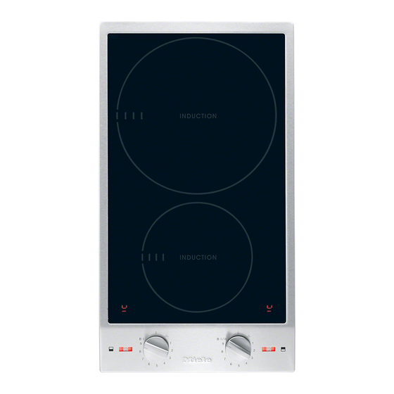
Guide to the appliance CS 1212-1 a Cooking zone with TwinBooster b Cooking zone with Booster c Cooking zone display d Cooking zone symbols e Indicators f Control for the rear cooking zone g Control for the front cooking zone... - Page 16 Guide to the appliance CS 1221-1 a Cooking zone with TwinBooster b Cooking zone display c Indicators d Cooking zone controls...
-
Page 17: Indicators
Guide to the appliance CS 1222 a Extended zone with TwinBooster b Cooking zone with Booster c Cooking zone display d Cooking zone symbols e Indicators g Control for the front cooking zone h Control for the rear cooking zone Indicators ... -
Page 18: Control Symbols
The system lock has been activated / Safety switch-off (see "Safety features") Overheating protection (see "Safety features") Cooking zones Cooking zone CS 1212-1 Ø in cm* Rating in watts for 230 V** 10–16 Normal 1400 Booster 2200 ... - Page 19 Guide to the appliance CS 1221-1 Ø in cm* Rating in watts for 230 V** 18–28 Normal 2600 TwinBooster, level 1 3000 TwinBooster, level 2 3700 * Pans with a base diameter within the given range may be used. ** The wattage quoted may vary depending on the size and material of the pans used. Cooking zone CS 1222 Ø in cm*...
-
Page 20: Using For The First Time
Using for the first time Please stick the extra data plate for Switching on the hob for the the appliance supplied with this doc- first time umentation in the space provided in the "After sales service, data plate, When the hob is first connected, or guarantee"... -
Page 21: Induction
Induction The induction principle When the appliance is switched on either deliberately or by mistake, An induction coil is located under each or when there is residual heat cooking zone. When a cooking zone is present, there is the risk of any metal switched on, this coil creates a mag- items placed on the hob (e.g. -
Page 22: Noises
Induction Noises When using an induction cooking zone, the following noises can occur in the pan, depending on what it is made of and how it has been constructed. On the higher power settings, it might buzz. This will decrease or cease alto- gether when the power setting is re- duced. -
Page 23: Pans
Induction – Often the maximum diameter quoted Pans by manufacturers refers to the dia- The following pan types are suitable: meter of the top rim of the pot or pan. The diameter of the base (gener- – stainless steel with a base that can ally smaller) is the more important be magnetised, one. -
Page 24: Tips On Saving Energy
Tips on saving energy – Use a lid whenever possible to min- imise heat loss. – Select a smaller pan when cooking small quantities. A smaller pan uses less energy than a larger pan with very little in it. – Cook with as little water as possible. –... -
Page 25: Settings
Settings Setting range Keeping warm Melting butter Dissolving gelatine Melting chocolate Making milk puddings Warming small quantities of liquid Cooking rice Defrosting frozen vegetables Making porridge Warming liquid and semi-solid food Making omelettes or lightly frying eggs Steaming fruit Cooking dumplings Steaming vegetables and fish Defrosting and reheating frozen food... -
Page 26: Operation
Operation Switching off Fire hazard. Do not leave the hob unattended Turn the cooking zone control anti- whilst it is being used. clockwise to 0. Please note that the heating up time When all cooking zones are switched on induction hobs is very much off the in-operation indicator will go shorter than on conventional hobs. -
Page 27: Auto Heat-Up
Operation Auto heat-up Continued cook- Heat-up time ing setting [min : sec] When Auto heat-up has been activated, the cooking zone switches on automat- approx. 0 : 15 ically at the highest power setting and approx. 0 : 15 then switches to the continued cooking setting. -
Page 28: Booster
Operation Cooking zones are linked in pairs to Booster supply the power for the booster func- The cooking zones are equipped with a tion. Booster with one level or a TwinBooster When the booster function is selected, with two levels (see "Guide to the appli- a proportion of energy is taken away ance - Hob"). - Page 29 Operation To switch on the Booster To switch off the Booster / Twin- Booster Turn the cooking zone control clock- Select a different power level. wise past 9 to B I and back again to 9. The Booster symbol and "B" will go out. ...
-
Page 30: Keeping Warm
Operation Setting the keeping warm function Keeping warm Turn the control clockwise to . The keeping warm function is for keeping food that has just been cooked warm, i.e. food that is still hot. It is not for reheating food that has gone cold. -
Page 31: Safety Features
Safety features System lock Safety switch-off The safety switch-off mechanism is The system lock can only be activated triggered automatically if one of the if all the cooking zones are switched cooking zones is heated for an unusu- off. ally long period of time. This period of time depends on the power level selec- Your hob is equipped with a system lock to prevent the cooking zones being... -
Page 32: Overheating Protection
If, despite removing the cause, the – The cooking zone will switch off overheating protection mechanism trig- automatically. will flash in the cook- gers again, contact Miele. ing zone display. – Further cooking zones switch off automatically. Switch off the affected cooking zone. -
Page 33: Cleaning And Care
Cleaning and care Allow the CombiSet to cool down Danger of burning. before cleaning. The cooking zones must be switched off. The hob must have cooled down. The CombiSet and accessories should be cleaned after each use. Danger of injury. -
Page 34: Ceramic Surface
Wipe all coarse soiling off using a damp cloth. Stubborn soiling may need to be removed with a shielded scraper blade. Then clean the hob with Miele ceramic and stainless steel hob cleaner (see "Optional accessories") or a suitable proprietary ceramic hob cleaning agent applied with kitchen paper or a clean cloth. -
Page 35: Stainless Steel Frame/Control Panel
Cleaning and care Stainless steel frame/control panel Clean the frame and the control panel with a solution of warm water and a little washing-up liquid applied with a soft sponge. You can also use a ceramic and stain- less steel cleaning agent. We recom- mend also using a stainless steel condi- tioning agent to help prevent resoiling (see "Optional accessories). -
Page 36: Problem Solving Guide
Danger of injury. Installation, maintenance and repairs may only be carried out by a suitably qualified and competent person. Repairs and other work by unqualified persons could be dangerous. Miele can- not be held liable for unauthorised work. Do not attempt to open the casing of the CombiSet yourself. - Page 37 Problem solving guide Problem Cause and remedy flashes alternately The power level set has been reduced because the with the power level in a Booster function on the linked cooking zone has cooking zone display. been activated (see "Booster"). flashes alternately There has been no pan, or an unsuitable pan, on the with ...
-
Page 38: Optional Accessories
These can be ordered online at: Removes heavy soiling, limescale de- posits and aluminium residues Stainless steel conditioning or from Miele (see end of this booklet agent 250 ml for contact details). Removes water marks, flecks and finger prints. Helps keep the appliance looking good for longer. -
Page 39: Safety Instructions For Installation
Safety instructions for installation The CombiSet must only be installed and connected to the electricity sup- ply by a suitably qualified and competent person in strict accordance with cur- rent national and local safety regulations. Fit the wall units and cooker hood before fitting the CombiSet to avoid dam- aging it. -
Page 40: Safety Distances
Safety distances Safety distance above the CombiSet A minimum safety distance must be maintained between the CombiSet and the cooker hood above it. See the cooker hood manufacturer's operating and installation instructions for details. If the manufacturer's instructions are not available for the cooker hood a min- imum safety distance of at least 760 mm must be maintained, or if any flammable objects (e.g. - Page 41 Minimum distance between the worktop cut-out and a tall unit or wall to the right or left of it: 40 mm CS 1212 / CS 1212-1 CS 1221 / CS 1221-1 CS 1234 / CS 1234-1 CS 1223 CS 1222...
- Page 42 Safety distances Minimum safety distances un- Interim shelf derneath the hob It is not necessary to fit an interim shelf underneath the hob but one may be fit- To ensure sufficient ventilation to the ted if you wish. hob, a certain gap must be left between the underside of the hob and any oven, Leave a gap of 10 mm at the back of interim shelf or drawer.
- Page 43 Safety distances Safety distance when installing the appliance near a wall with additional niche cladding A minimum safety distance must be maintained between the worktop cut-out and any niche cladding to protect it from heat damage. If the niche cladding is made from a combustible material (e.g. wood) a minimum safety distance ...
-
Page 44: Installation Notes
Installation notes Seal between the CombiSet Tiled worktop and the worktop Grout lines and the hatched area un- derneath the CombiSet frame must be smooth and even. If they are not the Do not use sealant between the CombiSet will not sit flush with the CombiSet and the worktop. -
Page 45: Building-In Dimensions
Building-in dimensions CS 1212-1 a Spring clamps b Front c Casing depth d Casing depth including mains connection box with mains connection cable, L = 2000 mm... - Page 46 Building-in dimensions CS 1221-1 / CS 1222 a Spring clamps b Front c Casing depth d Casing depth including mains connection box with mains connection cable, L = 2000 mm...
-
Page 47: Building-In Several Combisets
Building-in several CombiSets Example: 3 CombiSets a Spring clamps b Spacer bars c Gaps between spacer bars and worktop d Cover strips e CombiSet width minus 8 mm f CombiSet width g CombiSet width minus 8 mm h Worktop cut-out... - Page 48 Building-in several CombiSets Calculating the worktop cut-out The frames of the CombiSets overlap the worktop at the outside right and left by 8 mm on each side. Add up the widths of the CombiSets and subtract 16 mm from this figure. Example: 288 mm + 288 mm + 380 mm = 956 mm - 16 mm = 940 mm The CombiSets are 288 mm, 380 mm or 576 mm wide depending on model (see...
-
Page 49: Installation
Installation Preparing the worktop Make the worktop cut-out as shown in "Building-in dimensions" or as cal- culated (see Building several CombiSets). Observe the safety dis- tances (see "Safety distances"). Wooden worktops Seal the cut surfaces with a suitable sealant to avoid swelling caused by moisture. - Page 50 Installation Natural stone worktops You will need heavy duty double-side tape (not supplied) to secure the spring clamps and spacer bars. Apply silicone to the side and lower edges of the spring clamps and the spacer bars . Then fill gap between spacer bar ...
- Page 51 Installation Building in several CombiSets Installing the CombiSet Push the built-in CombiSet to the Feed the mains connection cable side until the holes in the spacer bar down through the cut-out. can be seen. Starting at the front, position the CombiSet in the worktop cut-out.
- Page 52 Installation Connecting the CombiSet Connect the CombiSet(s) to the mains. Check that each CombiSet works. Removing the CombiSet If the CombiSet cannot be accessed from below, you will need a special tool to remove it. If the CombiSet can be accessed from below, push it out from below.
-
Page 53: Electrical Connection
Residual current device Danger of injury. For extra safety, it is advisable to pro- Miele cannot be held liable for unau- tect the CombiSet with a suitable resid- thorised installation, maintenance ual current device (RCD) with a trip and repair work as this can be dan- range of 30 mA. - Page 54 If the mains cable needs to be replaced it must be replaced with a special con- Safety fuses nection cable, type H 05 VV-F (PVC-in- sulated), available from Miele. Completely remove fuses The connection data is quoted on the Automatic circuit breakers data plate.
-
Page 55: After Sales Service, Plate, Guarantee
N.B. A call-out charge will be applied to service visits where the problem could have been resolved as described in these instructions. When contacting your Dealer or Miele, please quote the model and serial number of your appliance. Data plate Space in which to stick the extra data plate supplied with the appliance. -
Page 56: Product Data Sheets
Information for domestic electric hobs In acc. with regulation (EU) No. 66/2014 MIELE Model name / identifier CS 1212-1 Number of cooking zones and/or areas For circular cooking zones: diameter of useful sur- 1. = Ø 100-160 mm face area/cooking zone 2. - Page 57 Product data sheets MIELE Model name / identifier CS 1222 Number of cooking zones and/or areas For circular cooking zones: diameter of useful sur- 1. = Ø 100-160 mm face area/cooking zone 2. = Ø 200 / 200x300 mm For non-circular cooking zones or areas: length 3.
- Page 59 Citywest Business Campus, Dublin 24 Dubai Tel: (01) 461 07 10, Fax: (01) 461 07 97 Tel: +971-4-341 84 44 E-Mail: info@miele.ie, Internet: www.miele.ie Fax: +971-4-341 88 52 Manufacturer: Miele & Cie. KG E-Mail: info@miele.ae Carl-Miele-Straße 29, 33332 Gütersloh, Germany Internet: www.miele.ae...
- Page 60 CS 1212-1 / CS 1221-1 / CS 1222 en-GB M.-Nr. 09 055 450 / 03...