
Related Manuals for Miller Electric 375


Summary of Contents for Miller Electric 375
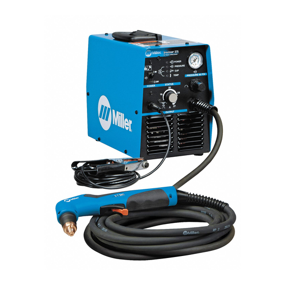
- Page 1 Spectrum 375 Visit our website at www.MillerWelds.com And ICE-27C Torch OM-2229 200 879N December 2004 Processes Air Plasma Cutting and Gouging Description Air Plasma Cutter And Non-CE Models...
- Page 2 ISO 9001:2000 Quality System Standard. particular model are also provided. Miller Electric manufactures a full line of welders and welding related equipment. For information on other quality Miller products, contact your local Miller distributor to receive the latest full line catalog or individual catalog sheets.
-
Page 3: Table Of Contents
TABLE OF CONTENTS SECTION 1 − SAFETY PRECAUTIONS - READ BEFORE USING 1-1. Symbol Usage ............... . 1-2. - Page 4 Declaration of Conformity for European Community (CE) Products NOTE This information is provided for units with CE certification (see rating label on unit). Miller Electric Mfg. Co. Manufacturer’s Name: 1635 W. Spencer Street Manufacturer’s Address: Appleton, WI 54914 USA SPECTRUM...
-
Page 5: Section 1 − Safety Precautions - Read Before Using
SECTION 1 − SAFETY PRECAUTIONS - READ BEFORE USING 1-1. Symbol Usage Means Warning! Watch Out! There are possible hazards with this procedure! The possible hazards are shown in the adjoining symbols. Y Marks a special safety message. Means “Note”; not safety related. 1-2. - Page 6 EXPLODING PARTS can injure. D On inverter power sources, failed parts can ex- plode or cause other parts to explode when power is applied. Always wear a face shield and long sleeves when servicing inverters. FLYING SPARKS can cause injury. Sparks and hot metal blow out from the cutting arc.
-
Page 7: Additional Symbols For Installation, Operation, And Maintenance
1-3. Additional Symbols For Installation, Operation, And Maintenance HOT PARTS can cause severe burns. D Do not touch hot parts bare handed. D Allow cooling period before working on torch. MOVING PARTS can cause injury. D Keep away from moving parts such as fans. D Keep all doors, panels, covers, and guards closed and securely in place. -
Page 8: Principal Safety Standards
1-5. Principal Safety Standards Safety in Welding and Cutting, ANSI Standard Z49.1, from American Welding Society, 550 N.W. LeJeune Rd, Miami FL 33126 Safety and Health Standards, OSHA 29 CFR 1910, from Superinten- dent of Documents, U.S. Government Printing Office, Washington, D.C. 20402. -
Page 9: Section 2 − Consignes De Sécurité − Lire Avant Utilisation
SECTION 2 − CONSIGNES DE SÉCURITÉ − LIRE AVANT UTILISATION 2-1. Signification des symboles Signifie Mise en garde ! Soyez vigilant ! Cette procédure présente des risques de danger ! Ceux-ci sont identifiés par des symboles adjacents aux directives. Y Identifie un message de sécurité particulier. Signifie NOTA ;... - Page 10 Isoler la pince de masse quand pas mis à la pièce pour éviter le contact avec tout objet métallique. Il y a DU COURANT CONTINU IMPORTANT dans les convertisseurs après la suppression de l’ali- mentation électrique. D Arrêter les convertisseurs, débrancher le courant électrique, et dé- charger les condensateurs d’alimentation selon les instructions indiquées dans la partie entretien avant de toucher les pièces.
-
Page 11: Dangers Supplémentaires En Relation Avec L'installation, Le Fonctionnement Et La Maintenance
LES BOUTEILLES peuvent exploser si elles sont endommagées. Les bouteilles de gaz contiennent du gaz sous haute pression. Si une bouteille est endommagée, elle peut exploser. Puisque les bouteilles de gaz font habituellement partie d’un processus de travail des métaux, assurez−vous de les manipuler correctement. -
Page 12: Principales Normes De Sécurité
2-4. Principales normes de sécurité Safety in Welding and Cutting, norme ANSI Z49.1, de l’American Wel- ding Society, 550 N.W. Lejeune Rd, Miami FL 33126 Safety and Health Sandards, OSHA 29 CFR 1910, du Superintendent of Documents, U.S. Government Printing Office, Washington, D.C. 20402. -
Page 13: Section 3 − Definitions
SECTION 3 − DEFINITIONS 3-1. Warning Label Definitions Warning! Watch Out! There are possible hazards as shown by the symbols. Cutting sparks can cause explosion or fire. 1.1 Keep flammables away from cutting. Do not cut near flammables. 1.2 Cutting sparks can cause fires. -
Page 14: Symbols And Definitions For Nameplate And Serial Number/Rating Label
3-2. Symbols And Definitions For Nameplate And Serial Number/Rating Label Amperes Volts Protective Earth (Ground) Rated No Load Voltage (Average) Rated Maximum 1max Supply Current Degree Of Protection Maximum Effective 1eff Supply Current OM-2229 Page 10 Plasma Arc Cutting (PAC) Increase Single Phase Conventional Load... -
Page 15: Section 4 − Installation
SECTION 4 − INSTALLATION 4-1. Specifications NOTE If the unit is operated from a 30* ampere, 115 volt circuit or a 15** ampere, 230 volt circuit, a different input power plug must be installed on the power cord. See Section 4-9 for instructions. *A 30 ampere branch circuit is recommended for maximum performance. -
Page 16: Duty Cycle And Overheating
4-3. Duty Cycle And Overheating For Units Connected to a 115 Volt Circuit or a 230 Volt Circuit: 35% Duty Cycle At 27 amperes, 92 volts dc 3-1/2 Minutes Cutting Overheating 4-4. Torch Dimensions And Weight 1 in (25 mm) 3.0 lb (1.4 kg) OM-2229 Page 12 35% duty cycle... -
Page 17: Selecting A Location
4-5. Selecting A Location Dimensions And Weight 49 lb (22.2 kg) not including torch *Add 13/16 in (21 mm) for handle. Movement Location And Airflow Serial Number/Rating Label located on rear panel of plasma cutter; use label to determine input power for unit. 10 in (254 mm) 8-1/2 in... -
Page 18: Connecting Gas/Air Supply
4-6. Connecting Gas/Air Supply Tools Needed: 5/8, 1-1/8 in From Gas/Air Supply OM-2229 Page 14 Use only clean, dry air with 70 to 150 psi (483 to 1034 kPa) pressure. Gas/Air Inlet Opening Hose Teflon Tape Obtain hose with 1/4 NPT right- hand thread fitting. -
Page 19: Connecting Work Clamp
4-7. Connecting Work Clamp 4-8. Connecting Input Power Work Clamp Workpiece Connect work clamp to a clean, paint-free location on workpiece, as close to cutting area as possible. 802 463-A Check input voltage available at site. Changeover Switch Switch is accessible through slot in rear panel. -
Page 20: Installing Alternative Plug
4-9. Installing Alternative Plug This procedure is necessary if the unit is to be connected to a 230 VAC receptacle, or to a 115 VAC receptacle that requires a plug that is different from the supplied plug. See Section 4-8 for instructions on setting changeover switch for proper voltage. -
Page 21: Section 5 − Operation
SECTION 5 − OPERATION 5-1. Controls Setting Gas/Air Pressure Requires 70-150 PSI (483-1034 kPa) Supply Output Control Use control to set cutting output. Place control in Gas/Air Set position to safely adjust gas/air pressure. Only gas/air circuit is activated. If 22-27 amperes of cutting output is used with 115 VAC input power, and the overload protection on the input power circuit fre- quently opens, either reduce the cutting out-... -
Page 22: Cutting Speed
5-2. Cutting Speed 5-3. Trigger Safety Lock Trigger Locked OM-2229 Page 18 The cutting speed curves show the recommended maximum cutting speed capabilities of the power source and torch for mild steel of various thickness. Cut at speeds below the lines shown to avoid poor cuts and torch wear. -
Page 23: Sequence Of Operation
5-4. Sequence Of Operation EXAMPLE Of Cutting Operation The pilot arc starts immediately when trigger is pressed. Raise trigger lock and press After cutting arc starts, slowly Place tip on work for drag cutting. trigger. Pilot arc starts. start moving torch across metal. For maximum cutting speed and tip life, use a standoff distance of 1/16 in (1.6 mm) to 1/8 in (3.2 mm). -
Page 24: Section 6 − Maintenance & Troubleshooting
SECTION 6 − MAINTENANCE & TROUBLESHOOTING 6-1. Routine Maintenance Gas/Air Pressure Replace Cracked Parts OM-2229 Page 20 Y Disconnect power before maintaining. Each Use Check Every Week Check Shield Cup Shutdown System 3 Months Replace Damaged Or Unreadable Labels Gas/Air Hose Tape Torn Outer Covering... -
Page 25: Overload Protection: Trouble Lights & Checking Shield Cup Shutdown System
6-2. Overload Protection: Trouble Lights & Checking Shield Cup Shutdown System Checking Torch Shield Cup Shutdown System Power must be reset whenever the cup shutdown system is activated. Always turn Off power when changing or checking consumables. Power Light Light is steady if input power is okay. -
Page 26: Torch And Work Cable Connections
6-3. Torch And Work Cable Connections Tools Needed: 1/4 in OM-2229 Page 22 If torch or work cable needs to be removed or replaced, proceed as follows: Turn power Off, and disconnect input power plug from receptacle. Remove wrapper from unit. Torch Connections Remove existing torch cable from unit. -
Page 27: Checking/Replacing Retaining Cup, Tip, And Electrode
6-4. Checking/Replacing Retaining Cup, Tip, And Electrode Inspect shield cup, tip, and electrode for wear before cutting or whenever cutting speed has been significantly reduced. Do not operate torch without a tip or electrode in place. Be sure to use genuine replacement parts. A good practice is to replace both the tip and electrode at the same time. -
Page 28: Troubleshooting Power Source
6-5. Troubleshooting Power Source Is input power Connect unit to proper input connected to voltage (see Section 4-8). correct line voltage? Is Changeover Place Changeover switch in switch S2 in proper position for input the 115V or voltage (see Section 4-8). 230V position? Does the breaker Turn down output current. -
Page 29: Troubleshooting Torch
6-6. Troubleshooting Torch Does arc go while cutting? Does arc go out while cutting? Do sparks come out of top of cut; or cut is not clean? Is Trouble light On; unit has no cutting output? Go to Section 6-5. Torch travel speed too slow;... -
Page 30: Section 7 − Electrical Diagram
SECTION 7 − ELECTRICAL DIAGRAM 200 809-D Figure 7-1. Circuit Diagram OM-2229 Page 26... - Page 31 Notes OM-2229 Page 27...
-
Page 32: Section 8 − Parts List
SECTION 8 − PARTS LIST Hardware is common and not available unless listed. OM-2229 Page 28 Figure 8-1. Main Assembly 802 805-C... - Page 33 Item Diagram Part marking ....212 476 ....212 477 .
- Page 34 O-ring 169232 Electrode 176655 Retaining cup 202808 Figure 8-3. Consumable Parts For ICE-27C To maintain the factory original performance of your equipment, use only Manufacturer’s Suggested Replacement Parts. Model and serial number required when ordering parts from your local distributor. OM-2229 Page 30 Figure 8-2.
- Page 35 Warranty Questions? Call LIMITED WARRANTY − Subject to the terms and conditions below, Miller Electric Mfg. Co., Appleton, Wisconsin, warrants to 1-800-4-A-MILLER its original retail purchaser that new Miller equipment sold after for your local the effective date of this limited warranty is free of defects in material and workmanship at the time it is shipped by Miller.
-
Page 36: Options And Accessories
File a claim for loss or damage during shipment. For assistance in filing or settling claims, contact your distributor and/or equipment manufacturer’s Transportation Department. 2004 Miller Electric Mfg. Co. 10/04 Miller Electric Mfg. Co. An Illinois Tool Works Company 1635 West Spencer Street Appleton, WI 54914 USA International Headquarters−USA...