Table of Contents
Advertisement
Advertisement
Table of Contents

Related Manuals for Asus IPIBL-LA Berkeley-GL8E


Summary of Contents for Asus IPIBL-LA Berkeley-GL8E
- Page 1 IPIBL-LA (Berkeley-GL8E)
-
Page 2: Table Of Contents
E3188 First Edition V1 April 2007 Contents IPIBL-LA (Berkeley-GL8E) specifications summary......... iii Motherboard layout................1 Central Processing Unit (CPU)............2 Overview ................2 Installing the CPU .............. 2 System memory................5 3.1 Memory configurations ............5 Installing a DDR2 DIMM ............ 7 Removing a DDR2 DIMM .......... -
Page 3: Specifications
IPIBL-LA (Berkeley-GL8E) specifications summary LGA775 socket for the Intel Conroe//Kentsfield ® processor Chipset Northbridge: Intel G33 Memory Controller Hub (MCH) ® Southbridge: Intel ICH9R ® Front Side Bus(FSB) 1066 MHz/800MHz/533MHz Memory Dual-channel memory architecture 4 x 240-pin DIMM sockets support unbuffered non-ECC 8GB 800/667 MHz DDR2 memory modules Expansion slots 1 x PCI Express x16 slot for discrete graphics card 2 x PCI Express x1 slot 1 x PCI slots Rear panel... - Page 4 IPIBL-LA (Berkeley-GL8E)-LA specifications summary IEEE.1394 Agere LFW3227 supports two IEEE 1394a ports PC health monitoring ASUS F8000 for CPU, system, chassis fan control, motherboard, and CPU temperature BIOS features 8 Mb SPI flash ROM HP BIOS with enhanced ACPI, DMI, Green, and PnP Features Plus Form factor Micro-ATX form factor: 9.6 in x 9.6 in *Specifications are subject to change without notice.
-
Page 5: Motherboard Layout
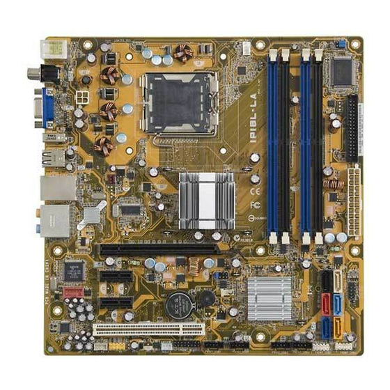
Motherboard layout 24.5cm (9.6in) CLEAR CMOS PS/2KBMS CLEAR PWD T: Mouse B: Keyboard CPU_FAN1 ASUS SPDIF1 F8000 LGA775 ATX12V I_1394 SYS_FAN1 LAN+USB ® Intel Bearlake GMCH ® Intel Top: 82566DC Subwoofer Speaker Out Center Top:Line In Rear Speaker Out Center:Line Out... -
Page 6: Central Processing Unit (Cpu)
Central Processing Unit (CPU) 2.1. Overview The motherboard comes with a surface mount LGA775 socket designed for the Intel Mainstream/Value FMB processor in the 775-land package. ® Installing the CPU To install a CPU: Locate the CPU socket on the motherboard. IPIBL-LA(Berkeley-GL8E) CPU Socket 775 Before installing the CPU, make sure that the socket box is facing towards you and the load lever is on your left. Press the load lever with your thumb (A), then move it to the left (B) until it is released from the retention tab. Retention tab PnP cap Load lever This side of the socket box should face you. - Page 7 Lift the load lever in the direction of the arrow to a 135º angle. Lift the load plate with your thumb and forefinger to a 100º angle (A), then push the PnP cap from the load plate window to remove (B). Load plate Alignment key Position the CPU over the socket, making sure that the gold triangle is on the bottom-left corner of the socket then fit the socket alignment key into the CPU notch CPU notch.
- Page 8 Close the load plate (A), then push the load lever (B) until it snaps into the retention tab. If installing a dual-core CPU, connect the chassis fan cable to the CHA_FAN1 connector to ensure system stability. Notes on Intel Hyper-Threading Technology ® • This motherboard supports Intel Mainstream/Value FMB processor in the ® 775-land package with Hyper-Threading Technology. • Hyper-Threading Technology is supported under Windows XP/2003 Server/ ® Vista and Linux 2.4.x (kernel) and later versions only. Under Linux, use the Hyper-Threading compiler to compile the code. If you are using any other operating systems, disable the Hyper-Threading Techonology item in the BIOS to ensure system stability and performance.
-
Page 9: System Memory
System memory The motherboard comes with four Double Data Rate 2 (DDR2) Dual Inline Memory Module (DIMM) sockets. A DDR2 module has the same physical dimensions as a DDR DIMM but has a 240-pin footprint compared to the 184-pin DDR DIMM. DDR2 DIMMs are notched differently to prevent installation on a DDR DIMM socket. The following figure illustrates the location of the DDR2 DIMM sockets. IPIBL-LA(Berkeley-GL8E) 240-pin DDR2 DIMM sockets Memory configurations You can install 512 MB, 1 GB, and 2 GB DDR2 SDRAM DIMMs into the DIMM sockets using the memory configurations in this section. • Installing DDR2 DIMMs other than the recommended configurations may cause memory sizing error or system boot failure. Use any of the recommended configurations on the next page. Install only identical (the same type and size) DDR2 DIMM pairs using the • recommended configurations. • Make sure that the memory frequency matches the CPU FSB (Front Side Bus). Refer to the Memory frequency/CPU FSB synchronization table on the next page. •... -
Page 10: Recommended Memory Configurations
Recommended memory configurations Sockets Mode DIMM1 DIMM2 DIMM3 DIMM4 Installed – – – – Installed – – Single-channel – – Installed – – – – Installed Installed – Installed – Dual-channel* – Installed – Installed Installed Installed Installed Installed * Use only identical DDR2 DIMM pairs. Memory frequency/CPU FSB synchronization CPU FSB DDR.DIMM.Type... -
Page 11: Installing A Ddr2 Dimm
Installing a DDR2.DIMM Unplug the power supply before adding or removing DIMMs or other system components. Failure to do so can cause severe damage to both the motherboard and the components. To install a DIMM: DDR2 DIMM notch Unlock a DIMM socket by pressing the retaining clips outward. Align a DIMM on the socket such that the notch on the DIMM matches the break on the socket. Firmly insert the DIMM into the socket until the retaining clips snap back in place and the DIMM is properly seated. -
Page 12: Expansion Slots
Expansion slots In the future, you may need to install expansion cards. The following sub-sections describe the slots and the expansion cards that they support. Make sure to unplug the power cord before adding or removing expansion cards. Failure to do so may cause you physical injury and damage motherboard components. Installing an expansion card To install an expansion card: Before installing the expansion card, read the documentation that came with it and make the necessary hardware settings for the card. Remove the system unit cover (if your motherboard is already installed in a chassis). Remove the bracket opposite the slot that you intend to use. Keep the screw for later use. Align the card connector with the slot and press firmly until the card is completely seated on the slot. Secure the card to the chassis with the screw you removed earlier. Replace the system cover. Configuring an expansion card After installing the expansion card, configure it by adjusting the software settings. -
Page 13: Interrupt Assignments
interrupt assignments Standard function System Timer Standard 101/102-key or Microsoft Natural PS/2 Keyboard ® System CMOS/Real Time Clock Microsoft® ACPI-Compliant System Intel® ICH9 Family SMBus Controller Microsoft® PS/2 Mouse Numeric Data Processor Intel® G33/G31 Express Chipset Family Intel® ICH9 Family USB Universal Host Controller Intel® ICH9 Family USB Universal Host Controller Intel® ICH9 Family USB Universal Host Controller Intel® ICH9 Family USB2 Enhanced Host Controller Intel® 82801HR/HH/HO SATA RAID Controller Intel ICH9 Family USB Universal Host Controller... -
Page 14: Pci Express X16 Slot
PCI Express x16 slot This motherboard supports PCI Express x16 graphic cards that comply with PCI Express specifications. The figure shows a graphics card installed on the PCI Express x16 slot. PCI Express x1 slot This motherboard supports PCI Express x1 network cards, SCSI cards and other cards that comply with the PCI Express specifications. The figure shows a network card installed on the PCI Express x1 slot. -
Page 15: Jumpers
Jumpers Clear RTC RAM (3-pin CLEAR CMOS) This jumper allows you to clear the Real Time Clock (RTC) RAM in CMOS. You can clear the CMOS memory of date, time, and system setup parameters by erasing the CMOS RTC RAM data. The onboard button cell battery powers the RAM data in CMOS, which include system setup information such as system passwords. To erase the RTC RAM: 1. Turn OFF the computer and unplug the power cord. 2. Move the jumper cap from pins 2-3 (Normal) to pins 1-2 (Clear CMOS) Keep the cap on pins 1-2 for about 5~10 seconds, then move the cap back to pins 2-3. 3. Plug the power cord and turn ON the computer. 4. Hold down the <Del> key during the boot process and enter BIOS setup to re-enter data. Except when clearing the RTC RAM, never remove the cap from the default position. Removing the cap will cause system boot failure! CLEAR CMOS Clear CMOS Normal (Default) IPIBL-LA(Berkeley-GL8E) Clear RTC RAM Clear password (3-pin CLEAR PWD) This jumper allows you to clear the password if you forgot your password. -
Page 16: Connectors
Connectors Rear panel connectors PS/2 mouse port (green). This port is for a PS/2 mouse. Coaxial S/PDIF Out port. This port connects an external audio output device via a coaxial S/PDIF cable. LAN (RJ-45) port. This port allows connection to a Local Area Network (LAN) through a network hub. Side Speaker Out port (gray). This port connects to the side speakers in an 8-channel audio configuration. Rear Speaker Out port (black). This port connects to the rear speakers on a 4-channel, 6-channel, or 8-channel audio configuration. Center/Subwoofer port (yellow orange). This port connects the center/ subwoofer speakers. Line In port (light blue). This port connects a tape, CD, DVD player or other audio sources. - Page 17 Audio 2, 4, 6, or 8-channel configuration Headset. Port 4-channels 6-channels 8-channels 2-channels Light Blue Line In Line In Line In Line In Lime Line Out Front Speaker Out Front Speaker Out Front Speaker Out Pink Mic In Mic In Mic In Mic In Orange – – Center/Subwoofer Center/Subwoofer Black –...
-
Page 18: Internal Connectors
6.2. Internal connectors This section describes and illustrates the internal connectors on the motherboard. Floppy disk drive connector (34-1 pin FLOPPY) This connector is for the provided floppy disk drive (FDD) signal cable. Insert one end of the cable to this connector, then connect the other end to the signal connector at the back of the floppy disk drive. Pin 5 on the connector is removed to prevent incorrect cable connection when using an FDD cable with a covered Pin 5. -
Page 19: Hdmi Connector
ATXPWR ATX12V +3 Volts Ground +12V DC +12V DC +12 Volts +5 Volts +12 Volts +5 Volts +5V Standby +5 Volts Power OK -5 Volts Ground Ground +5 Volts Ground Ground Ground +5 Volts PSON# Ground Ground +3 Volts -12 Volts IPIBL-LA(Berkeley-GL8E) +3 Volts +3 Volts... -
Page 20: Sata Connectors
Serial ATA connectors (7-pin SATA1, SATA2, SATA3, SATA4, SATA5, SATA6) These connectors are for the Serial ATA signal cables for Serial ATA hard disk drives. SATA1 SATA2 RSATA_RXN2 RSATA_TXP1 RSATA_TXN1 RSATA_RXP2 RSATA_RXP1 RSATA_TXN2 RSATA_TXP2 RSATA_RXN1 SATA3 SATA4 RSATA_RXN4 RSATA_TXP3 RSATA_TXN3 RSATA_RXP4 RSATA_RXP3 RSATA_TXN4 RSATA_RXN3 RSATA_TXP4 SATA5 SATA6 RSATA_TXP5 RSATA_RXN6 RSATA_RXP6 RSATA_TXN5 RSATA_RXP5 RSATA_TXN6 RSATA_TXP6 RSATA_RXN5 IPIBL-LA(Berkeley-GL8E) -
Page 21: Ieee 1394A Connector
IEEE 1394a connector (10-1 pin FRONT_1394) This connector is for an IEEE 1394a port. Connect the IEEE 1394a module cable to this connector, then install the module to a slot opening at the back of the system chassis. FRONT_1394 IPIBL-LA(Berkeley-GL8E) IEEE 1394 connector Never connect a USB cable to the IEEE 1394a connector. Doing so will damage the motherboard! USB connectors (10-1 pin FRONT_USB1, FRONT_USB2, FRONT_USB3) These connectors are for USB 2.0 ports. Connect the USB module cable to any of these connectors, then install the module to a slot opening at the back of the system chassis. These USB connectors comply with USB 2.0... - Page 22 CPU and System fan connectors (4-pin CPU_FAN1, 3-pin SYS_FAN1) These fan connectors support cooling fans of 350 mA~740 mA (8.88 W max.) or a total of 1 A~2.22 A (26.64 W max.) at +12 V. Connect the fan cables to the fan connectors on the motherboard, making sure that the black wire of each cable matches the ground pin of the connector. Do not forget to connect the fan cables to the fan connectors. Insufficient air flow inside the system may damage the motherboard components. These are not jumpers! DO not place jumper caps on the fan connectors. CPU_FAN1 Rotation +12V SYS_FAN1 Rotation +12V IPIBL-LA(Berkeley-GL8E) Fan connectors Internal audio connector (F_LINE_IN [White]) This connector allows you to receive stereo audio input from sound sources such as a CD-ROM, TV tuner, or MPEG card. IPIBL-LA(Berkeley-GL8E) Internal audio connector IPIBL-LA (Berkeley-GL8E)
-
Page 23: Digital/Front Panel Audio Connector
Digital audio connector (3-pin SPDIF2 [White]) This connector is for an additional Sony/Philips Digital Interface (S/PDIF) port(s). Connect the S/PDIF module cable to this connector, then install the module to a slot opening at the back of the system chassis. The S/PDIF module is purchased separately. SPDIF2 IPIBL-LA(Berkeley-GL8E) Digital audio connector 10. Front panel audio connector (10-1-pin F_AUDIO) This connector is for a chassis-mounted front panel headphone port. PIN1 IPIBL-LA(Berkeley-GL8E) Front panel audio connector IPIBL-LA (Berkeley-GL8E) -
Page 24: System Panel Connector
12. System panel connector (10-1 pin F_PANEL) This connector supports several chassis-mounted functions. PWR LED PWR BTN F_PANEL IPIBL-LA(Berkeley-GL8E) HD LED RESET System panel connector • System power LED (2-pin PLED) This 2-pin connector is for the system power LED. Connect the chassis power LED cable to this connector. The system power LED lights up when you turn on the system power, and blinks when the system is in sleep mode. Hard disk drive activity LED (2-pin HDLED) • This 2-pin connector is for the HDD Activity LED. Connect the HDD Activity LED cable to this connector. The IDE LED lights up or flashes when data is read from or written to the HDD. •...