
Related Manuals for MiLAN MIL-SM800P


Summary of Contents for MiLAN MIL-SM800P
- Page 1 Managed 8 & 9 Port Switches MIL-SM801P Eight 10/100BASE-TX Ethernet ports Plus One 100BASE-FX port MIL-SM801G Eight 10/100BASE-TX Ethernet ports Plus One 1000BASE-SX port MIL-SM800P Eight 10/100BASE-TX Ethernet ports USER GUIDE...
- Page 2 EN60950 (IEC950) - Product Safety Five-Year Limited Warranty MiLAN Technology warrants to the original consumer or purchaser that each of it's products, and all components thereof, will be free from defects in material and/or workmanship for a period of five years from the original factory shipment date. Any warranty hereunder is extended to the original consumer or purchaser and is not assignable.
-
Page 3: Table Of Contents
Console - Menu 4-1. Main Menu 4-2. Status and Counters 4-2-1. Port Status 4-2-2. Port Counters 4-2-3. System Information 4-3. Switch Static Configuration 4-3-1. Administration Configuration 4-3-1-1. Device Information 4-3-1-2. IP Configuration 4-3-1-3. Change Username 4-3-1-4. Change Password 4-3-2. Port / Trunk Configuration 4-3-3. - Page 4 4-4-2-2. Community Strings 4-4-2-3. Trap Managers 4-4-3. GVRP 4-4-4. LACP 4-4-4-1. Aggregator Setting 4-4-4-2. State Activity 4-4-4-3. LACP Status 4-5. Switch Reboot 4-6. Xmodem Upgrade 5. Web-Based Management Web Management 5-1. Web Management Home Overview 5-2. Port Status 5-3. Port Statistics 5-4.
-
Page 5: Introduction
Introduction The MIL-SM801P, MIL-SM801G and MIL-SM800P managed series of compact desktop switches are ideal solutions for network users. They provide wire-speed, Fast Ethernet switching providing high- performance data transfer. The switches feature a store-and-forward architecture with auto-learning of source addresses with an 8K-entry MAC address table. -
Page 6: Intelligent Management Features
VF-45 connector for MIL-SM801P series only One Fixed 1000Mbps Gigabit Ethernet port for MIL-SM801G series only One Console port on the rear for switch software configuration Half-duplex mode for back pressure and flow control for full- duplex Store-and-forward switching architecture... -
Page 7: Package Contents
User Guide Warranty Card If any item is missing or damaged, please contact your local dealer for service. Management Methods The MIL-SM801P, MIL-SM801G and MIL-SM800P switch series support the following management methods: Console and Telnet Management Web-based Management SNMP Network Management Console and Telnet Management Console Management is done through the RS-232 Console Port. -
Page 8: Hardware Description
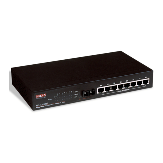
RJ-45 Ports (Auto MDI/MDIX): Eight 10/100 auto-sensing for 10BASE-T or 100BASE-TX connections. Figure 2-1. Front Panel for MIL-SM800P 100BASE-FX Fiber Port: There are 4 types of fiber connectors available for the MIL-SM801P. The distance for multi-mode fiber cabling can be up to 2 kilometers. -
Page 9: Led Indicators
LED Indicators Figure 2-4. LED Indicators There are three LED-Indicators (100M, LNK/ACT, FDX/COL) for each RJ-45 port. The following table provides descriptions of the LED statuses and meaning. They provide a real-time indication of systems operation status. LED Status Color Power Green Power On Green... -
Page 10: Rear Panel
Rear Panel The Console port and 3-pronged power plug are located at the Rear Panel of the MIL-SM801P, MIL-SM801G and MIL-SM800P switches as shown in Figure 2-5. The switches will work with AC in the range 100- 240V AC, 50-60Hz. -
Page 11: Attaching Rubber Feet
B. Remove adhesive backing from the rubber feet. C. Apply the rubber feet to each corner on the bottom of the switch. These footpads can protect the switch from shock and vibration. Figure 2-6. Attaching Rubber Feet to each corner on the bottom of the... -
Page 12: Network Application
Network Application Desktop Application The switch can be used as a standalone switch connecting personal computers, servers, or print servers directly connecting to form small workgroups. Figure 3-1. Desktop Application... -
Page 13: Segment Application
Segment Application For enterprise networks where large data broadcasts are constantly processed, this switch is suitable for individual department users to connect to the corporate backbone. Figure 3-2. Fiber port on MIL-SM801P switch extends the distance between workgroups... -
Page 14: Network Configuration
9 connector. From the main menu of the console program, the user has access to manage the functions of the switch. Figure 4-1. Connecting the switch to a terminal via RS-232 cable Use the supplied RS-232 cable to connect a terminal or PC to the console port. -
Page 15: Console - Menu
After the connection between switch and PC is finished, turn on the PC and run a terminal emulation program or HyperTerminal to match the following default characteristics of the console port: Baud Rate: 9600 bps Data Bits: 8 Parity: none... -
Page 16: Main Menu
Status and Counters: Shows the status of the switch. Switch Static Configuration: Menus to configure the switch. Protocol Related Configuration: Configures protocol features. Reboot switch: Restarts the system or resets switch to default configuration. Logout: Exits the menu line program. -
Page 17: Status And Counters
4-2. Status and Counters Press the Tab or Backspace key to choose action menu, and then press Enter key to select item. -
Page 18: Port Status
4-2-1. Port Status Type: Displays the port type of either 10/100TX or Fiber Enabled: A port that is enabled will be displayed as “Yes”. A port that is disabled will be displayed as “No”. Status: Displays the port’s link. “Down” the port has no link, and “Up” the port has a link with the remote device. -
Page 19: Port Counters
MAC Address: The unique hardware address. Firmware Version: Displays the switch’s firmware version. Hardware Version: Displays the switch’s hardware version. Default config value version: Rebooting the switch to defaults will load the version of software that is originally shipped with the switch. -
Page 20: Switch Static Configuration
4-3. Switch Static Configuration Press the Tab or Backspace key to choose action menu, and then press the Enter key to select item 4-3-1. Administration Configuration... -
Page 21: Device Information
4-3-1-1. Device Information Device Name: 10 characters can be used to give the switch a unique name in order to distinguish it on the network. After configuration this name will show at the top of each menu screen. Device Content: 32 characters can be used to describe devices attached. -
Page 22: Ip Configuration
4-3-1-2. IP Configuration This menu enables the user to change the default settings of the IP address, subnet mask and gateway. Rebooting the switch is necessary to have the configuration change take affect. Note: Always reboot the switch after finishing a new configuration. -
Page 23: Change Username
4-3-1-3. Change Username Use this page to change the User Name. 4-3-1-4. Change Password Use this screen to change the user management password. -
Page 24: Port / Trunk Configuration
4-3-2. Port / Trunk Configuration The menu provides per port configuration for speed and duplex as well as port trunking. Use the Space key to select the option preferred for each item. 1. Enabled: User can disable or enable the port. 2. -
Page 25: Port Mirroring Configuration
You can select a maximum of 8 ports to monitor in the switch. User can choose to monitor RX frames only or TX frames only or both RX and TX frames at the Action command line. -
Page 26: Vlan Configuration
4-3-4. VLAN Configuration All ports are automatically placed in VLAN 1, the default VLAN. To create new VLANs, use the Create a VLAN Group menu and add a VLAN. Make sure when you enter a VLAN name you do not leave spaces. For example VLAN2 is correct;... - Page 27 VLAN. One configuration that is common for port based VLANs is to have all the ports on the switch on separate VLANs except for the port that has the server connected. The port connected to the server belongs to all the VLANs.
- Page 28 Port Based VLANs To configure a new VLAN, select Edit and then use the tab key to select items you want to configure. The space bar allows you to select the different options. In the following configuration, ports 6, 7, and 8 are trunked. After adding a VLAN group, the configuration option Edit a VLAN Group will allow you to change the membership by adding or deleting ports.
- Page 29 IEEE802.1Q VLANs If IEEE802.1Q VLANs is selected, all the ports will belong to the default VLAN 1.
- Page 30 If more than one VLAN is necessary, the additional VLANs may be created. PVID (Port VID): Set the port VLAN ID that will be assigned to untagged traffic on a given port. This feature is useful for accommodating devices that you want to participate in the VLAN, but don’t support tagging.
-
Page 31: Create A Vlan Group
4-3-4-2. Create a VLAN Group To create a VLAN and add tagged /untagged member ports to it: 1. VLAN Name: Type a name for the new VLAN using 15 alphanumeric characters and no spaces. 2. VLAN ID: Type a VID (between 2~4094). The default is 1. 3. -
Page 32: Edit / Delete A Vlan Group
4-3-4-3. Edit / Delete a VLAN Group Use this menu to edit or delete a VLAN group. Choose <Edit> or <Delete>. Choose the VLAN to delete or edit by using the TAB key. VLAN 1, the default VLAN, can never be deleted. All other VLANs can be deleted using this menu. -
Page 33: Priority Configuration
These options represent the number of high priority packets sent before one low priority packet is sent. For example, 2 High : 1 Low means that the switch sends 2 high priority packets before sending 1 low priority packet. -
Page 34: Mac Address Configuration
11. In the Port Num field, enter the port number for the device. 12. The VLAN ID field is not available if the switch is configured for port based VLANs. If tag-based (802.1Q) VLANs are configured, the static addresses are associated with individual VLANs. - Page 35 Edit static MAC address 1. Press the <Edit> key to modify a static MAC address. 2. Use the tab key to choose the MAC address that you want to modify and then press enter. 3. Press the <Edit> key to modify all the items. 4.
-
Page 36: Misc. Configuration
4-3-7.Misc. Configuration 4-3-7-1.Port Security A port set in security mode will be “locked” and be without address learning. Only the incoming packets with the source MAC address already existing in the address table can be forwarded. With port security, users can disable a port from learning new MAC addresses. -
Page 37: Mac Age Interval
To configure a different MAC Age Interval, type the number of seconds that an inactive MAC address remains in the switch’s address table before it is deleted. Once the address is removed from the table, a device will have to send out broadcast packets to be relearned by the switch and have its address put in the table. -
Page 38: Broadcast Storm Filtering
4-3-7-3.Broadcast Storm Filtering Broadcast storm filtering is used to limit the amount of broadcast traffic on the network. An excessive amount of broadcast traffic can inhibit data packets from timely delivery. The valid threshold values are 5%, 10%, 15%, 20%, 25% and NO. If the broadcast traffic is greater than the configured value, broadcast packets will be dropped. -
Page 39: Max Bridge Transmit Delay Bound
Enable Delay Bound: If this parameter is enabled, the “Max bridge transmit delay bound” must also be configured. This item allows you to limit the queuing time of low priority packets in the switch. When the low priority packets exceed the “Max Delay Time” they will be transmitted. Press the Space key to enable or disable this function. -
Page 40: Protocol Related Configuration
4-4.Protocol Related Configuration 4-4-1.STP 4-4-1-1.STP Enable This page enables or disables the Spanning Tree function. Press the Space key to select Enabled or Disabled. -
Page 41: System Configuration
4-4-1-2.System Configuration The data on the left is for display only. The parameters on the right can be configured with new values. Priority: The value used to identify the root bridge. The bridge with the lowest value has the highest priority and is selected as the root. Enter a number 1 through 65535. -
Page 42: Stp Port Configuration
4-4-1-3.STP Port Configuration 1. PortState: Port spanning tree status. 2. PathCost: Specifies the path cost of the port that the switch uses to determine which ports are the forwarding ports. If you change the value, you need to restart the switch for the value change to take effect. - Page 43 4-4-2.SNMP Any Network Management station running the Simple Network Management Protocol (SNMP) can manage the switch provided that the Management Information Base (MIB) is installed. SNMP is a protocol that governs the transfer of information between management and agent. The switch supports SNMP V1.
-
Page 44: System Options
Press <Edit> to enter all items and then press <Save> to save the configured values. 1. System Name: Enter a name to be used to identify the switch. 2. System Contact: Enter the name of the contact person or organization. -
Page 45: Community Strings
4-4-2-2.Community Strings Community strings serve as passwords and can be entered as one of the following: 1. Read only: Enables requests accompanied by this string to display MIB- object information. 2. Read Write: Enables requests accompanied by this string to display MIB-object information and to set MIB objects. -
Page 46: Trap Managers
A trap manager is a management station that receives traps. System alerts are generated by the switch. If no trap manager is defined, no traps are issued. Create a trap manager by entering the IP address of the station and a community name. - Page 47 4-4-3.GVRP Use the GVRP Configuration screen to enable or disable GVRP (GARP VLAN Registration Protocol) support. Press the Space key to choose Enabled or Disabled. Actions-> <Edit>: Configures all items. When finished, pressing ESC returns to the action menu line. <Save>: Saves all configured values.
-
Page 48: Aggregator Setting
4-4-4-1.Aggregator Setting 1. Group: Displays the trunk group ID. NOTE: Before setting LACP support, you must first set the trunk group using the Port / Trunk Configuration screen. 2. LACP: Press the Space key to enable or disable the LACP (Link Aggregation Control Protocol) support. -
Page 49: State Activity
4-4-4-2.State Activity Active: The port automatically sends LACP protocol packets. Passive: The port does not automatically send LACP protocol packets and responds only if it receives LACP protocol packets from the opposite device. Actions-> <Edit>: Configures all items. When finished, pressing ESC returns to the action menu line. -
Page 50: Lacp Status
4-4-4-3.LACP Status When setting a trunking group, the relationship status information may be seen on the LACP Group Status screen. Actions-> <Quit>: Exits this page and returns to the previous menu. <Previous Page>: Returns to previous page to view. <Next page>: Go to next page to view. -
Page 51: Switch Reboot
4-5.Switch Reboot Default: Resets the switch to the factory defaults. The software version that the switch will be reset to can be found on the “System Information” menu under the main menu “Status and Counters”. Restart: Reboots the switch to enable items that have been configured. -
Page 52: Xmodem Upgrade
4-6. Xmodem Upgrade 1. First, modify the baud rate of the terminal to 57600bps. Then connect to the switch. 2. Press the X key to start upgrading for Xmodem. 3. Select “send file" under the "transfer" menu from menu bar. -
Page 53: Web-Based Management
Web-Based Management This section introduces the configuration and functions of the web-based management of MIL-SM801P, MIL-SM801G and MIL-SM800P switch series. The managed switch series provides an embedded HTML website residing in flash memory. This feature allows users to manage the switch from anywhere on the network through a standard web browser. -
Page 54: Web Management Home Overview
5-1. Web Management Home Overview 1. Home Page. -
Page 55: Port Status
5-2. Port Status 1. Port status State: Displays port status as off or on depending on user setting. “Unlink” means the port is offline or “off ”. Link Status: Down is “No Link”, Up is “Link”. Auto Negotiation: Indicates if the port is in auto negotiation mode. Speed status: Displays 100Mbps or 10Mbps speed. -
Page 56: Port Statistics
5-3. Port Statistics The following information provides a view of the current status of the unit. A single port counter as follows:... -
Page 57: Administrator
5-4-1. IP Address The IP Settings can be changed by filling in new values and clicking on the apply button. The switch must be reset for the new IP address to take effect. Default IP address is 192.168.1.77. -
Page 58: Miscellaneous Settings
Max bridge transit delay bound control: Limits the packets queuing time in the switch. If enabled, the packets that exceed the time limit in the queue will be dropped. The valid values are 1 sec, 2 sec, 4 sec and off (no limit). - Page 59 Weighted Round Robin: This option enables the user to choose a ratio of the number of high priority packets sent before one low priority packet is sent. For example, 2:1 (2 High : 1 Low) will have the switch send 2 high priority packets before sending 1 low priority packet.
- Page 60 IGMP Query Mode: Recognizes different queries from clients or servers to decide which Query will be the first priority. The three modes are: 1. Auto Mode: Chooses the switch that has the smallest IP address to be set for the IGMP Query mode.
- Page 61 4. IGMP Theory of Operation The following three topologies detail how IGMP Query works and to be configured within a network: 1. Auto mode needs to be enabled when the router’s IP address is smaller than other switches in the subnet. 2.
- Page 62 GVRP (GARP VLAN Registration Protocol) GVRP allows automatic VLAN configuration between the switch and nodes. A GVRP request can be sent using the VID of a VLAN defined on the switch when the switch is connected to a device with GVRP enabled. The switch...
-
Page 63: Console Port Information
5-4-3. Console Port Information The Windows HyperTerminal program can be used to link the switch with the console port. In order to change any of these parameters, you must be connected to the console port. Bits per seconds: 9600 Data bits: 8... -
Page 64: Port Controls
5-4-4. Port Controls The menu allows changing of port configurations. State: User can disable or enable this port. If disabled, there is no network communication through this port. Auto Negotiation: User can set port duplex and port speed to use auto negotiation. -
Page 65: Aggregator Setting
5-4-5-1. Aggregator Setting System Priority: A value used to identify the active LACP. The switch with the lowest value has the highest priority and is selected as the active LACP. 1. Group ID: To create a trunk across two or more ports, choose the "Group ID"... -
Page 66: Aggregator Information
5-4-5-2. Aggregator Information The LACP Aggregator relation information is displayed as shown. 5-4-5-3. State Activity Active (select): The active port automatically sends LACP protocol packets. Passive (no select): The passive port does not automatically send LACP protocol packets, but responds only if it receives LACP protocol packets from the other device. -
Page 67: Filter Database
IGMP has three fundamental types of message as follows: Message A message sent from the queryer (IGMP router or switch) asking for a Query response from each host belonging to the multicast group. A message sent by a host to the queryer to indicate that the host wants to be Report or is a member of a given group indicated in the report message. -
Page 68: Static Mac Address
5-4-6-2. Static MAC Address When a static MAC address is added, it remains in the switch's address table, regardless of whether or not the device is physically connected to the switch. This saves the switch from having to re-learn a device's MAC address when the device is disconnected or powered-off. -
Page 69: Port Security
5-4-6-3. Port Security A port in security mode will be “locked” with address learning blocked. Only the incoming packets with SMAC already existing in the address table can be forwarded normally. The user can disable the port from learning any new MAC addresses, then use the static MAC addresses screen to define a list of MAC addresses that can use the secure port. -
Page 70: Vlan Configuration
Layer 2 switch. However, all the network devices are still plugged into the same switch physically. The MIL-SM801P, MIL-SM801G, and MIL-SM800P switch series support port-based and protocol-based VLANs. In the default configuration, VLAN support is enabled and all ports on the switch belong to the default VLAN. -
Page 71: Basic
5-4-7-1. Basic VLAN Configuration By default, there are no VLANs set for the switch. In order to configure any of the different types of VLANs, VLANs need to be enabled in the switch using Settings/Advanced/Protocol Enable Settings/VLAN Operational Mode. The... - Page 72 2. Click Add. 3. Type a name for the new VLAN. 4. Type a VID (between 2-4094). The default is 1. 5. From the Available ports box, select ports to add to the switch and click Add. 6. Click Apply.
-
Page 73: Port Vid
Ingress Filtering Ingress filtering lets frames belonging to a specific VLAN be forwarded if the port belongs to that VLAN. The frames are dropped if not. The switch’s two ingress filtering rules are: Ingress Filtering Rule 1: Forwards only packets with VID matching this port’s configured VID. -
Page 74: Set Spanning Tree
Spanning-Tree Protocol can be enabled using web management’s switch setting advanced item, and selecting enable Spanning-Tree protocol. By default, spanning tree is disabled on the switch. - Page 75 The range is 0-255 and the default setting for all ports is 128. If you change the value, you must reboot the switch. Path Cost specifies the path cost of the port that the switch uses to determine which ports are the forwarding ports. The lowest number becomes the forwarding port.
-
Page 76: Port Mirroring
Mirror Ports: The ports you want to mirror. All source port traffic will be copied to a mirror port. You can select a maximum of 8 source ports in the switch. If you want to disable the function, you must select monitor port to none. -
Page 77: Snmp
5-4-10. SNMP SNMP is a protocol that governs the transfer of information between management and agent. The switch supports SNMP V1. Any Network Management station running the Simple Network Management Protocol (SNMP) can manage the switch provided that the Management Information Base (MIB) is installed. -
Page 78: Security Manager
A trap manager is a management station that receives traps. Traps are the system alerts generated by the switch. If no trap manager is defined, no traps are issued. Create a trap manager by entering the IP address of the station and a community string. -
Page 79: Tftp Update Firmware
5-4-12. TFTP Update Firmware The following menu options provide some system control functions to allow a user to update firmware and remotely boot the switch system: • Executing TFTP software • Copy firmware update version image.bin to TFTP software directory. -
Page 80: Tftp Backup Configuration
Use this screen to set the TFTP server IP address. You can save current EEPROM value from here, then go to the TFTP Restore Configuration screen to restore the EEPROM value. 5-4-14. Reset System Reset switch to default configuration. The default value is shown below: 5-4-15. Reboot Reboot the switch in software reset. -
Page 81: Technical Specifications
Technical Specifications This section provides the specifications of MIL-SM800P, MIL-SM801P, and MIL-SM801G switch series. Specifications IEEE 802.3 10BASE-T Ethernet, Standards Compliance IEEE 802.3u 100BASE-TX/FX Fast Ethernet ANSI/IEEE 802.3 Auto-negotiation CSMA/CD Protocol Max Forwarding 14,880 pps per Ethernet port, 148,800 pps per Fast Ethernet port... - Page 82 Operational Temp. 0ºC to 45ºC (32ºF to 113ºF) Operational 10% to 90% (Non-condensing) Humidity External Power 100-240V AC, 50-60Hz Power MIL-SM800P switch: 15 Watts (Max) Consumption MIL-SM801P/G switch series: 17 Watts (Max) FCC Class A, CE Mark Safety UL, cUL 1060 g...
-
Page 83: Improper Network Topologies
Data path loops will cause broadcast storms that will severely impact your network performance. Diagnostic LED Indicators The switch can be easily monitored through panel indicators to assist in identifying problems. If the power indicator does turn on when the power cord is plugged in, you may have a problem with power outlet or power cord. - Page 84 Cabling RJ-45 ports: Use unshielded twisted-pair (UTP) or shielded twisted-pair (STP) cable for RJ-45 connections: 100Ω Category 3, 4 or 5 cable for 10Mbps connections or 100Ω Category 5 cable for 100Mbps connections. Be sure that the length of any twisted-pair connection does not exceed 100 meters (328 feet).
- Page 88 90000405 Rev. A...
Need help?
Do you have a question about the MIL-SM800P and is the answer not in the manual?
Questions and answers