Advertisement
Quick Links
Download this manual
See also:
Applications
INSTALLATION INSTRUCTIONS FOR PART 99-3303
99-3303
KIT FEATURES
• DIN Head Unit Provision with
Driver Information Center (DIC)
• ISO DIN Head Unit Provision with
Driver Information Center (DIC)
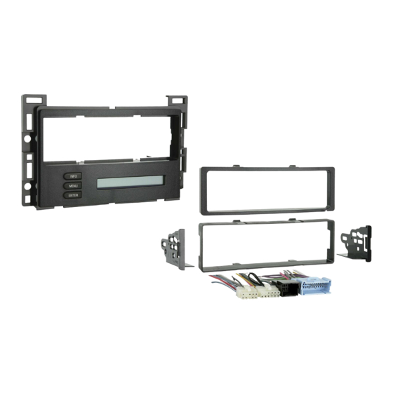
KIT COMPONENTS
A) Radio Housing • B) ISO Brackets • C) ISO Trim Plate • D) DIN Spacer • E) Wire Harness
A
Phillips Screwdriver • Socket Wrench • Flat Blade Screwdriver • Cutting Tool (Cobalt Only)
1-800-221-0932
© COPYRIGHT 2004-2009 METRA ELECTRONICS CORPORATION
APPLICATIONS
Chevrolet Cobalt 2005-2006
Chevrolet Malibu 2004-2007
Chevrolet Malibu Classic 2008
Pontiac G6 2005-2009
B
WIRING AND ANTENNA CONNECTIONS (Sold Separately)
Wiring Harness: Included
Antenne Adapter:
• 40-GM10 - GM antenna adapter 1988-up
TOOLS REQUIRED:
Wire Cutters • Wire Strippers
www.metraonline.com
D
E
C
Advertisement

Related Manuals for Metra Electronics 99-3303


Summary of Contents for Metra Electronics 99-3303
- Page 1 INSTALLATION INSTRUCTIONS FOR PART 99-3303 Chevrolet Cobalt 2005-2006 Chevrolet Malibu 2004-2007 Chevrolet Malibu Classic 2008 Pontiac G6 2005-2009 99-3303 KIT FEATURES • DIN Head Unit Provision with Driver Information Center (DIC) • ISO DIN Head Unit Provision with Driver Information Center (DIC) KIT COMPONENTS A) Radio Housing •...
- Page 2 • Operation of the 99-3303 ....... . . 8 •...
- Page 3 Remove (2) 7MM screws from bottom edge of panel below steering wheel. Unclip panel and let hang. It is not necessary to completely remove panel. (Figure C) Unclip and remove wood grain/painted trim pieces from above glove box. (Figure D) 99-3303...
- Page 4 99-3303 CHEVROLET MALIBU 2004-2007 CHEVROLET MALIBU CLASSIC 2008 Unclip and remove side panel from passenger side of dash with door open and remove (2) 7 MM screws from behind panel. (Figure E) Remove (2) 7 MM screws from bottom of...
- Page 5 Remove (4) screws from panel below steer- ing column and unclip and remove panel. (Figure B) Unclip and remove center panel surrounding radio and A/C controls. (Figure C) Remove (4) screws and extract radio from sub dash. (Figure D) 99-3303...
- Page 6 99-3303 CHEVROLET COBALT 2005-2006 Disconnect the negative battery terminal to prevent an accidental short circuit. Unclip and remove trim panel from above glove box. (Figure A) Unclip upper edge of panel below steering column and let hang. Not necessary to remove completely.
- Page 7 A snap-in DIN spacer has been provided for some applications where depth is an issue. Snap the spacer in the housing and slide the DIN cage into the assembly and secure by bending the metal locking tabs outward. (Figure C) 99-3303...
-
Page 8: Iso Din Head Unit Provisions
99-3303 ISO DIN HEAD UNIT PROVISIONS: Mount the ISO Brackets to the head unit with the screws supplied with the unit. (Figure A) Slide the head unit into the radio opening until the side clips engage. (Figure B) Snap the Trim plate into the Radio Housing. -
Page 9: Final Assembly
All colors may not be present on all leads due to manufacturer’s specifications. Plug the clear 10 way and 12 way connectors into the back of the 99-3303 housing. Connect the Lt. Blue 24 way connector to the factory 24 way harness. - Page 10 99-3303 OPERATION OF THE 99-3303 Settings and Adjustments mode There is a Settings and Adjustments mode available for the individualized adjustment of the contrast of the display, brightness of the display and backlighting, OnStar volume, and the button backlighting color.
- Page 11 99-3303...
- Page 12 INST993303 1-800-221-0932 www.metraonline.com Rev. 05-27-09 © COPYRIGHT 2004-2009 METRA ELECTRONICS CORPORATION INST99-3303...