Samsung SRN-1000 User Manual
Hide thumbs
Also See for SRN-1000:
- User manual (116 pages) ,
- Specifications (2 pages) ,
- Quick manual (8 pages)
Table of Contents
Advertisement
Quick Links
Advertisement
Table of Contents

Related Manuals for Samsung SRN-1000


Summary of Contents for Samsung SRN-1000
- Page 1 NETWORK VIDEO RECORDER User Manual SRN-1000...
-
Page 2: User Manual
Disclaimer Samsung Techwin makes the best to verify the integrity and correctness of the contents in this document, but no formal guarantee shall be provided. Use of this document and the subsequent results shall be entirely on the user’s own responsibility. Samsung Techwin reserves the right to change the contents of this document without prior notice. -
Page 3: Important Safety Instructions
overview imporTAnT SAfeTy inSTruCTionS Read these operating instructions carefully before using the unit. Follow all the safety instructions listed below. Keep these operating instructions handy for future reference. Read these instructions. Keep these instructions. Heed all warnings. Follow all instructions. Do not use this apparatus near water. -
Page 4: Before Start
• SAMSUNG retains the copyright on this manual. • This manual cannot be copied without SAMSUNG's prior written approval. • We are not liable for any or all losses to the product incurred by your use of non-standard product or violation of instructions mentioned in this manual. -
Page 5: System Shutdown
System Shutdown Turning off the power while the product is in operation, or undertaking improper actions may cause damage or malfunction to the hard drive or the product. For safe powering off, click <Shutdown> button on top right corner of the Web Viewer and confirm on prompted popup by clicking <oK>, and then disconnect the power cable. -
Page 6: Table Of Contents
overview ConTenTS overview Important Safety Instructions Before Start Contents Features Part Names and Functions (Front) Part Names and Functions (Rear) inSTALLATion Checking the installation environment Rack Installation HDD Addition ConneCTing wiTh oTher deviCe Connecting to an external device Connecting the Network Networking with IP Installer Port Range Forward (Port Mapping) Setup Connecting to the NVR From a Shared Local... - Page 7 SeArCh viewer Search Viewer menu SeTup Settings System Setup Setting the Device Setting the Recording Setting the Event Network Configuration Appendix Product Specification Product Overview Default Setting 100 Troubleshooting 103 Open Source License Notification on the Product English _7...
- Page 8 overview feATureS The product records video and audio from network cameras to a hard disk, and enables playback from the hard disk. It also provides remote monitoring environment for video and audio over the network using a remote computer. • VGA, 4CIF, record in a max of 2592x1944 (5M pixel) supported •...
-
Page 9: Package Contents
package Contents Please unwrap the product, and place the product on a flat place or in the place to be installed. Please check the following contents are included in addition to the main unit. ALARM NETWORK POWER Network Viewer Software / Power Cable User Manual and Installation Software CD User Manual or Quick Manual... -
Page 10: Part Names And Functions (Front)
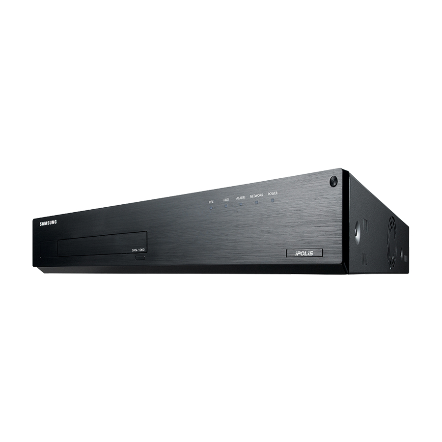
overview pArT nAmeS And funCTionS (fronT) ALARM NETWORK POWER Part Names Functions REC : Lights on when recording is in progress. HDD : Displays the normal access to HDD. LED turns on when accessing the hard disk. LED Indicator ALARM : Lights on when an event occurs. NETWORK : Displays both network connection and data transfer status. -
Page 11: Part Names And Functions (Rear)
pArT nAmeS And funCTionS (reAr) ALARM OUT ALARM RESET ALARM IN COM COM 1 2 3 4 5 6 7 8 9 10 11 12 13 14 15 16 Part Names Functions Port to connect a separate earth-grounding cable. Ground Add a separate earth-grounding cable to use your product safely. -
Page 12: Checking The Installation Environment
installation Please take note of the followings before using this product. • Do not use the product outdoor. • Do not spill water or liquid in the connection part of the product. • Do not impose the system to excessive shock or force. •... -
Page 13: Rack Installation
rACK inSTALLATion Install the Bracket-Rack as shown in the figure, and then fasten the screws on both sides (2 screws on each side). Fix the screws not to be loosened by vibrations. hdd AddiTion Make sure to unplug the power cord from the wall outlet to prevent possible electric shock, injury or product damage. Please consult your provider for further information on HDD installation since improper installation or settings may damage the product. - Page 14 installation 1. First, loosen the screws on both sides and remove Cover the cover. 2. Loosen the screws (x4) in the left/right and upper sides and remove the upper brackets. Upper Bracket Lower Bracket 3. Install HDDs (x4) on the lower bracket and fix them with screws.
- Page 15 5. When the installation of additional HDDs is done, insert the lower and upper brackets into the NVR and fix them with the provided screws. 6. When adding a HDD is completed, plug the power cable and connect the SATA cable (for transferring the HDD signal) to the connector of the main board.
-
Page 16: Connecting With Other Device
connecting with other device ConneCTing To An exTernAL deviCe eSATA HDD Alarm Power Sensors Unrated or improper power source may cause damage to the system. Ensure that you use only the rated power source before pressing the POWER button. Connecting external eSATA hdd External eSATA ports are provided on the rear panel by factory default. - Page 17 Connecting the Alarm input/output The Alarm In/Out port at the back is composed of the following. • ALARM IN 1 ~ 16 : Alarm Input Port • ALARM RESET : On receiving an Alarm Reset signal, the system cancels the current Alarm Input and resumes sensing.
-
Page 18: Connecting The Network
connecting with other device ConneCTing The neTworK For more information about network connection, refer to "Network Configuration". (Page 82) network connection via ethernet (10/100/1000BaseT) Switch Switch Network Camera Network Camera Windows Network Viewer network connection via router Switch Network xDSL or Cable xDSL or Cable Brodband router Camera... - Page 19 Connecting to network through pppoe Switch Phone(PPPoE) Line Network ADSL MODEM Camera NETWORK Network Camera Windows Network Viewer Switch Connecting the network camera Switch Network Camera Switch ex) IP : 192.168.2.10 Network Camera ex) IP : 192.168.2.20 Network Camera ex) IP : 192.168.1.20 Network Camera ex) IP : 192.168.1.10 You can connect the camera or network viewer to either [NETWORK1] or [NETWORK2] to your preference.
-
Page 20: Networking With Ip Installer
connecting with other device neTworKing wiTh ip inSTALLer Use provided IP Installer application program to search devices on the network and manually change the network settings of the searched device. Buttons used in ip installer Item Description Device Type Select a device type to search. Model name of the connected device. -
Page 21: Static Ip Setup
Exits the IP Installer program. For the IP installer, use only the installer version provided in the installation CD or use the latest one if available. You can download the latest version from the Samsung web site (www.samsungcctv.com). Static ip Setup manual network Setup Run <ip installer_vx.xx.exe>... - Page 22 connecting with other device if not using a Broadband router For setting <ip Address>, <Subnet mask>, and <gateway>, contact your network administrator. 4. In the <port> pane, provide necessary information. • HTTP Port : Used to access the NVR using the Internet browser, defaulted to 80. Use the spin button to change the HTTP Port value.
-
Page 23: Dynamic Ip Setup
3. Enter the password. The initial administrator ID is “admin” and the password should be set when logging in for the first time. Please change your password every three months to safely protect personal information and to prevent the damage of the information theft. -
Page 24: Port Range Forward (Port Mapping) Setup
connecting with other device porT rAnge forwArd (porT mApping) SeTup If you have installed a Broadband Router with a NVR connected, you must set the port range forwarding on the Broadband Router so that a remote PC can access the camera in it. manual port range forwarding 1. -
Page 25: Starting Web Viewer
starting web viewer whAT iS weB viewer? WebViewer is a software program with which the operator can access a remote NVR (Network Video Recorder) for real-time monitoring, PTZ control (if configured) or search. NETWORK Network Camera ALARM NETWORK POWER NETWORK Remote PC product features •... -
Page 26: Starting The System
starting web viewer STArTing The SySTem 1. Connect the power cable of the NVR to the wall outlet. 2. It turns on with a beep. 3. Open the web browser and enter the NVR’s IP address or URL in address field. 4. -
Page 27: Connecting Web Viewer
ConneCTing weB viewer 1. Open your web browser and type the IP address or URL of NVR into the URL address box. “192.168.1.200” is set to IP by default. Set to an available IP address in IP Installer or "Network > Connection Mode”. - Page 28 starting web viewer 5. When a program installation wizard window appears, press the [install] button to install the program. The version of the program installed may vary depending on the update version. 6. Open the Web Viewer after installing software, and log in again.
- Page 29 differences on using the web viewer By user permissions When running the Internet Explorer in Windows 7 or Vista, you can run the Web Viewer with administrator permission. You have different permission range depending on which permission you use between user and administrator.
- Page 30 starting web viewer To check the uAC operation 1. Select the Control Panel > User Account > Change User Account Control settings. 2. Set the UAC setting by adjusting the slide button in the left. To deactivate pop-up Blocking User may deactivate the Use pop-up blocker to use pop-up window which notifies corresponding status while using the Web Viewer.
- Page 31 Checking direct3d for normal operations of web viewer Direct3D must be properly operating to view Live Viewer’s video. 1. Click Windows Start button located on the left side of the screen and open the Search Programs and Files window. Enter “dxdiag” and press [enter] key. 2.
-
Page 32: Live Viewer
live viewer Live viewer You can check the video from camera registered in the NVR connected from a remote PC. Also, you can adjust the camera and check the network transfer status. Live viewer Screen m l k Menu Description Menu Selection Switches into corresponding menu screen by clicking each menu. - Page 33 Menu Description Capture Saves current video for selected channel in designated path. Print Prints current video image for selected channel through designated printer. Records the live video in AVI file format in designated path, and then stops recording. Save as AVI Recording status icon is displayed on screen during recording.
-
Page 34: Live Screen Configuration
live viewer Live SCreen ConfigurATion System Status You can check the status or operation of the NVR with the icons on the live screen. CAM 01 2013-01-01 09:54:36 Menu Description Displayed if there is a problem with the cooling fan. Displayed if the HDD needs a technical examination. - Page 35 Menu Description Camera Title / Display the camera title and channel number. Channel Current date The current date and time are displayed. and time This icon is displayed for a channel that a PTZ-featuring camera is connected to. Displays AUDIO ON/MUTE. Video Input Not displayed in video mode if deactivated.
- Page 36 live viewer registering the Camera You should register your camera and save corresponding settings before watching the video of registered camera in Live Viewer. To register the camera 1. Click the <Setup> menu. 2. Click the <device>-<Camera>-<registration> menu. 3. Click the <Auto> in Device Registration window. “Add Camera Automatically”...
- Page 37 Changing Split mode When clicking the Split Mode selection button, the screen is changed into the selected split mode. In the 36/64 segment screen, the OSD information is not displayed. To switch to Single screen mode Click < >. The monitor screen switches to the single screen of specified camera among displayed channels.
- Page 38 live viewer To switch to 16-split screen mode Click < >. The screen mode switches to 16-split screen mode which displays the channel group including currently specified camera. To switch to 36-split screen mode Click < >. The screen is switched to the 36-split mode, placing the channel group including the selected camera among the displayed channels at the top position.
-
Page 39: Switching The Split Mode
CH10 CH11 CH12 CH10 CH11 CH12 To switch to full screen mode CH13 CH14 CH15 CH16 CH13 CH14 CH15 CH16 Click < >. Current split screen appears in full screen. Press the [eSC] key to exit the full screen mode. CH19 CH19 CH10... - Page 40 live viewer To switch to previous/next channel Click < > or < > button. You can go to the previous/next screen image of connected device in current split mode. • Previous : Switches to the previous screen in reverse order. •...
- Page 41 To capture a screen 1. Click < > button. When a pop-up window appears, select the saving path for captured image. 2. Select the path and name the file. And then click the <Save> button. 3. Save current camera’s video image as .bmp, .jpg or .png file. If the viewer is running without the administrator’s permission in Windows Vista/7, you may not save the captured image as .bmp, .jpg or .png file.
-
Page 42: Controlling A Connected Network Camera
live viewer ConTroLLing A ConneCTed neTworK CAmerA Controlling pTZ If PTZ camera is connected, the < > icon appears on screen. When selecting corresponding camera channel, the PTZ tab is provided to allow you to control the PTZ. Item Description Direction Adjustment Adjusts the direction of a camera. - Page 43 To set a preset 1. Click < > button to display “preset” window. 2. Click < > to select a desired preset number. 3. Enter the name of preset. 4. Use direction keys to adjust the direction which camera aims 5.
- Page 44 live viewer Controlling oSd menu If connected network camera supports the OSD menu, press the < > to enter camera’s menu screen to change its settings. Item Description Direction Adjustment You can go to a desired menu. ENTER Selects a desired item. Camera Menu / Exit You can use / stop camera’s OSD menu settings.
-
Page 45: Record Status
Live Status Select <Live Status> from the live screen menu to display status and transfer information of connected camera to each channel. • Connection : Checks the connection status of registered camera. • IP : Checks camera’s IP address. • Codec : Checks camera’s tansfer profile. •... -
Page 46: Search Viewer
search viewer SeArCh viewer You can search and play the video record saved in NVR by accessing NVR remotely. Search viewer Screen m l k Item Description Menu Selection Switches to the corresponding menu screen by clicking each menu. Address, Name, Time Displays the IP, model name, time, etc. - Page 47 Item Description Displays and zooms in/out recorded video data. If overlapping data found, this function selects Overlapping Data one of them to play. Play Control Adjusts current video’s playback speed and played time position. Displays the corresponding color depending on recorded data type if you place your mouse Recording Color cursor on that area.
- Page 48 search viewer To adjust timeline If searched data are overlapping, you can select a desired data, move its playback time point, and zoom in/out the timeline. 1. Select the number of data to search if data is overlapping. It appears only when data are overlapped and assigns <0> to the most recent data. 2.
- Page 49 Item Description Stop Stops playing. When resuming playback, it is played from the recording start point. Pause Pauses playing. When resuming playback, it is played from the stopped point. Play Plays normally. Go to Last Moves to the recording end point on the corresponding timeline. English _49...
-
Page 50: Menu Setup
menu setup SeTTingS You can remotely configure the NVR on network. To configure the NVR settings, click <Setup>. Settings Screen h g f Item Description Menu Selection Click each menu to switch into corresponding menu screen. Parent Menu Configure the settings or select a parent item to change the existing settings. Sub-Menu Among the sub-menus of selected parent menu, select a desired item to set. -
Page 51: System Setup
SySTem SeTup You can setup Date/Time/Language, Permission, System Properties and Log. date/Time/Language Setting the date/Time/Language You can check and setup the current Date/Time and time related properties, as well as the language used for the interface on the screen. • Date: Set the date displayed on screen. •... - Page 52 menu setup Setting holiday You can set specific dates to Holidays according to your preferences. Holidays are applied to <recording Schedule> and <Alarm out Schedule> too. Ex : Select January 8th and check on <1/8> only to make every January 8th a holiday. Check both on <1/8> and <Jan 2nd Tue> to make every January 8th and 2nd Tuesday of January holidays.
-
Page 53: Setting The Group
• ID : Change the admin ID. • Password : Provide a new password. The initial administrator ID is “admin” and the password should be set when logging in for the first time. (Initial password of the Admin user is set to “4321”.) ID allows alphanumeric characters only. - Page 54 menu setup To set the group authority You can set the permissions of the group users to access the menu according to the channel. 1. Select a menu to which the group permission is assigned. The menu where the group permission is assigned will be displayed in the Live menu when a group user logs in.
- Page 55 Setting the users You can add a user and edit information of a registered user. To register a user 1. Select a user group. You must first register a group where the user will belong to so that user can be registered. (Page 53) 2.
- Page 56 menu setup Setting permissions You can set restricted access for all general users. Items with restrictions will require logging in for use. • Restricted Access : All menu items allowed for a user can be set with restricted access. - Checked ( ) : Restricted - Not checked ( ) : Accessible...
- Page 57 System manage You can confirm the version of the current system, update its version to recent one, or initialize the settings. Checking the System information You can check the current software version and MAC address before proceeding with the upgrade. It is not allowed to edit each setting value.
- Page 58 menu setup To upgrade the current software version 1. Prepare the software to upgrade. In case of server upgrade, NVR must be currently connected to the server in the network. When a new firmware is available in the network, the corresponding icon appears to notify the update. (Page 34) If connected through a proxy server, it may not be upgradable due to limited access.
-
Page 59: Log Information
• Export : Exports NVR settings to the connected storage device. • Import : Imports NVR settings from the storage device and applies to the NVR. - Check checkboxes of items to be excluded from importing. Only the other items than selected will be applied to the NVR. • Load Factory Default : Restore the factory default settings of NVR. -
Page 60: Checking The Event Log
menu setup Checking the event log You can search recorded events including alarms, camera events and video loss. It also shows the log and its timestamp. • Search Day : Click the Calendar button to select a desired search day. •... - Page 61 • Connection : Display the connection status. • Register : This is the default registration button for a network camera. It will be displayed <Auto> before registration, and will be changed to <delete> after registration. • Data rate : Displays the total amount of data received from the channel. •...
- Page 62 menu setup When you register a camera, the amount of data entered for a registration test will be automatically assigned to the max permitted bit rate. When you save a registered camera, general/event recording item in “Record Setup” will be set to <Full Frame>. Refer to “Record Setting”.
- Page 63 • Model : Select a camera model. - Samsung Network Camera/Encoder : Means the camera/encoder supports Samsung Techwin's SVNP protocol. When connecting a camera that does not appear in the camera list, select Samsung Netowrk Camera/Encoder. However, you must select the correct model name of the camera, if it's in the list. Some of obsolete camera models may not be supported.
- Page 64 • user model modification : When registering a new camera, it is named according to the device’s default if user set the model to <Samsung network Camera/encoder>. In case if automatic registration fails, user can change the model name of camera to be registered.
- Page 65 To edit camera profile When a camera is added for the first time, it is added as the default profile of H.264, MPEG4 and MJPEG in order temporarily. To change its profile, refer to "Setting the network camera’s recording profile" (Page 77) or "Live Streaming".
-
Page 66: Camera Setting
menu setup Camera Setting You can change the video settings of a registered network camera for each channel. • Select Camera : Select the camera channel to change the video transmission settings. • Profile : Displays video profile for connected camera settings. •... -
Page 67: Channel Setting
Channel Setting You can configure the video settings for each channel. • Video - <on/off> : You can turn ON/OFF the selected channel's camera. - <Covert> : Shows nothing but an empty screen while the recording continues. The channel whose video is set to <Covert> does not produce any sound. However, the channel’s sound is recorded if its Audio setting is set to <ON>, even the sound is not heard in Live mode. - Page 68 menu setup • No. : Shows the assigned number of the internal HDD. To see the detailed positioning of the HDD according to the number, refer to <HDD Map>. • Used/Total : Shows the used/total capacity of the storage device. • Usage : Sets the storage device's usage. You can select the eSATA HDD for extended storage If disconnected an extended eSATA HDD storage device while operating, the system may restart.
- Page 69 Connecting with iSCSi If you connect NVR with an iSCSI device, you can search, connect and disconnect the iSCSI device. • IQN (iSCSI Qualified Name) : The iSCSI name which is named to the iSCSI protocol format is displayed. • Used/Total : The used capacity and the total capacity of the iSCSI device are displayed. •...
- Page 70 menu setup registering an iSCSi device manually 1. On the iSCSI screen, click <manual Add>. 2. On the Manual Add screen, enter the IP address, the connecting port, the ID and the password, and click <oK>. deregistering iSCSi device 1. Select the iSCSI device to be selected from IQN. 2.
- Page 71 Setting the rAid mode If you activate the RAID (Redundant Array of Independent Disks) mode, you can safely recover data when the system HDD is damaged. RAID Level 5 of this NVR can work for a single HDD only in the RAID array to restore data in the event of a failure of that HDD.
- Page 72 menu setup Setting the rAid mode 1. Click the <use> or <Setup> button. 2. In the RAID setup window, select the Disk Array setup items and click the <oK> button. • Use : You can select whether or not to use the RAID mode. •...
- Page 73 recovering rAid Array 1. If the faulty/removed HDD number is displayed in <Status/management>, check the location of the HDD to be replaced on the HDD map. 2. On the Web Viewer, shut off the NVR system. 3. Remove the failed HDD from NVR and replace it with a new HDD. 4.
- Page 74 menu setup hdd Alarm Setting You can set alarm settings for HDD defects such as Check Alarm Output Port, Replace Alarm Output Port, iSCSI Alarm Output Port, and its duration. • Check Alarm Output Port : If HDD generates check alarm, the alarm signal will output to the specified alarm output port.
-
Page 75: Setting The Recording
SeTTing The reCording You can setup scheduled recording, event recording and other recording related settings. recording Schedule Make your reservation on a date and time to schedule the recording on specified time. • CH : Select the channel to configure scheduled recording. • All : The entire time range (Monday through Sunday including holidays, AM 0~ PM 23) will be reserved with the same recording schedule • Apply to All : If selected <Apply to All>, "Apply to All"... -
Page 76: Event Record Duration
menu setup event record duration You can set the beginning and ending point of a recording on an event. • Pre Event : The recording of an event will start at a pre-determined time prior to the actual occurrence of the event. If it is set to 5 seconds, the recording begins from 5 seconds before the event. - Page 77 • Full Frame : Shows the amount of received data for full frame recording. • Key Frame : Shows the amount of received data for key frame recording. • Bitrate Limit : Set the amount of data allowed for input for each channel. • Audio : Specify whether to record the sound received from the camera or not.
-
Page 78: Record Option
menu setup record option You can set the recording to stop or overwrite when the HDD is full. • Disk End Mode : Select a HDD repetitive recording type. - Overwrite : If the HDD is full, this will overwrite the existing data and keep recording. - Stop : If the HDD is full, this will stop recording automatically. -
Page 79: Setting The Event
SeTTing The evenT You can make the setup for record in case of sensor detection, camera event or video loss detection. Sensor detection You can set the sensor's operating condition and connected camera, as well as alarm output and its duration. Setting nvr Sensor detection • Sensor Operation : Sets the operation mode of sensors. - Page 80 menu setup Setting network Camera Sensor detection • Sensor Operation : Sets whether to operate the network camera sensor connected to each channel. • Cam : Select a channel to be connected to the sensor. If selected camera, "Cam preset setup" window appears. Select a channel and setup the preset.
-
Page 81: Video Loss Detection
video loss detection You can set the camera so that the camera can trigger the alarm if it is disconnected or the video is lost due to unstable network connection. • Video Loss State : Specify the use of video loss detection. • Alarm Out : Select an alarm output method. -
Page 82: Network Configuration
menu setup neTworK ConfigurATion It provides networked monitoring of Live screen from a remote place, and supports mail forwarding function with events. You can configure the network environment which enables such functions. interface You can set the network connection route and protocol. network1/network2 connection settings Sets the protocol and environment of the network. - Page 83 Setting the network Connection without router • Static - Internet connection : Static IP, PPPoE, leased line, and LAN environments allows connection between the NVR and remote user. - NVR Network Settings : Set the <interface> in <network> menu of the connected NVR to <Static>. Consult your network manager for IP, Gateway and Subnet Mask.
- Page 84 menu setup Setting the network Connection using router To avoid IP address conflict with the NVR's static IP, check followings : • Setting the nvr with a static ip - Internet connection : You can connect the NVR to a router which is connected to an PPPoE/Cable modem or a router in a Local Area Network (LAN) environment.
- Page 85 Setting port • Protocol Type : Select the protocol type between TCP and UDP. If you select UDP, the items of UDP Port and Unicast/Multicast will be active. If set it to TCP, the Device Port item will be active. • Device Port : Enter the connectable port number. Initially, <554> is set. - TCP : It has better stability and lower speed when compared to UDP, and recommended for internet environments.
- Page 86 menu setup ddnS You can set the DDNS site for a remote user's network connection. • DDNS Site : Specify the use of DDNS and select a site that you registered. • Host Name : Provide the host name that you registered with the DDNS site. • User Name : Provide the user ID that you registered with the DDNS Site.
-
Page 87: Ddns Setting
ddnS Setting DDNS is a short form of Dynamic Domain Naming System. DNS (Domain Name System) is a service that routes a domain name consisting of user friendly characters (ex : www.google.com) to an IP address consisting of numbers (64.233.189.104). DDNS (Dynamic DNS) is a service that registers a domain name and the floating IP address with the DDNS server so that the domain name can be routed to the IP address even if the IP is changed in a dynamic IP system. - Page 88 menu setup 802.1x When connecting to a network, you can select whether to use the 802.1x protocol and install corresponding certificate. 802.1x is an authentication system between the server and client to protect the data transferred in network from hacking, virus, leakage, etc. By using the 802.1x authentication, unauthenticated client is blocked to access, only authenticated users are allowed to communicate, and security is considerably improved.
- Page 89 Live Streaming You can configure the profile to transfer the live video of each channel via the network. • Profile : Select a network profile for the connected camera. • Codec : Show the codec information for the selected network profile. • Resolution : Display the resolution for the selected network profile. • Send Rate : Display the baud rate for the selected network profile.
-
Page 90: Event Setting
menu setup • Use Authentication : Check this if the SMTP server uses user authentication. The account input box will be activated. • ID : Enter a user to use authentication when connecting to the SMTP server. • Password : Enter the password of the SMTP server user. • Secure Transfer : Select one from <never>... -
Page 91: Dhcp Server
• Group : Specify the recipient group who receives the email event notification. - Add : Click the button to display the added group name input dialog. Enter the name, and click <oK> to add the group. - Delete : Deletes the selected group. - Rename : You can reset the recipient permission of an existing group. - Page 92 menu setup To set up the dhCp server 1. On the DHCP Server Setup screen, click <Setup>. 2. Select <run>in the <Status> field. 3. Enter the starting IP and end IP in the <ip range> field. 4. Enter <ip Lease Time>. 5.
-
Page 93: Appendix
Display Max. 64CH Input Channels 100Mbps Input Bandwidth Network Camera CIF ~ 5M Resolution Onvif(Samsung, Axis, Sony, Panasonic), Samsung Protocols Local Display Live 1 / 4 / 9 / 16 / 36 / 64 Sequence Performance Linux Operating System Embedded H.264, MPEG-4, MJPEG... - Page 94 RJ-45, Gigabit Ethernet x2 Interface TCP/IP, UDP/IP, RTP(UDP), RTP(TCP), RTSP, NTP, HTTP, DHCP, PPPoE, Protocol SMTP, ICMP, IGMP, ARP, DNS, DDNS, uPnP, ONVIF Samsung iPOLiS DDNS DDNS 64Mbps Transmission Bandwidth Search(3) / Live unicast(10) / Live multicast(20) Max Remote Users...
- Page 95 Item Details System System log, Up to 20,000 log records for each Event Log Log List Environmental Operating Temperature / +0°C to +40°C Humidity 20% ~ 85% Humidity Electrical 100 to 240 VAC ±10%; 50/60 Hz, 4~1.5A Power HDD 1 EA : 45W(MAX), 35W(Normal) Power Consumption RAID(HDD 8 EA) : 180W(MAX), 55W(Normal) Mechanical...
-
Page 96: Product Overview
appendix produCT overview unit : mm (inches) 96_ appendix... -
Page 97: Default Setting
defAuLT SeTTing To reset the system, move to “System management > Settings > Load factory default” and press the <default> button. This returns the factory default settings. The initial administrator ID is “admin” and the password should be set when logging in for the first time. (Initial password of the Admin user is set to “4321”.) Please change your password every three months to safely protect personal information and to prevent the damage of the information theft. - Page 98 appendix Category Details Factory Default Sensor Operation Camera No. Alarm Out None Duration 10 sec Sensor Detection Sensor Operation Camera No. Network Camera Alarm Out None Duration 10 sec Event Mode Camera Event Alarm Out None Duration 10 sec Video Loss State Video Loss Detection Alarm Out None...
- Page 99 Category Details Factory Default Network1 DDNS Site DDNS Network2 DDNS Site Filtering Type Deny IP Filtering IP Address 0.0.0.0 Prefix IEEE 802.1x EAPOL Version Network1 CA Certificates Not Available Clint Certificates Not Available Clint Private Key Not Available 802.1x IEEE 802.1x EAPOL Version Network2 CA Certificates...
-
Page 100: Troubleshooting
appendix TrouBLeShooTing Problem Action The system does not turn on and the indicator on the y Check if the power supply system is properly connected. front panel does not work at all. y Check the system for the input voltage from the power source. y If the problem persists even after you have taken the above actions, check the power supplier and replace it with a new one if neccessary. - Page 101 Problem Action Not all of multiple external HDDs that I have installed y It may take time to recognize multiple external HDDs. on the NVR are recognized by the NVR even if I Try again in a minute. If the problem persists and not all of the external HDDs configured the necessary settings properly.
- Page 102 appendix Problem Action Frame rate of the actual recording does not match y If multiple profiles were applied to one camera for video transmission, the that of configured to the camera. actual video stream can be serviced by the camera at a lower frame rate than specified.
-
Page 103: Open Source License Notification On The Product
Corresponding Source code from us for a period of three years after our last shipment of this product by sending email to help.cctv@samsung.com If you want to obtain the complete Corresponding Source code in the physical medium such as CD-ROM, the cost of physically performing source distribution might be charged. - Page 104 1. You may copy and distribute verbatim copies of the Program’s source source code, even though third parties are not compelled to copy the code as you receive it, in any medium, provided that you conspicuously source along with the object code. and appropriately publish on each copy an appropriate copyright notice 4.
- Page 105 no wArrAnTy signature of Ty Coon, 1 April 1989 Ty Coon, President of Vice This General Public License does not permit incorporating your program into 11. BECAUSE THE PROGRAM IS LICENSED FREE OF CHARGE, proprietary programs. If your program is a subroutine library, you may THERE IS NO WARRANTY FOR THE PROGRAM, TO THE EXTENT consider it more useful to permit linking proprietary applications with the library.
-
Page 106: Terms And Conditions
TermS And CondiTionS The Corresponding Source need not include anything that users can regenerate automatically from other parts of the Corresponding Source. 0. definitions. “This License” refers to version 3 of the GNU General Public License. The Corresponding Source for a work in source code form is that same work. - Page 107 d) If the work has interactive user interfaces, each must display “Installation Information” for a User Product means any methods, Appropriate Legal Notices; however, if the Program has interactive procedures, authorization keys, or other information required to install interfaces that do not display Appropriate Legal Notices, your and execute modified versions of a covered work in that User Product work need not make them do so.
- Page 108 All other non-permissive additional terms are considered “further You may not impose any further restrictions on the exercise of the rights restrictions” within the meaning of section 10. If the Program as you granted or affirmed under this License. For example, you may not received it, or any part of it, contains a notice stating that it is governed impose a license fee, royalty, or other charge for exercise of rights granted under this License, and you may not initiate litigation ( including a...
- Page 109 12. no Surrender of others' freedom. 17. interpretation of Sections 15 and 16. If conditions are imposed on you ( whether by court order, agreement or If the disclaimer of warranty and limitation of liability provided above otherwise ) that contradict the conditions of this License, they do not cannot be given local legal effect according to their terms, reviewing excuse you from the conditions of this License.
- Page 110 We call this license the “Lesser” General Public License because it does a) The modified work must itself be a software library. Less to protect the user’s freedom than the ordinary General Public b) You must cause the files modified to carry prominent notices License.
- Page 111 8. You may not copy, modify, sublicense, link with, or distribute the If such an object file uses only numerical parameters, data structure layouts and accessors, and small macros and small inline functions ( ten Library except as expressly provided under this License. Any attempt lines or less in length ) , then the use of the object file is unrestricted, otherwise to copy, modify, sublicense, link with, or distribute the Library is regardless of whether it is legally a derivative work.
-
Page 112: Openssl License
openSSL LiCenSe 14. If you wish to incorporate parts of the Library into other free programs whose distribution conditions are incompatible with these, Copyright ( c ) 1998-2006 The OpenSSL Project. All rights reserved. write to the author to ask for permission. For software which is copyrighted by the Free Software Foundation, write to the Free Software Redistribution and use in source and binary forms, with or without Foundation;... - Page 113 4. If you include any Windows specific code ( or a derivative thereof ) from IN NO EVENT SHALL THE COPYRIGHT OWNER OR CONTRIBUTORS the apps directory ( application code ) you must include an BE LIABLE FOR ANY DIRECT, INDIRECT, INCIDENTAL, SPECIAL, EXEMPLARY, OR CONSEQUENTIAL DAMAGES ( INCLUDING, BUT acknowledgement: “This product includes software written by Tim Hudson ( tjh@cryptsoft.com ) ”...
- Page 114 The copyright notices in the Software and this entire statement, including For more information on the PHP Group and the PHP project, the above license grant, this restriction and the following disclaimer, must please see <http://www.php.net>. be included in all copies of the Software, in whole or in part, and all PHP includes the Zend Engine, freely available at derivative works of the Software, unless such copies or derivative works <http://www.zend.com>.
- Page 121 Samsung Techwin cares for the environment at all product manufacturing stages, and is taking measures to provide customers with more environmentally friendly products. The Eco mark represents Samsung Techwin’s devotion to creating environmentally friendly products, and indicates that the product satisfies the EU RoHS Directive.
- Page 122 SAMSUNG TECHWIN AMERICA Inc. SAMSUNG TECHWIN EUROPE LTD. 100 Challenger Rd. Suite 700 Ridgefield Park, NJ 07660 Samsung House, 1000 Hillswood Drive, Hillswood Business Park Toll Free : +1-877-213-1222 Direct : +1-201-325-6920 Chertsey, Surrey, UNITED KINGDOM KT16 OPS Fax : +1-201-373-0124 TEL : +44-1932-45-5300 FAX : +44-1932-45-5325 www.samsungcctvusa.com...