
Related Manuals for Mercedes-Benz 2008 CLS 550


Summary of Contents for Mercedes-Benz 2008 CLS 550
- Page 1 Sommer\ Corporate\ Media\ AG Bild in der Größe 215x70 mm einfügen Operator’s Manual CLS-Class Order No. 6515 1429 13 Part No. 219 584 98 81 USA Edition A 2008...
- Page 2 CLS 550 CLS 63 AMG...
- Page 3 Your Mercedes-Benz represents the ef- forts of many skilled engineers and crafts- men. To help assure your driving pleasure, and also the safety of you and your passen-...
-
Page 4: Table Of Contents
Operator’s Manual ... 10 Service and warranty information .. 10 Important notice for California retail buyers and lessees of Mercedes-Benz automobiles ... 11 Maintenance ... 12 Roadside Assistance ... 12 Change of address or ownership... 12 Operating your vehicle outside the USA or Canada... - Page 5 Contents Safety and Security ... 63 Occupant safety... 64 Air bags ... 66 Occupant Classification System... 71 Seat belts ... 76 Preventive occupant safety ® (PRE-SAFE ) ... 80 Active head restraints ... 81 Children in the vehicle... 82 Blocking of rear door window operation ...
- Page 6 Menus ... 142 Standard display menu ... 145 AMG menu ... 145 AUDIO menu ... 148 NAV* menu... 150 Distronic* menu... 151 Vehicle status message memory menu ... 151 Settings menu... 152 Trip computer menu... 164 TEL* menu ... 166 Automatic transmission...
- Page 7 Contents Useful features ... 243 Storage compartments... 243 Cup holders... 246 Ashtrays ... 248 Cigarette lighter ... 249 Power outlets ... 250 Heated steering wheel (Canada only) ... 251 Floormats ... 252 Telephone*... 253 Tele Aid ... 256 Garage door opener ... 262 Operation ...
- Page 8 Maximum tire inflation pressure .. 320 Uniform Tire Quality Grading Standards (U.S. vehicles) ... 321 Tire ply material ... 323 Tire and loading terminology... 323 Rotating tires ... 326 Winter driving ... 328 Winter tires ... 328 Block heater* (Canada only) ... 329 Snow chains...
- Page 9 Contents Technical data... 431 Parts service ... 432 Warranty coverage... 433 Loss of Service and Warranty Information Booklet... 433 Identification labels... 434 Layout of poly-V-belt drive ... 436 CLS 550 ... 436 CLS 63 AMG... 436 Engine... 437 Rims and tires... 438 Same size tires...
-
Page 10: Introduction
Product information Please observe the following in your own best interest: We recommend using Genuine Mercedes-Benz Parts as well as conversion parts and accessories explicitly approved by us for your vehicle model. We have tested these parts to determine their reliability, safety and special suitabili- ty for Mercedes-Benz vehicles. -
Page 11: Operator's Manual
Therefore, you may find explanations for optional equipment not installed in your vehicle. If you have any questions about the operation of any equipment, any authorized Mercedes-Benz Center will be glad to demonstrate the proper proce- dures. We continuously strive to improve our... -
Page 12: Mercedes-Benz Automobiles
Under California law you may be entitled to a replacement of your vehicle or a refund of the purchase price or lease price, if Mercedes-Benz USA, LLC and/or its au- thorized repair or service facilities fail to fix one or more substantial defects or mal-... -
Page 13: Maintenance
Calls to the toll-free Roadside Assistance number 1-800-FOR-MERCedes (in the USA) 1-800-387-0100 (in Canada) will be answered by Mercedes-Benz Customer Assistance Representatives 24 hours a day, 365 days a year. For additional information refer to the... -
Page 14: The Usa Or Canada
Certain Mercedes-Benz models are avail- able for delivery in Europe under our Euro- pean Delivery Program. For details, consult an authorized Mercedes-Benz Center or... -
Page 15: Where To Find It
Here you will find all the information you need for your first drive. You should read this section first if this is your first Mercedes-Benz vehicle or if you are rent- ing or borrowing this vehicle. Safety and Security Here you will find descriptions of the safety and security features of your vehicle. -
Page 16: Symbols
Symbols Trademarks: ® ® and PRE-SAFE are registered trademarks of DaimlerChrysler. ® HomeLink is a registered trademark of Prince, a Johnson Controls Company. The following symbols are found in this Operator’s Manual: Optional equipment is identified with an asterisk. Since standard equipment varies between models, the descriptions and illustrations in this manual may differ slightly from... -
Page 17: Operating Safety
Electronic malfunctions could seri- ously impair the operating safety of your ve- hicle. See your authorized Mercedes-Benz Center for repairs or modifications to electronic components. Other improper work or modifications on the vehicle could also have a negative impact on the operating safety of the vehicle. -
Page 18: Problems With Your Vehicle
If you should experience a problem with your vehicle, particularly one that you believe may affect its safe operation, we urge you to immediately contact an authorized Mercedes-Benz Center to have the problem diagnosed and corrected if required. If the matter is... -
Page 19: Reporting Safety Defects
If you believe that your vehicle has a defect which could cause a crash or could cause injury or death, you should immediately inform the National Highway Traffic Safety Administration (NHTSA) in addition to notifying Mercedes-Benz USA, LLC. If NHTSA receives similar complaints, it may open an investigation, and if it finds that a safety defect exists in a group of vehicles, it may order a recall and remedy campaign. -
Page 20: Vehicle Data Recording
Vehicle data recording Information regarding electronic recording devices (Including notice pursuant to California Code § 9951) Please note that your vehicle is equipped with devices that can record vehicle systems data and, if equipped with the Tele Aid system, may transmit some data in certain accidents. This information helps, for example, to diagnose vehicle systems after a collision and to continuously improve vehicle safety. -
Page 22: At A Glance
At a glance Exterior view Cockpit Instrument cluster Multifunction steering wheel Center console Overhead control panel Storage compartments Door control panel... -
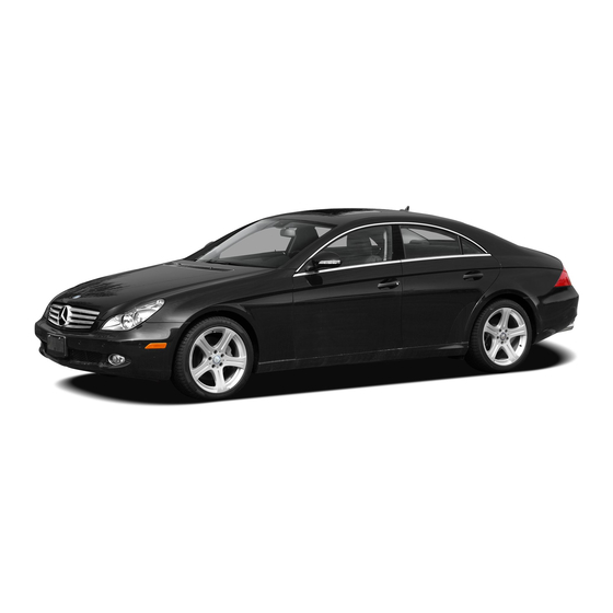
Page 23: Exterior View
At a glance Exterior view... - Page 24 Item Page 1 Trunk Unlocking Opening and closing Spare wheel Vehicle tool kit 2 Rear lamps 3 Rear window, defrosting 4 Fuel filler flap Fuel requirements 5 Doors Locking and unlocking Opening and closing Item Page 6 Towing eye bolt Installing towing eye bolt 7 Rims and tires Checking tire inflation...
-
Page 25: Cockpit
At a glance Cockpit... - Page 26 Item Page 1 Combination switch Turn signals Windshield wipers High beam 2 Steering wheel gearshift control* 3 Cruise control lever Cruise control Distronic* 4 Multifunction steering wheel 5 Instrument cluster 6 Horn Item Page 7 Lever for Voice Control Sys- tem*, see separate operating instructions 8 Front Parktronic* warning...
-
Page 27: Instrument Cluster
At a glance Instrument cluster... - Page 28 Item Page 1 L Left turn signal indicator lamp 2 v ESP ® warning lamp 3 Speedometer 4 Multifunction display 5 l Distance warning lamp Vehicles without Distronic*: Warning lamp without func- tion. It illuminates with the ignition on. It should go out when the engine is running.
-
Page 29: Important Notice For California Multifunction Steering Wheel
At a glance Multifunction steering wheel Item Page 1 Multifunction display in speedometer Operating control system 2 Selecting the submenu or setting the volume: Press button æ up/to increase ç down/to decrease 3 Telephone*: Press button s to take a call to dial to redial t to end a call... -
Page 30: Retail Buyers And Lessees Of Center Console
Center console Upper part Item Page 1 4-zone automatic climate control 2 COMAND system, see sepa- rate operating instructions 3 Seat heating*, front passen- ger side Seat ventilation*, front pas- senger side 4 Electronic Stability Program ® (ESP ) control switch 5 Central locking switch At a glance Center console... -
Page 31: Lower Part
At a glance Center console Lower part Item Page 1 Ashtray 2 KEYLESS-GO* start/stop button 3 Gear selector lever for automatic transmission 4 Parking assist (Parktronic system)* deactivation switch 5 Adaptive Damping System (ADS) switch Item Page 6 Vehicle level control button 7 Thumbwheel for setting dis- tance in Distronic* 8 Distance warning function*... -
Page 32: Overhead Control Panel
Overhead control panel Item Page 1 Rear interior lighting on/off 2 Automatic interior lighting 3 Front interior lighting on/off 4 Right front reading lamp on/off 5 Power tilt/sliding sunroof switch 6 Tele Aid (emergency call system) button 7 Rear view mirror 8 Front reading lamps At a glance Overhead control panel... -
Page 33: Storage Compartments
At a glance Storage compartments... - Page 34 Item Page 1 Glove box 2 Front passenger seat storage compartment with first aid kit 3 Door pocket 4 Ashtray 5 Ruffled storage bag 6 Door pocket 7 Side storage pocket in trunk 8 Luggage box under the trunk floor 9 Door pocket a Ruffled storage bag b Ashtray...
-
Page 35: Operating Your Vehicle Outside Door Control Panel
At a glance Door control panel Item Page 1 Inside door handle 2 Seat adjustment 3 Memory function (for stor- ing seat, exterior mirror and steering wheel settings) 4 Exterior rear view mirror ad- justment 5 Switches for opening/clos- ing front and rear side win- dows, rear window override switch 6 Remote trunk release... -
Page 36: Getting Started
Getting started Unlocking Adjusting Driving Parking and locking... -
Page 37: Unlocking
Getting started Unlocking The “Getting started” section provides an overview of the vehicle’s most basic func- tions. First-time Mercedes-Benz owners should pay special attention to the infor- mation given here. If you are already familiar with the basic functions described here, the “Controls in detail”... -
Page 38: Unlocking With Keyless-Go
Opening a door causes the window on that door to open slightly. They will return to the up position when the door is closed. The side windows will not open or close if the battery is discharged or the windows are cov- ered with ice. -
Page 39: Starter Switch Positions
Getting started Unlocking Starter switch positions Warning! When leaving the vehicle, always remove the SmartKey or SmartKey with KEYLESS-GO* from the starter switch, take it with you, and lock the vehicle. Do not leave children unat- tended in the vehicle, or with access to an unlocked vehicle. - Page 40 The SmartKey can only be removed from the starter switch with the gear selector lever in position P. If the SmartKey is left in starter switch posi- tion 0 for an extended period of time, it can no longer be turned in the switch. In this case, the steering is locked.
- Page 41 Getting started Unlocking Position 0 Before you press the KEYLESS-GO start/ stop button, the vehicle’s on-board elec- tronics have status 0 (as with SmartKey re- moved). Position 1 Press KEYLESS-GO start/stop button once. This supplies power for some electrical consumers. If you now press the KEYLESS-GO start/stop button once again, the ignition (position 2) is...
-
Page 42: Adjusting
Adjusting Warning! All seat, head restraint, steering wheel, and rear view mirror adjustments, as well as fas- tening of seat belts, must be done before the vehicle is put into motion. Seats Warning! Do not adjust the driver’s seat while driving. Adjusting the seat while driving could cause the driver to lose control of the vehicle. - Page 43 Getting started Adjusting Warning! When leaving the vehicle, always remove the SmartKey or the SmartKey with KEYLESS-GO* from the starter switch, take it with you, and lock the vehicle. Even with the SmartKey or the SmartKey with KEYLESS-GO* removed from the starter switch or the SmartKey with KEYLESS-GO* removed from the vehicle, the power seats can be operated when the...
- Page 44 Seat fore and aft adjustment Press the switch forward or backward in direction of arrow 1. Depending on the set height of the head re- straint, the seat fore and aft position is automat- ically pre-set. Backrest tilt Press the switch forward or backward in direction of arrow 2.
-
Page 45: Steering Wheel
Getting started Adjusting Comfort head restraint* adjusting 1 Head restraint side adjustment 2 Head restraint fore and aft adjustment Warning! When folding back the side cushions, never reach between the side cushion and the mounting post. You could otherwise be trapped. - Page 46 Steering wheel adjustment The stalk for steering wheel adjustment is located on the steering column (lower left). 1 Adjusting steering column, in or out 2 Adjusting steering column, up or down Adjusting steering column in or out Move stalk in direction of arrows 1 until a comfortable steering wheel posi- tion is reached with your arms slightly bent at the elbow.
- Page 47 Getting started Adjusting With the easy-entry/exit feature activated, the steering wheel will return to its last set position when you close the driver’s door with the ignition switched on insert the SmartKey into the starter switch or press the KEYLESS-GO* start/stop button ( page 39) once with the driver’s door closed The last set steering wheel position is stored...
-
Page 48: Mirrors
Mirrors Adjust the interior and exterior rear view mirrors before driving so that you have a good view of the road and traffic condi- tions. Interior rear view mirror Manually adjust the interior rear view mirror. For more information, see “Rear view mir- rors”... -
Page 49: Driving
Getting started Driving Warning! Make sure that absolutely no objects are ob- structing the pedals range of movement. Keep the driver’s footwell clear of all obsta- cles. If there are any floormats or carpets in the footwell, make sure that the pedals still have sufficient clearance. - Page 50 Warning! Never ride in a moving vehicle with the seat backrest in an excessively reclined position as this can be dangerous. You could slide under the seat belt in a collision. If you slide under it, the belt would apply force at the abdomen or neck.
- Page 51 Do not bleach or dye seat belts as this may severely weaken them. In a crash they may not be able to provide adequate protection. Damaged seat belts or belts that were highly stressed in an accident must be replaced. Contact an authorized Mercedes-Benz Center.
-
Page 52: Starting The Engine
Starting the engine Warning! Inhalation of exhaust gas is hazardous to your health. All exhaust gas contains carbon monoxide (CO), and inhaling it can cause un- consciousness and possible death. Do not run the engine in confined areas (such as a garage) which are not properly ventilated. - Page 53 Getting started Driving Starting with KEYLESS-GO* Warning! As long as the SmartKey with KEYLESS-GO is in your vehicle, the vehicle can be started. Therefore, never leave children unattended in the vehicle, as they could otherwise acci- dentally start the engine. When leaving the vehicle, always take the SmartKey with KEYLESS-GO with you and lock the vehicle.
-
Page 54: Parking Brake
If the engine does not start after several starting attempts, there could be a mal- function in the engine electronics or in the fuel supply system. Contact an authorized Mercedes-Benz Center or call Roadside Assistance. Parking brake 1 Release handle... - Page 55 Getting started Driving Once the vehicle is in motion, the automatic central locking system engages and the locking knobs drop down. The automatic door lock feature can be deacti- vated ( page 163). You can open a locked door from the inside. Open door only when conditions are safe to do After a cold start, the automatic transmis- sion engages at a higher revolution.
-
Page 56: Switching On Headlamps
Switching on headlamps Low beam headlamps Exterior lamp switch 1 Off 2 Low beam headlamps on Turn the exterior lamp switch to position B. The low beam headlamps, the green in- dicator lamp C in the exterior lamp switch and the low beam headlamp in- dicator lamp B in the instrument cluster come on. -
Page 57: Windshield Wipers
U or V, set the combination switch to the next high- est wiper speed have the windshield wipers checked at the nearest authorized Mercedes-Benz Center Switching on windshield wipers Turn the combination switch to the de- sired position depending on the inten- sity of the rain. - Page 58 Intermittent wiping Only switch on intermittent wiping under wet weather conditions or in the presence of precipitation. Do not leave windshield wipers in intermittent setting when the vehicle is taken to an automatic car wash or during windshield cleaning. Windshield wipers will operate in the presence of water sprayed on the windshield, and windshield wipers may be damaged as a re- sult.
-
Page 59: Problems While Driving
Unburned gasoline may have entered the catalytic converter and damaged it. Give very little gas. Have the problem repaired by an authorized Mercedes-Benz Center as soon as possible. The coolant temperature is above 248°F (120°C) The coolant is too hot and is no longer cooling the engine. -
Page 60: Parking And Locking
Parking and locking You have now completed your first drive. You have properly stopped and parked your vehicle. End your drive as follows. Warning! With the engine not running, there is no power assistance for the brake and steering systems. In this case, it is important to keep in mind that a considerably higher degree of effort is necessary to brake and steer the ve- hicle. -
Page 61: Switching Off Headlamps
Getting started Parking and locking 1 Release handle 2 Parking brake pedal Step firmly on parking brake pedal 2. When the engine is running, the warn- ing lamp ; (USA only) or 3 (Canada only) in the instrument cluster will be illuminated. Warning! When leaving the vehicle, always remove the SmartKey or SmartKey with KEYLESS-GO*... -
Page 62: Releasing Seat Belts
Such damage is not covered by the Mercedes-Benz Limited Warranty. Damaged seat belts must be replaced. Contact an authorized Mercedes-Benz Center. Locking Warning! To prevent possible personal injury, always keep hands and fingers away from the door openings when closing the doors. - Page 63 Getting started Parking and locking If you hear a warning signal you have forgot- ten to switch off the low beam headlamps or the parking lamps before opening the driver’s door. In addition the message Switch Off Lights appears in the multifunction display. Switch off the low beam headlamps or the park- ing lamps.
-
Page 64: Safety And Security
Safety and Security Occupant safety Panic alarm Driving safety systems Anti-theft systems... -
Page 65: Occupant Safety
Safety and Security Occupant safety In this section you will learn the most im- portant facts about the restraint systems of the vehicle. The restraint systems are Seat belts ( page 76) Child restraints ( page 82) Lower Anchors and Tethers for CHildren (LATCH) ( page 86) Additional protection is provided by Supplemental Restraint System (SRS) - Page 66 Mercedes-Benz Center. Safety and Security Occupant safety If it is necessary to modify an air bag system to accommodate a person with disabilities, contact your local authorized Mercedes-Benz Center or call our Customer Assistance Center at 1-800-FOR-MERCedes (1-800-367-6372) for details.
-
Page 67: Air Bags
If you have any prob- lems, please contact your authorized Mercedes-Benz Center. Do not lean with your head or chest close to the steering wheel or dash- board. - Page 68 Mercedes-Benz Center at an additional cost. Please contact your local authorized Mercedes-Benz Center or call our Customer Assistance Center at 1-800-FOR-MERCedes (1-800-367-6372) for details.
- Page 69 Use only seat belts installed or supplied by an au- thorized Mercedes-Benz Center. Air bags and Emergency Tensioning Devices (ETDs) contain Perchlorate ma- terial, which may require special han- dling and regard for the environment.
- Page 70 Warning! Only use seat covers which have been test- ed and approved by Mercedes-Benz for your vehicle model. Using other seat covers may interfere with or prevent the deployment of the side impact air bags. Contact your au- thorized Mercedes-Benz Center for availabil- ity.
- Page 71 Safety and Security Occupant safety The front air bags in this vehicle have been designed to inflate in two stages. This allows the air bag to have different rates of inflation that are based on the rate of vehicle deceleration as as- sessed by the air bag control unit.
-
Page 72: Occupant Classification System
If your seat, including your trim cover and cushion needs to be serviced in any way, take the vehicle to an authorized Mercedes-Benz Center. Only seat accessories approved by Mercedes-Benz may be used. - Page 73 Safety and Security Occupant safety Warning! If the 75 indicator lamp illumi- nates when an adult or someone larger than a small individual is in the front passenger seat, have the front passenger re-position himself or herself in the seat until the 75 indicator lamp goes out, or check whether objects are caught under or around the seat.
- Page 74 If the 75 indicator lamp is illu- minated, the front passenger front air bag is deactivated and will not be deployed. If the 75 indicator lamp is not illuminated, the front passenger front air bag is activated and will be deployed: in the event of certain frontal impacts if impact exceeds a preset deployment threshold...
- Page 75 Safety and Security Occupant safety If you must install a rear-facing child re- straint on the front passenger seat be- cause circumstances require you to do so, make sure that the 75 indicator lamp is illumi- nated, indicating that the front passen- ger front air bag is deactivated.
- Page 76 Contact an au- thorized Mercedes-Benz Center. Only have the seat repaired or replaced by an authorized Mercedes-Benz Center. In order to ensure proper operation of the air bag system and OCS: Do not place more than 4.4 lbs (2 kg) into the ruffled storage bag on the back of the front passenger seat.
-
Page 77: Seat Belts
Warning! If the 75 indicator lamp should not illuminate, the system is not functioning. You must see an authorized Mercedes-Benz Center before seating any child on the front passenger seat. For more information, see the “Practical hints”... - Page 78 Only use seat belts which have been ap- proved by Mercedes-Benz. Do not make any modifications to the seat belts. This can lead to unintended activation or to failure.
- Page 79 Safety and Security Occupant safety Warning! USE SEAT BELTS PROPERLY Seat belts can only work when used properly. Never wear seat belts in any other way than as described in this sec- tion, as that could result in serious inju- ries in case of an accident.
- Page 80 Warning! An Emergency Tensioning Device (ETD) that was activated must be replaced. When disposing of the Emergency Tension- ing Device, our safety instructions must be followed. These are available at any autho- rized Mercedes-Benz Center.
-
Page 81: Preventive Occupant Safety
Safety and Security Occupant safety Automatic comfort-fit feature seat belt An automatic comfort-fit feature for front seats reduces the retracting force of the seat belts when they are in normal use. Preventive occupant safety ® (PRE-SAFE Warning! ® The PRE-SAFE system is intended to re- duce the effects of a crash on properly seat-belted vehicle occupants. -
Page 82: Active Head Restraints
Warning! Only use seat or head restraint covers which have been tested and approved by Mercedes-Benz for your vehicle model. Using other seat or head restraint covers may interfere with or prevent the activation of active head restraint. Contact an autho- rized Mercedes-Benz Center for availability. -
Page 83: Children In The Vehicle
Infant and child restraint seats and information on choosing an appropriate restraint system can be obtained from any Mercedes-Benz Center. Warning! Do not leave children unattended in the vehicle, even if they are secured in a child restraint system. - Page 84 Warning! Never release the seat belt buckle while the vehicle is in motion, since the special seat belt retractor will be deactivated. Information on child seats with mounting fit- tings for tether anchorages ( page 85). For information on LATCH-type child seat mounts ( page 86).
- Page 85 Safety and Security Occupant safety Children can be killed or seriously injured by an inflating air bag. Note the following im- portant information when circumstances require you to place a child in the front passenger seat: Your vehicle is equipped with air bag technology designed to turn off the front passenger front air bag in your vehicle when the OCS senses the weight of a...
- Page 86 Warning! Infants and small children should never share a seat belt with another occupant. During an accident, they could be crushed between the occupant and seat belt. A child’s risk of serious or fatal injuries is significantly increased if the child restraints are not properly secured in the vehicle and/or the child is not properly secured in the child restraint.
- Page 87 Safety and Security Occupant safety 2 Hook 3 Anchorage ring Securely fasten hook 2 to anchorage ring 3. For safety, make sure hook 2 has attached to ring 3 beyond the safety catch, as illustrat- Once the top tether anchorage hook is attached, the child restraint itself can be secured.
-
Page 88: Blocking Of Rear Door Window Operation
An incorrectly mounted child seat may come loose during an accident which could result in serious personal injury or death to the child. Damaged or impact damaged child seats or child seat mounting fittings must be re- placed. Do not leave children unattended in the vehicle, even if the children are secured in a child restraint system. -
Page 89: Panic Alarm
Safety and Security Panic alarm An audible alarm and flashing exterior lamps will operate briefly. 1 Â button USA only: This device complies with Part 15 of the FCC Rules. Operation is subject to the following two conditions: (1) This device may not cause harmful interfer- ence, and (2) this device must accept any interference re- ceived, including interference that may... -
Page 90: Driving Safety Systems
Driving safety systems In this section you will find information on the following driving safety systems: ABS (Antilock Brake System) Adaptive Brake BAS (Brake Assist System) EBP (Electronic Brake Proportioning) ® (Electronic Stability Program) Warning! The following factors increase the risk of accidents: Excessive speed, especially in turns Wet and slippery road surfaces... -
Page 91: Bas
Safety and Security Driving safety systems Braking At the instant one of the wheels is about to lock up, a slight pulsation can be felt in the brake pedal, indicating that the ABS is in the regulating mode. Keep firm and steady pressure on the brake pedal while experiencing the pul- sation. -
Page 92: Adaptive Brake
Only Mercedes-Benz approved compo- nents (e.g. brake pads) should be in- stalled on your vehicle. Brake pads not approved by Mercedes-Benz may im- pair the safety of your vehicle. -
Page 93: Ebp
Safety and Security Driving safety systems The Electronic Brake Proportioning (EBP) enhances braking effectiveness by allow- ing the rear brakes to supply a greater pro- portion of the braking effort in straight line breaking without a loss of vehicle stability. Warning! When the EBP is malfunctioning, the ABS, ®... - Page 94 Warning! ® The ESP cannot prevent the natural laws of physics from acting on the vehicle, nor can ® it increase the traction afforded. The ESP cannot prevent accidents, including those resulting from excessive speed in turns, or hydroplaning. Only a safe, attentive, and skillful driver can prevent accidents.
- Page 95 Safety and Security Driving safety systems ® Switching off the ESP ® Switching off the ESP (except CLS 63 AMG) Warning! ® The ESP should not be switched off during normal driving other than in the circum- stances described below. Disabling of the system will reduce vehicle stability in driving maneuvers.
- Page 96 Avoid spinning of a drive wheel for an ex- ® tended period with the ESP switched off. This may cause serious damage to the drivetrain which is not covered by the Mercedes-Benz Limited Warranty. ® Switching off the ESP (CLS 63 AMG only) Warning! ®...
- Page 97 Avoid spinning of a drive wheel for an ex- ® tended period with the ESP switched off. This may cause serious damage to the drivetrain which is not covered by the Mercedes-Benz Limited Warranty. ® Switching on the ESP switch 1 until the ESP ®...
-
Page 98: Anti-Theft Systems
In case the engine cannot be started (yet the vehicle’s battery is charged), the system is not operational. Contact an authorized Mercedes-Benz Center or call 1-800-FOR-MERCedes (in the USA), or 1-800-387-0100 (in Canada). Safety and Security Anti-theft systems... - Page 99 Safety and Security Anti-theft systems If the alarm stays on for more than 30 seconds, a call to the Response Center is ini- tiated automatically by the Tele Aid system ( page 256) provided Tele Aid service was sub- scribed to and properly activated, and that nec- essary cellular service and GPS coverage are available.
-
Page 100: Controls In Detail
Controls in detail Locking and unlocking Seats Memory function Lighting Instrument cluster Control system Automatic transmission Good visibility 4-zone automatic climate control Power windows Power tilt/sliding sunroof Driving systems Loading Useful features... -
Page 101: Locking And Unlocking
Controls in detail Locking and unlocking In the “Controls in detail” section you will find detailed information on how to oper- ate the equipment installed on your vehi- cle. If you are already familiar with the basic functions of your vehicle, this section will be of particular interest to you. - Page 102 Factory setting When unlocking or locking the vehicle with the SmartKey an acoustic signal sounds. The acoustic signal is activated at the factory. If you wish to deactivate the feature, or adjust its signal volume, contact an authorized Mercedes-Benz Center.
- Page 103 Controls in detail Locking and unlocking Global unlocking Press button Œ. All turn signal lamps flash once. An acoustic signal sounds once. The locking knobs in the doors move up. The anti-theft alarm system is dis- armed. The vehicle will lock again automatically and rearm the anti-theft alarm system within approximately 40 seconds of un- locking if:...
-
Page 104: Smartkey With Keyless-Go
Global locking Press button ‹. With the trunk and all doors closed: All turn signal lamps flash three times. An acoustic signal sounds three times. The locking knobs in the doors move down. The anti-theft alarm system is armed. Restoring to factory setting Press and hold buttons Œ... - Page 105 Use the mechanical key to unlock the driv- er’s door ( page 398) and the trunk ( page 399). Have the vehicle battery checked by an au- thorized Mercedes-Benz Center. If the SmartKey with KEYLESS-GO is malfunc- tioning, contact an authorized Mercedes-Benz Center.
- Page 106 Important notes on using KEYLESS-GO You can also use the SmartKey with KEYLESS-GO like a normal SmartKey ( page 100). You can combine KEYLESS-GO func- tions with normal SmartKey functions (e.g. unlocking with KEYLESS-GO and locking with button ‹). Always carry the SmartKey with KEYLESS-GO with you.
- Page 107 The acoustic signal is activated at the factory. If you wish to deactivate the feature, or adjust its signal volume, contact an authorized Mercedes-Benz Center. Global unlocking Pull an outside door handle. All turn signal lamps flash once.
- Page 108 Selective setting If you frequently travel alone, you may wish to reprogram the SmartKey with KEYLESS-GO so when you pull the driver’s outside door handle, only the driver’s door and the fuel filler flap unlocks. Press and hold buttons Œ and ‹ simultaneously for about 5 seconds un- til battery check lamp 5 ( page 103) flashes twice.
-
Page 109: Checking Batteries In The Smartkey Or Smartkey With Keyless-Go
Have the mechanical lock replaced if necessary. Any authorized Mercedes-Benz Center will be glad to supply you with a replacement. Opening the doors from the inside You can open a locked door from the in- side. -
Page 110: Opening The Trunk
If the vehicle has previously been locked with the SmartKey or KEYLESS-GO*, opening a door from the inside will trigger the anti-theft alarm system. To cancel the alarm, do one of the following: Press button Œ or ‹ on the SmartKey or SmartKey with KEYLESS-GO*. - Page 111 Controls in detail Locking and unlocking Opening the trunk from the outside 1 Trunk lid handle Press and hold button Š on the SmartKey or SmartKey with KEYLESS-GO* until trunk unlocks and begins to open. Pull on handle 1. In vehicles without KEYLESS-GO*: The vehicle must be unlocked.
-
Page 112: Closing The Trunk
Closing the trunk Warning! Only drive with the trunk closed as, among other dangers such as blocked visibility, ex- haust fumes may enter the vehicle interior. Do not place the SmartKey in the open trunk. You may lock yourself out. If the vehicle was previously centrally locked, the trunk will lock automatically after closing it. - Page 113 Controls in detail Locking and unlocking Closing the trunk from the inside automatically* Warning! Maintain sight of trunk area while operating the door mounted switch. Monitor the clos- ing procedure carefully to make sure that no one is in danger of being injured. To interrupt the closing procedure, press or pull the door mounted remote trunk open- ing/closing* switch.
- Page 114 switch or the SmartKey with KEYLESS-GO* removed from the vehicle, the remote trunk opening/closing* switch can be operated. Therefore, do not leave children unattended in the vehicle, or with access to an unlocked vehicle. A child’s unsupervised access to a vehicle could result in an accident and/or serious personal injury.
-
Page 115: Trunk Emergency Release
Controls in detail Locking and unlocking Press switch 1 briefly. With all doors closed: The locking knobs in the doors move down. The trunk starts to close automati- cally. All turn signal lamps flash three times to confirm locking once the trunk has closed completely. -
Page 116: Valet Locking
If the vehicle has previously been locked us- ing the SmartKey or KEYLESS-GO*, the exterior lamps will flash and the alarm will sound as the trunk opens. To cancel the alarm, do one of the following: Insert the SmartKey in the starter switch. Press button Œ... -
Page 117: Automatic Central Locking
Controls in detail Locking and unlocking Automatic central locking The doors and the trunk automatically lock when the ignition is switched on and the wheels are turning at vehicle speeds of ap- proximately 9 mph (15 km/h) or more. The locking knobs in the doors move down. You can open a locked door from the in- side. - Page 118 You can open a locked door from the inside. Open door only when conditions are safe to do If the vehicle was previously centrally locked with the SmartKey or with KEYLESS-GO*, it will not unlock using the central locking switch. If the vehicle was previously locked with the cen- tral locking switch: and the SmartKey or SmartKey with...
-
Page 119: Seats
For removal of the active head restraints we recommend that you contact an autho- rized Mercedes-Benz Center. Adjust the head restraint in such a way that it is as close to the head as possible. For information on head restraint adjust- ment, see “Seat adjustment”... -
Page 120: Lumbar Support
Folding head restraints back The rear seat head restraints can be folded backward for increased visibility. 1 Head restraint release switch Switch on the ignition ( page 38). Press the symbol-side on rocker switch 1 to release the head re- straints. -
Page 121: Multicontour Seat
Controls in detail Seats Multicontour seat* The multicontour seat has a movable seat cushion and inflatable air cushions built into the backrest to provide additional lum- bar and side support. The seat cushion movement, backrest cushion height and curvature can be con- tinuously varied with switches right side of the seat on the driver side, or the left side of the seat on the passenger side. -
Page 122: Seat Heating
Seat heating* The red indicator lamps on the switch show the heating level selected. Level Three indicator lamps on (highest level). The seat heating automatically switches to level 2 after approxi- mately 5 minutes. Two indicator lamps on. The seat heating automatically switches to level 1 after approxi- mately 10 minutes. -
Page 123: Seat Ventilation
Controls in detail Seats Seat ventilation* The blue indicator lamps on the switch show the ventilation level selected. Level Three indicator lamps on (highest level). Two indicator lamps on. One indicator lamp on (lowest level). No indicator lamp on. The seat ventilation for the driver’ seat can be activated using summer opening feature ( page 208). -
Page 124: Memory Function
Memory function Prior to operating the vehicle, the driver should check and adjust the seat height, seat position fore and aft, and seat back- rest angle if necessary, to ensure adequate control, reach and comfort. The head re- straint should also be adjusted for proper height. -
Page 125: Storing Positions Into Memory
Controls in detail Memory function Memory button 1, 2, 3 Stored position button Storing positions into memory Adjust the seats, steering wheel and exterior rear view mirrors to the de- sired position ( page 41). Press memory button M. Release memory button M and press memory position button 1, 2 or 3 with- in 3 seconds. -
Page 126: Storing Exterior Rear View Mirror Parking Position
Storing exterior rear view mirror parking position For easier parking, you can adjust the pas- senger-side exterior rear view mirror so that you can see the right rear wheel as soon as you engage reverse gear R. For information on activating the parking position, see “Activating exterior rear view mirror parking position”... -
Page 127: Lighting
Relevant information can be obtained at any authorized Mercedes-Benz Center. Vehicles equipped with active Bi-Xenon* headlamps: The active Bi-Xenon headlamps monitor your steering angle and driving speed,... - Page 128 Low beam headlamps The low beam headlamps can be switched on and off with the exterior lamp switch us- ing the manual headlamp mode. Turn the exterior lamp switch to position B. Automatic headlamp mode The following lamps switch on and off au- tomatically depending on the brightness of the ambient light: Low beam headlamps...
- Page 129 Controls in detail Lighting Daytime running lamp mode Turn exterior lamp switch to position M or U. When the engine is running, the low beam headlamps are switched on. In low ambient light conditions, the fol- lowing lamps will switch on additional- Tail and parking lamps License plate lamps Side marker lamps...
- Page 130 Locator lighting and night security illumination Locator lighting and night security illumi- nation are described in the “Control sys- tem” section, see “Setting locator lighting” ( page 160) and “Setting night security il- lumination (Headlamps delayed shut-off)” ( page 161). Fog lamps Warning! In low ambient lighting or foggy conditions,...
-
Page 131: Combination Switch
Controls in detail Lighting Combination switch Combination switch 1 High beam 2 High beam flasher High beam Turn the exterior lamp switch to position B ( page 126). Push the combination switch in direc- tion of arrow 1 to switch on the high beam. - Page 132 If you are driving faster than 25 mph (40 km/h) or have the front fog lamps switched on, the corner-illuminating function is not avail- able. Driving forward Switching on corner-illuminating front fog lamps Switch on the left or right turn signal ( page 55), depending on whether you are turning left or right.
-
Page 133: Hazard Warning Flasher
Controls in detail Lighting Driving in reverse Switching on corner-illuminating front fog lamps Place the gear selector lever in position R. The front fog lamp opposite to your steering direction comes on. Switching off corner-illuminating front fog lamps Place the gear selector lever out of position R. -
Page 134: Interior Lighting In The Front
Interior lighting in the front The controls are located in the overhead control panel. 1 Left front reading lamp on/off 2 Rear interior lighting on/off 3 Automatic control on/off 4 Front interior lighting on/off 5 Right front reading lamp on/off 6 Interior lighting 7 Ambient lighting 8 Front reading lamps... -
Page 135: Interior Lighting In The Rear
Controls in detail Lighting Manual control Switching front/rear interior lighting on and off Press front/rear interior lighting switch 4 or 2 to switch on the desired interior light. Press front/rear interior lighting switch 4 or 2 again to switch off the respective interior light. -
Page 136: Door Entry Lamps
Rear reading lamps Press rear reading lamp switch 1 or 4 to switch on the respective rear reading lamp. Press rear reading lamp switch 1 or 4 again to switch off the respective rear reading lamp. Door entry lamps For better orientation in the dark, the cor- responding door entry lamps will switch on in darkness when you open a door and the automatic control is activated. -
Page 137: Instrument Cluster
Driving characteristics may be impaired. If you must continue to drive, please do so with added caution. Contact an authorized Mercedes-Benz Center as soon as possible. Adjusting instrument cluster illumination Use the reset button ( page 136) to ad- just the illumination brightness for the in- strument cluster. -
Page 138: Coolant Temperature Indicator
The engine should not be operated with the cool- ant temperature above 248°F (120°C). Doing so may cause serious engine damage which is not covered by the Mercedes-Benz Limited Warran- During severe operating conditions, e.g. stop-and-go traffic, the coolant temperature may rise close to 248°F (120°C). -
Page 139: Tachometer
Avoid driving at excessive engine speeds, as it may result in serious engine damage that is not covered by the Mercedes-Benz Limited Warran- To help protect the engine, the fuel supply is interrupted if the engine is operated within the red marking. -
Page 140: Control System
Control system The control system is activated as soon as the SmartKey in the starter switch is turned to position 1 or as soon as the KEYLESS-GO start/stop button* is in position 1. The control system enables you call up information about your vehicle change vehicle settings For example, you can use the control sys- tem to find out when your vehicle is next... -
Page 141: Multifunction Steering Wheel
Controls in detail Control system Multifunction steering wheel The displays in the multifunction display and the settings in the control system ( page 139) are controlled by the buttons on the multifunction steering wheel. 1 Multifunction display in the speed- ometer Operating the control system 2 Selecting the submenu or setting... - Page 142 It is helpful to think of the menus, and the functions within each menu, as being arranged in a circular pattern. If you press button è or ÿ repeatedly, you will pass through each menu one after the other. If you press button k or j repeatedly, you will pass through each function display, one after the other, in the current menu.
-
Page 143: Menus
Controls in detail Control system Menus This is what you will see when you scroll through the menus. The table on the next page provides an overview of the individual menus. - Page 144 Menus, submenus and functions Menu 1 Menu 2 Standard display ( page 145) ( page 145) Digital speedometer Engine oil temperature Calling up maintenance Vehicle supply voltage system display Checking tire inflation RACETIMER pressure Overall analysis Lap analysis AMG vehicles only. Menu 3 Menu 4 AUDIO...
- Page 145 Controls in detail Control system Menu 6 Menu 7 Vehicle status message Settings memory ( page 151) ( page 152) Calling up vehicle malfunction, Resetting to factory settings warning and system status messages stored in memory Instrument cluster submenu Time/Date submenu Lighting submenu Vehicle submenu Convenience submenu...
-
Page 146: Standard Display Menu
Standard display menu Press button k or j repeatedly to select the functions in the standard display menu. The following functions are available: Function Page Calling up digital speedometer Calling up maintenance display Checking tire inflation pressure Display digital speedometer Press button k or j repeatedly until the digital speedometer appears in the multifunction display. - Page 147 Controls in detail Control system Vehicle supply voltage Press button è or ÿ repeatedly until the AMG menu appears in the mul- tifunction display. Press button j repeatedly until the vehicle supply voltage appears in the multifunction display. 1 Gear indicator 2 Vehicle supply voltage RACETIMER Warning!
- Page 148 Displaying intermediate time Press button ç while the timer is running. The intermediate time is shown for 5 seconds. Stopping the RACETIMER Press button æ. The timer stops. When you stop the vehicle and turn the Smartkey to position 1 ( page 38) or, in vehi- cles with KEYLESS-GO*, turn off the engine and do not open the driver’s door, the RACETIMER stops timing.
-
Page 149: Audio Menu
Controls in detail Control system Overall analysis These functions are only available if you have saved at least one lap and have stopped the RACETIMER. Press button è or ÿ repeatedly until the AMG menu appears in the mul- tifunction display. Press button j repeatedly until the overall analysis appears in the multi- function display. - Page 150 Additional optional satellite radio equipment and a subscription to satellite radio service pro- vider are required for satellite radio operation. Contact an authorized Mercedes-Benz Center for details and availability for your vehicle. For more information, refer to separate COMAND operating instructions.
-
Page 151: Nav* Menu
Controls in detail Control system 1 Current CD (for CD changer) 2 Current track Press button k or j repeatedly until the desired track is selected. To select a CD from the CD changer maga- zine, press a number on the COMAND system key pad located in the center console. -
Page 152: Distronic* Menu
Distronic* menu Use the Distronic menu to display the cur- rent settings for your Distronic system. What information is shown in the multi- function display depends on whether the Distronic system is active or inactive. Please refer to the “Driving systems” section of this manual ( page 217) for instructions on how to activate Distronic. -
Page 153: Settings Menu
Mercedes-Benz Center to address the malfunction and warning messages ( page 358). Press button è or ÿ repeatedly... - Page 154 Press button è or ÿ repeatedly until the Settings menu is seen in the multifunction display. Resetting all settings You can reset all the functions of all sub- menus to the factory settings. Press the reset button ( page 136) for approximately 3 seconds.
- Page 155 Controls in detail Control system The table below shows what settings can be changed within the various menus. Instrument cluster Time/Date ( page 155) ( page 157) Selecting speedometer Synchronizing the time display mode Selecting language Setting time (hours) Selecting display (speed Setting time (minutes) display or outside tem- perature) for status line...
- Page 156 Instrument cluster submenu Access the Instr. Cluster submenu via Settings menu. Use the Instr. Clus- submenu to change the instrument cluster display settings. The following functions are available: Function Page Selecting speedometer display mode Selecting language Selecting display (speed display or outside temperature) for sta- tus display Selecting display (speed display...
- Page 157 Controls in detail Control system Press button æ or ç to select the language to be used for the multi- function display messages. Available languages: German English French Italian Spanish Dutch Danish Swedish Portuguese Turkish Russian (Canada only) Selecting display (speed display or out- side temperature) for status line display Move the selection marker with the æ...
- Page 158 Time/Date submenu Access the Time/Date submenu via the Settings menu. Use the Time/Date sub- menu to change the time and date display settings. The following functions are avail- able: Function Page Synchronizing the time Setting time (hours) Setting time (minutes) Setting date (month) Setting date (day) Setting date (year)
- Page 159 Controls in detail Control system Setting time (minutes) This function can only be seen when time synchronization is switched off. Move the selection marker with the æ or ç button to the Time/Date submenu. Press button j or k repeatedly until the message Time-Minute(s) Press R To Confirm...
- Page 160 Setting date (year) Move the selection marker with the æ or ç button to the Time/Date submenu. Press button j or k repeatedly until the message Set Date Year pears in the multifunction display. The selection marker is on the year setting.
- Page 161 Controls in detail Control system With daytime running lamp mode activated and the exterior lamp switch in position M or U, the low beam headlamps are switched on when the engine is running. In low ambient light conditions the follow- ing lamps will switch on additionally: Parking lamps Tail lamps...
- Page 162 Setting ambient lighting Use this function to adjust the brightness of the ambient lighting. Move the selection marker with button æ or ç to the Lighting submenu. Press button j or k repeatedly until the message Ambient Light Lev- appears in the multifunction dis- play.
- Page 163 Controls in detail Control system You can temporarily deactivate the de- layed shut-off feature: Before exiting the vehicle, turn the SmartKey in the starter switch to position 0. Then turn it to position 2 and back to position 0. The delayed shut-off feature is deacti- vated.
- Page 164 Setting automatic locking Use this function to activate or deactivate the automatic central locking. With the au- tomatic central locking system activated, the vehicle is centrally locked at vehicle speeds of approximately 9 mph (15 km/h). Move the selection marker with the æ...
-
Page 165: Trip Computer Menu
Controls in detail Control system Warning! You must make sure no one can become trapped or injured by the moving steering wheel when the easy-entry/exit feature is activated. To stop steering wheel movement, do one of the following: Move steering wheel adjustment stalk ( page 45). - Page 166 Fuel consumption statistics since start Press button ÿ or è repeatedly until the first function of the trip com- puter menu appears. Press button j or k repeatedly until the message appears From Start in the multifunction display. 1 Distance driven since start 2 Time elapsed since start 3 Average speed since start 4 Average fuel consumption since start...
-
Page 167: Tel* Menu
Controls in detail Control system Distance to empty Press button ÿ or è repeatedly until the first function of the trip com- puter menu appears. Press button j or k repeatedly until the message appears in Range: the multifunction display. The calculated remaining driving range based on the current fuel tank level ap- pears in the multifunction display. - Page 168 Which messages will appear in the multi- function display depends on whether your telephone is switched on or off: If the telephone is off, the message in the multifunction display is: TEL off If the telephone is on: The telephone will then search for a network.
- Page 169 Controls in detail Control system If you press and hold j or k for long- er than 1 second, the system scrolls rapidly through the list of names until you release the button again. Cancel the quick search mode by pressing t. Press button s.
-
Page 170: Automatic Transmission
Automatic transmission For more information on driving with an automatic transmission, see “Automatic transmission” ( page 51). Your vehicle’s transmission adapts its gear shifting process to your individual driving style by continually adjusting the shift points up or down. These shift point adjust- ments are performed based on current operating and driving conditions. -
Page 171: Shifting Procedure
This may cause serious damage to the drivetrain which is not covered by the Mercedes-Benz Limited Warranty. When the gear selector lever is in drive position D, you can influence transmission shifting by:... -
Page 172: Gear Selector Lever Positions
Gear selector lever positions The current gear selector lever position appears in the multifunction display. 1 Current gear selector lever position Effect ì Park position Gear selector lever position when the vehicle is parked. Place gear selector lever in park position P only when vehicle is stopped. - Page 173 Coasting the vehicle, or driving for any other reason with gear selector lever in neutral position N can result in transmission damage that is not covered by the Mercedes-Benz Limited Warranty. Warning! Getting out of your vehicle with the gear selector lever not fully engaged in park position P is dangerous.
-
Page 174: Driving Tips
Driving tips Accelerator position Your driving style influences the transmission’s shifting behavior: Less throttle Earlier upshifting More throttle Later upshifting Kickdown Use kickdown when you want maximum acceleration. Press the accelerator past the point of resistance. Depending on the engine speed the transmission shifts into a lower gear. -
Page 175: Gear Ranges
Controls in detail Automatic transmission Gear ranges With the gear selector lever in drive position D and driving in program mode C or S ( page 175), you can select a gear range for the automatic transmission to operate within. Gear selector lever ( page 176): You can limit the gear range by pressing the gear selector lever to the left (D-), and... -
Page 176: Automatic Shift Program
Automatic shift program The program mode selector switch is located on the lower part of the center console. Program mode selector switch C Comfort For comfort driving S Sport For standard driving Program mode selector switch (CLS 63 AMG only) M Manual For manual gear shifting ( page 179) -
Page 177: Gear Selector Lever One-Touch Gearshifting
This may cause serious damage to the drivetrain which is not covered by the Mercedes-Benz Limited Warranty. The following instructions describe opera- tion of the gear selector lever when driving in the automatic program mode C or S. -
Page 178: Steering Wheel Gearshift Control One-Touch Gearshifting
Extending gear range Briefly press the gear selector lever to the right in the D+ direction. The transmission will shift to the next higher gear as permitted by the shift program. This action simultaneously extends the gear range of the transmis- sion. - Page 179 This may cause serious damage to the drivetrain which is not covered by the Mercedes-Benz Limited Warranty. Gearshift paddles (example illustration vehicles with AMG-Sport Package*) 1 Left shift paddle: limiting gear range or...
-
Page 180: Manual Shift Program Cls 63 Amg
Shift into reverse gear R or park position P only when the vehicle is stopped. Avoid spinning of a drive wheel for an extended period when driving off on slippery road surfaces. This may cause serious damage to the drivetrain which is not covered by the Mercedes-Benz Limited Warranty. - Page 181 ( page 26). Otherwise the engine could be damaged which is not covered by the Mercedes-Benz Limited Warranty. Briefly press the gear selector lever to the right in the D+ direction.
- Page 182 If you have selected the AMG menu in the control system and you are driving in the manual program mode M, upshift indicator 2 in the multifunction display advises you to upshift before the engine reaches the overspeed range. Thus you can drive at the maximum engine speed for each gear without overrevving the engine.
-
Page 183: Emergency Operation (Limp-Home Mode)
Turn off the engine. Wait at least 10 seconds before restarting. Restart the engine. Move the gear selector lever to drive position D (for second gear) or reverse gear R. Have the transmission checked at an authorized Mercedes-Benz Center as soon as possible. -
Page 184: Good Visibility
Good visibility For information on windshield wipers, see “Windshield wipers” ( page 56). Headlamp cleaning system* The headlamps will automatically be cleaned with a high-pressure water jet when you have switched on the headlamps operated the windshield wipers with washer fluid five times When you switch off the ignition, the counter resets. -
Page 185: Sun Visors
Controls in detail Good visibility Activating exterior rear view mirror parking position Follow these steps to activate the mirror parking position so that the passen- ger-side exterior rear view mirror will be turned downward to the stored position. The buttons are located on the driver’s door. -
Page 186: Rear Window Sunshade
1 Sun visor 2 Mirror cover 3 Mirror lamp 4 Mounting 5 Vanity mirror Swing sun visors 1 down when you experience glare. To use the vanity mirror 5, lift up the mirror cover 2. Make sure the sun visor is properly engaged in the mounting 4. -
Page 187: Rear Window Defroster
Controls in detail Good visibility Warning! When operating the rear window sunshade, be sure that there is no danger of anyone being harmed by the raising or lowering pro- cedure. The raising or lowering procedure can be immediately halted by briefly pressing switch 1. - Page 188 Controls in detail Good visibility If the rear window defroster switches off too soon and the indicator lamp starts flashing, this means that too many electrical consumers are operating simultaneously and there is insuffi- cient voltage in the battery. The system re- sponds automatically by deactivating the rear window defroster.
-
Page 189: 4-Zone Automatic Climate Control
Controls in detail 4-zone automatic climate control... - Page 190 1 Left side defroster vent, fixed 2 Left center air vent, adjustable 3 Thumbwheel for air volume control for left center air vent 4 Thumbwheel for air volume control for right center air vent 5 Right center air vent, adjustable 6 Right side defroster air vent, fixed 7 Right side air vent, adjustable 8 Thumbwheel for air volume control...
- Page 191 Controls in detail 4-zone automatic climate control USA only 1 Air distribution, driver’s side 2 Front window defroster 3 Temperature rocker switch, driver’s side 4 Display 5 Temperature rocker switch, passenger side 6 Rear window defroster 7 Air distribution, passenger side 8 Air distribution and air volume, pas- senger side (automatic, manual) 9 AC cooling on/off...
- Page 192 Canada only 1 Air distribution, driver’s side 2 Front window defroster 3 Temperature rocker switch, driver’s side 4 Display 5 Temperature rocker switch, passenger side 6 Rear window defroster 7 Air distribution, passenger side 8 Air distribution and air volume, pas- senger side (automatic, manual) 9 AC cooling on/off a Rear air-conditioning remote control...
- Page 193 Controls in detail 4-zone automatic climate control Warning! When operating the climate control, the air that enters the passenger compartment through the air vents can be very hot or very cold (depending on the set temperature). This may cause burn or frostbite to unpro- tected skin in the immediate area of the air vents.
-
Page 194: Deactivating The Climate Control System
Have a clogged filter replaced as soon as possible at an authorized Mercedes-Benz Center. The air conditioning will not engage (no cooling) if the A/C mode ( page 201) is deactivated. -
Page 195: Operating The Climate Control System In Automatic Mode
Controls in detail 4-zone automatic climate control Operating the climate control system in automatic mode When operating the climate control system in automatic mode, you will only rarely need to adjust the temperature, air volume and air distri- bution. In automatic mode, cooling with dehumidify is switched on. -
Page 196: Setting The Temperature
Setting the temperature Use temperature control rocker switches 3 and 5 ( page 190) or ( page 191) to separately adjust the air temperature on each side of the passenger compartment. You should raise or lower the temperature setting in small incre- ments, preferably starting at 72°F (22°C). -
Page 197: Adjusting Air Volume
Controls in detail 4-zone automatic climate control Turn air distribution controls 1 and 7 ( page 191) or ( page 190) on each side of the passenger compart- ment to the desired symbol. The indicator lamp on the correspond- ing button goes out and the automatic air distribution is switched off for the corresponding side. -
Page 198: Front Defroster
Front defroster You can use this setting to defrost the windshield, for example if it is iced up. You can also defog the windshield and the side windows. Keep this setting selected only until the windshield or the side windows are clear again. Activating Press button y ( page 190) or ( page 191). -
Page 199: Maximum Cooling Max Cool (Usa Only)
Controls in detail 4-zone automatic climate control Maximum cooling MAX COOL (USA only) You can use this setting to provide the fast- est possible cooling of the vehicle interior (when windows and tilt/sliding sunroof are closed). Activating Press button e ( page 190). appears in display 4 MAX COOL ( page 190). - Page 200 Activating Press button , ( page 190) or ( page 191). The indicator lamp on the button comes on. The air recirculation mode is activated auto- matically at high outside temperatures and if the concentration of carbon monoxide (CO) and ni- trogen oxide in the outside air increases, for ex- ample in a tunnel.
- Page 201 Controls in detail 4-zone automatic climate control Convenience closing Press button , ( page 190) or ( page 191) for approximately 2 seconds. The windows and tilt/sliding sunroof will close. You can release button , once the closing procedure has begun. The windows and tilt/sliding sunroof continue closing until they are fully closed.
-
Page 202: Air Conditioning
The compressor has turned it- self off. Have the air conditioning checked at the nearest authorized Mercedes-Benz Center. Residual heat and ventilation (Canada only) With the engine switched off, it is possible to continue to heat or ventilate the interior for up to 30 minutes. -
Page 203: Rear Climate Control
Controls in detail 4-zone automatic climate control How long the system will provide heating de- pends on the coolant temperature the temperature set by the operator The blower will run at speed setting 1 regardless of the air distribution control setting. Activating Switch off the ignition. - Page 204 Setting the temperature Use temperature control rocker switches 4 and 6 to separately adjust the air temperature on each side of the rear passenger compartment. You can also adjust the rear temperature us- ing the front climate control panel ( page 190) or ( page 191).
-
Page 205: Front Center Console Storage Compartment Ventilation
Controls in detail 4-zone automatic climate control Set the desired temperature for the rear passenger compartment using the temperature rocker switches ( page 190) or ( page 191). After approximately 5 seconds after the last adjustment, the display switch- es back to its standard display. You can also press button ™... -
Page 206: Power Windows
Power windows Opening and closing the windows The side windows are opened and closed electrically. The switches for all of the side windows are on the driver’s door. The switches for the respective windows are on the front passenger door and the rear doors. - Page 207 Controls in detail Power windows You can also open or close the windows us- ing the SmartKey, see “Summer opening fea- ture” ( page 208) and “Convenience closing feature” ( page 208). Depending on current position, the windows may also open or close when the air recirculation button , in the automatic climate control ( page 191) or ( page 190) is pressed and held.
-
Page 208: Synchronizing Power Windows
Fully opening the windows (Express-open) Press switch 2 to 5 past the resis- tance point and release. The corresponding window opens com- pletely. Fully closing the windows (Express-close) Pull switch 2 to 5 past the resis- tance point and release. The corresponding window closes com- pletely. -
Page 209: Summer Opening Feature
Controls in detail Power windows Summer opening feature If the weather is warm, you can ventilate the vehicle before driving off by simulta- neously: opening the side windows opening the tilt/sliding sunroof turning on the seat ventilation* for the driver’s seat The seat ventilation* for the driver’s seat is automatically set to the highest level if activated via summer opening feature. - Page 210 Vehicles with KEYLESS-GO*: 1 Lock button Press and hold lock button 1 at an outside door handle until the windows, the tilt/sliding sunroof are completely closed. Release lock button 1 at the outside door handle to interrupt procedure. Warning! When closing the windows and the tilt/slid- ing sunroof, make sure that there is no dan- ger of anyone being harmed by the closing procedure.
-
Page 211: Power Tilt/Sliding Sunroof
Controls in detail Power tilt/sliding sunroof Opening and closing the power tilt/sliding sunroof The tilt/sliding sunroof can be opened and closed electrically. The switch for the tilt/sliding sunroof is on the overhead control panel. Sunroof switch 1 Push back to slide sunroof open 2 Push forward to slide sunroof closed 3 Push up to raise sunroof at rear 4 Pull down to lower sunroof at rear... - Page 212 If you cannot open or close the tilt/sliding sun- roof due to a malfunction contact Roadside As- sistance or an authorized Mercedes-Benz Center. Please keep in mind that weather conditions can sometimes change rapidly. Make sure to close the tilt/sliding sunroof when leaving the vehicle.
-
Page 213: Synchronizing The Power Tilt/Sliding Sunroof
Controls in detail Power tilt/sliding sunroof Fully opening (Express-open) and clos- ing (Express-close) the power tilt/slid- ing sunroof To open or close the tilt/sliding sun- roof, move the sunroof switch past the resistance point in direction of arrow 1 to 2 and release. The tilt/sliding sunroof opens or closes completely. -
Page 214: Driving Systems
Driving systems The following driving systems are explained on the following pages: Cruise control and Distronic*, with which the vehicle can maintain a preset speed Airmatic DC adjusts the vehicle sus- pension characteristics automatically and controls the vehicle level Parktronic system*, which assists the driver during parking maneuvers ®... - Page 215 Controls in detail Driving systems 1 Set current or higher speed 2 Set current or lower speed 3 Cancel cruise control 4 Resume at last set speed Warning! The cruise control brakes automatically so that the set speed is not exceeded. Keep in mind that the cruise control is a con- venience system designed to assist the driv- er during vehicle operation.
- Page 216 Canceling cruise control There are several ways to cancel the cruise control: Step on the brake pedal. The cruise control is canceled. The last speed set is stored for later use. Briefly push the cruise control lever in direction of arrow 3 ( page 214). The cruise control is canceled.
- Page 217 Controls in detail Driving systems Setting a lower speed Warning! If you increase the vehicle set speed, keep in mind that it may take a brief moment until the vehicle has reached the set speed. Increase the vehicle set speed to a value that the prevailing road conditions and legal speed limits permit.
-
Page 218: Distronic
Distronic* When activated, the Distronic adaptive cruise control system increases driving convenience afforded by the cruise control during travel on expressways and other major roads. If the Distronic distance sensor detects a slower moving vehicle directly ahead, your vehicle speed will be reduced so that you follow that vehicle at a preset distance. - Page 219 Controls in detail Driving systems Canada only: This device complies with RSS-210 of Industry Canada. Operation is subject to the following two conditions: (1) This device may not cause interference, and (2) this device must accept any interference re- ceived, including interference that may cause undesired operation of the device.
- Page 220 Warning! Close attention to road and traffic condi- tions is imperative at all times, regardless of whether or not Distronic is activated. Use of Distronic can be dangerous on wind- ing roads or in heavy traffic because condi- tions do not allow safe driving at a steady speed.
- Page 221 Controls in detail Driving systems 1 Segments If Distronic detects a vehicle directly ahead, the segments (representing the difference) from the speed of the vehicle ahead to the set speed come on. If Distronic calculates that there is a dan- ger of collision: The distance warning lamp l in the instrument cluster comes on red.
- Page 222 Warning! Distronic brakes your vehicle with a maxi- mum deceleration of 6.5 ft/s (2 m/s This corresponds to about 20% of the maxi- mum deceleration ability of your vehicle. Distronic brakes the vehicle in an effort to restore the preset distance or to maintain the speed.
- Page 223 Controls in detail Driving systems Distronic activated If you turn Distronic on, you will see the set speed in the multifunction display for about 5 seconds. When Distronic is activated, you will see the following display in the multifunction display. 1 Distronic activated Cruise control lever The Distronic system is operated by means...
- Page 224 Setting the current speed Accelerate or decelerate to the desired speed. Briefly lift or depress the cruise control lever. Distronic is activated and the current speed is set. Remove your foot from the accelerator pedal. If you do not take your foot off the accelerator completely, the following message will appear in the multifunction display: DISTRONIC Override...
- Page 225 Controls in detail Driving systems Setting a lower speed Warning! If you increase the vehicle set speed, keep in mind that it may take a brief moment until the vehicle has reached the set speed. Increase the vehicle set speed to a value that the prevailing road conditions and legal speed limits permit.
- Page 226 Setting stored speed (“Resume” function) Warning! The speed stored in memory should only be set again if prevailing road conditions per- mit. Possible acceleration or deceleration differences arising from returning to the pre- set speed could cause an accident and/or serious injury to you and others.
- Page 227 Controls in detail Driving systems Setting the following distance in Distronic You can set the specified following dis- tance for Distronic by varying the time set- ting between 1.0 and 2.0 seconds. Using this time setting and the current speed of your vehicle, Distronic calculates and sets the required following distance to the vehi- cle ahead.
- Page 228 When pressing the brake pedal, the warn- ing sound ceases. The warning sound will also cease when the distance to the vehi- cle ahead is sufficient again without apply- ing the brakes. In this case, the distance warning lamp also go out. Warning! If the distance warning lamp l in the in- strument cluster comes on while driving...
- Page 229 Controls in detail Driving systems Distronic regulates only the distance be- tween your vehicle and those directly ahead of it, but does not register stationary objects in the road, e.g.: a stopped vehicle in a traffic jam a disabled vehicle an oncoming vehicle The driver must always be on the alert, observe all traffic and intercede as required...
- Page 230 Offset driving A vehicle traveling in your lane but offset from your direct line of travel may not be detected by Distronic. There will be insuffi- cient distance to the vehicle ahead. Lane changing Distronic has not yet detected the vehicle changing lanes.
-
Page 231: Airmatic Dc (Dual Control)
Controls in detail Driving systems Airmatic DC (Dual Control) Airmatic automatically selects the opti- mum suspension tuning and ride height for your vehicle. The Airmatic consists of two components: Adaptive Damping System (ADS) Vehicle level control The ADS automatically selects the opti- mum damping for the respective driving conditions. - Page 232 Vehicle level control Your vehicle automatically adjusts its ride height to increase vehicle safety reduce fuel consumption The following vehicle chassis ride heights can be selected: Normal Raised The vehicle chassis ride height is raised or lowered according to the selected level setting and to the vehicle speed: At a speed exceeding approximately 68 mph (110 km/h) with normal level...
- Page 233 Controls in detail Driving systems The following vehicle level settings can be selected when the vehicle is stationary and the engine is running: Vehicle level Indicator lamp Suspension when stationary ( page 233) tuning Normal Lamp off Comfort Normal Lamp off Sport 1 or 2 Raised Lamp on...
- Page 234 The button is located in the lower section of the center console. 1 Vehicle level control button 2 Indicator lamp Start the engine ( page 51). Briefly press button 1 to change from normal level to raised level. When vehi- cle is at raised level, pressing the but- ton will return the vehicle to normal level.
-
Page 235: Parktronic System (Parking Assist)
Controls in detail Driving systems Parktronic system (Parking assist)* Warning! Parktronic is a supplemental system. It is not intended to, nor does it replace, the need for extreme care. The responsibility during parking and other critical maneuvers always remains with the driver. Special attention must be paid to objects with smooth surfaces or low silhouettes (e.g. - Page 236 Front sensors Center approx. 40 in (100 cm) Corners approx. 24 in (60 cm) Rear sensors Center approx. 48 in (120 cm) Corners approx. 32 in (80 cm) During parking maneuvers, pay special at- tention to objects located above or below the height of the sensors (e.g.
- Page 237 Controls in detail Driving systems Warning indicators Visual signals indicate to the driver the rel- ative distance between the sensors and an obstacle. The warning indicator for the front area is located above the center air vents in the dashboard. The warning indi- cator for the rear area is integrated in the rear trim.
- Page 238 Controls in detail Driving systems Have the Parktronic system checked by an authorized Mercedes-Benz Center as soon as possible. If only the red distance segments illumi- nates and no acoustic warning sounds, the Parktronic system sensors are dirty or there is an interference from other radio or ultrasonic signals.
-
Page 239: Loading
Controls in detail Loading Roof rack* Warning! Only use roof racks approved by Mercedes-Benz for your vehicle model to avoid damage to the vehicle. Follow the manufacturer’s installation instructions. Otherwise, an improperly at- tached roof rack system or its load could be- come detached from the vehicle. -
Page 240: Ski Bag* (Canada Only)
Warning! Always fasten items being carried as secure- ly as possible fastening materials appropri- ate for the weight and size of the load. In an accident, during hard braking or sud- den maneuvers, loose items will be thrown around inside the vehicle and can cause in- jury to vehicle occupants unless the items are securely fastened in the vehicle. - Page 241 Controls in detail Loading 1 Button Open the trunk. Press button 1. The flap opens in direction of arrow. From trunk, slide skis into ski bag. Warning! The ski bag is designed for up to four pairs of skis. Do not load the ski bag with other objects.
- Page 242 1 Cover With insert or cup holder removed, fold cover 1 upward. 1 Hook 2 Eye Connect hook 1 to eye 2 located in the front storage compartment in the rear center console. Tighten strap by pulling at the loose end (arrow).
-
Page 243: Cargo Tie-Down Hooks
Loading Removal of ski bag For removal of the ski bag, we recommend that you contact an authorized Mercedes-Benz Center. Warning! Never drive vehicle with trunk open while the ski bag is removed. Deadly carbon mon- oxide (CO) gases may enter vehicle interior, resulting in unconsciousness and death. -
Page 244: Useful Features
Useful features Storage compartments Warning! To help avoid personal injury during a colli- sion or sudden maneuver, exercise care when storing objects in the vehicle. Put lug- gage or cargo in the trunk if possible. Do not pile luggage or cargo higher than the seat backs. - Page 245 Controls in detail Useful features Opening Press button 1 right or left and fold cover 2 sideward. The mobile phone cradle ( page 253), the Roadside Assistance button • and the Infor- mation button ¡ ( page 256) are located below the cover 2.
- Page 246 Ruffled storage bags Ruffled storage bags are located on the back of the front seats. Warning! Do not place objects with a combined weight of more than 4.4 lb (2 kg) into the ruffled storage bag. Otherwise, the Occu- pant Classification System OCS ( page 71) may not be able to properly approximate the occupant weight category.
-
Page 247: Cup Holders
Liquids spilled on vehicle equipment may cause damage not covered by the Mercedes-Benz Limited Warranty. The cup holder must be extended when in use with bottles. When not in use, keep the cup holder closed. - Page 248 Removing the cup holder The cup holder can be removed for cleaning. Clean the cup holder with clear, lukewarm water. Extend cup holder ( page 246). Press mark on cup holder and remove cup holder by pulling it upward. Reinstalling the cup holder Insert cup holder into opening.
-
Page 249: Ashtrays
Controls in detail Useful features Cup holder in the rear seat armrest Briefly press the front of the rear arm- rest. The cup holder extends automatically. Ashtrays Center console ashtray 1 Cover 2 Sliding button Opening ashtray Briefly press the marking on the bot- tom of cover 1. -
Page 250: Cigarette Lighter
Reinstalling ashtray insert Install insert by pushing it back into frame until it engages again. Rear door ashtray 1 Chrome bar 2 Insert slides out 3 Ashtray Opening rear seat ashtray Briefly press the top of ashtray 3. The ashtray opens. Removing ashtray insert Pull chrome bar 1 in direction of ar- row. -
Page 251: Power Outlets
Controls in detail Useful features The cigarette lighter is located in the cen- ter console compartment in front of the center armrest ( page 30). 1 Cigarette lighter Switch on the ignition ( page 38). Push in cigarette lighter 1. The lighter will pop out automatically when hot. -
Page 252: Heated Steering Wheel (Canada Only)
Power outlet in trunk 1 Power outlet The power outlet can be used to accommo- date 12-V DC electrical accessories (e.g. air pump, auxiliary lamps) up to a maximum 180 W. Heated steering wheel (Canada only) The steering wheel heating warms up the leather area of the steering wheel. -
Page 253: Floormats
Controls in detail Useful features Switching off Turn switch at the tip of stalk in direc- tion of arrow 2. The heated steering wheel is switched off. Indicator lamp 3 goes out. Indicator lamp 3 flashes or goes out in case of power surge or undervoltage in case of a steering wheel heating malfunc- tion The steering wheel heating switches off au-... -
Page 254: Telephone
The external antenna must be approved by Mercedes-Benz. Please contact an autho- rized Mercedes-Benz Center for informa- tion on the installation of an approved external antenna. Refer to the radio trans- mitter operation instructions regarding use of an external antenna. - Page 255 Controls in detail Useful features The cradle is located in the center armrest. Open the telephone compartment un- der center armrest ( page 243). Inserting mobile phone in mobile phone cradle Once the mobile phone has been inserted in the mobile phone cradle, calls can only be made via the Voice Control*.
- Page 256 Removing mobile phone from mobile phone cradle Example illustration 1 Release catch for mobile phone 2 Mobile phone cradle When using a flip-style mobile phone, open flip top before removing from the cradle while a call is connected. Otherwise, the call will be dis- connected.
-
Page 257: Tele Aid
Controls in detail Useful features Tele Aid The initial activation of the Tele Aid system may only be performed by completing the sub- scriber agreement and placing an acquaintance call using button ¡. Failure to complete ei- ther of these steps will result in a system that is not activated. - Page 258 If a malfunction is indicated as outlined above, the system may not operate as expected. Have the system checked at the nearest Mercedes-Benz Center as soon as possible. Controls in detail Useful features Emergency calls...
- Page 259 Controls in detail Useful features A voice connection between the Response Center and the occupants of the vehicle will be established automatically soon af- ter the emergency call has been initiated. The Response Center will attempt to determine more precisely the nature of the accident provided they can speak to an occupant of the vehicle.
- Page 260 Open the storage compartment under the center armrest ( page 243). Press and hold button (for longer than 2 seconds). A call to a Mercedes-Benz Roadside Assistance dispatcher will be initiated. The button will flash while the call is in progress. The message...
- Page 261 Assistance Center representative and the occupants of the vehicle will be estab- lished. Information regarding the operation of your vehicle, the nearest Mercedes-Benz Center or Mercedes-Benz USA products and services is available to you. For more details concerning the Tele Aid system, please visit www.mbusa.com and...
- Page 262 (in red) at any time, the Tele Aid system has detected a malfunction or the service is not currently active, and may not initiate a call. Con- tact your authorized Mercedes-Benz Center and have the system checked or contact the Re- sponse Center at 1-800-756-9018 (in the USA) or 1-888-923-8367 (in Canada) as soon as pos- sible.
-
Page 263: Garage Door Opener
Report the incident to the police. The police will issue a numbered incident report. Pass this number on to the Mercedes-Benz Response Center along with your password issued to you when you subscribed to the service. The Response Center will then attempt to covertly contact the vehicle’s... - Page 264 Interior rear view mirror with integrated re- mote control Indicator lamp 2 3 4 Signal transmitter button Needed for programming (not part of vehi- cle equipment): Hand-held remote control of ga- rage door opener, gate operator or other device Hand-held remote control but- Warning! Before programming the integrated remote control to a garage door opener or gate...
- Page 265 Controls in detail Useful features Step 2: If you have previously programmed a signal transmitter button and wish to retain its programming, proceed to step 3. If you are programming the integrated remote control for the first time, press and hold the two outer signal transmit- ter buttons 2 and 4 and release them only when indicator lamp 1 be- gins to flash after approximately...
- Page 266 Rolling code programming To train a garage door opener (or other rolling code devices) with the rolling code feature, follow these instructions after completing the “Programming” portion (steps 1 through 6) of this text. (A second person may make the following training procedures quicker and easier.) Step 8: Locate “training”...
- Page 267 Controls in detail Useful features Step 4: Press and hold the signal transmitter button (2, 3 or 4). Do not release this button until it has been successful- ly trained. While still holding down the signal transmitter button (2, 3 or 4), “cycle”...
- Page 268 If you should experience further difficulties with programming the integrated remote control, contact an authorized Mercedes-Benz Center, or call Mercedes-Benz Customer Assistance Cen- ter (in the USA only) at 1-800-FOR-MERCedes, or Customer Service (in Canada) at 1-800-387-0100.
-
Page 270: Operation
Operation The first 1000 miles (1500 km) Driving instructions At the gas station Engine compartment Tires and wheels Winter driving Maintenance Vehicle care... -
Page 271: The First 1000 Miles (1500 Km)
Operation The first 1000 miles (1500 km) In the “Operation” section you will find de- tailed information on operating, maintain- ing and caring for your vehicle. The more cautiously you treat your vehicle during the break-in period, the more satis- fied you will be with its performance later Drive your vehicle during the first 1000 miles (1500 km) at varying but... -
Page 272: Driving Instructions
Mainte- nance Booklet and as required by the Maintenance System. Contact an authorized Mercedes-Benz Center. Fuel consumption is also increased by driv- ing in cold weather, in stop-and-go traffic, on short trips and in hilly area. -
Page 273: Power Assistance
® Active braking action through ESP may other- wise seriously damage the brake system which is not covered by the Mercedes-Benz Limited War- ranty. To help prevent brake disk corrosion after driving on wet road surfaces (particularly salted roads), it is advisable to brake the vehicle with considerable force prior to parking. - Page 274 All checks and service work on the brake system should be carried out by qualified technicians only. Contact an authorized Mercedes-Benz Center. Only install brake pads and brake fluid recommended by Mercedes-Benz. Operation Driving instructions Warning! If other than recommended brake pads are...
-
Page 275: Driving Off
® period with the ESP switched off. Doing so may cause serious damage to the drivetrain which is not covered by the Mercedes-Benz Limited War- ranty. Simultaneously depressing the accelerator pedal and applying the brake reduces engine performance and causes premature brake and... -
Page 276: Parking
Inspect the tires and the vehicle underbody for possible damage. If the vehicle or tires appear unsafe, have the vehicle towed to the nearest Mercedes-Benz Center or tire dealer for repairs. Treadwear indicators (TWI) are required by law. These indicators are located in six... -
Page 277: Hydroplaning
Operation Driving instructions Warning! Although the applicable federal motor vehi- cle safety laws consider a tire to be worn when the treadwear indicators (TWI) be- come visible at approximately (1.6 mm), we recommend that you do not allow your tires to wear down to that level. As tread depth approaches in (3 mm), the adhesion properties on a wet road are... -
Page 278: Tire Speed Rating
Exercise appropriate caution. Avoid spinning of a drive wheel. This may cause serious damage to the drivetrain which is not covered by the Mercedes-Benz Limited War- ranty. Tire speed rating Regardless of the tire speed rating, local speed limits should be obeyed. -
Page 279: Winter Driving Instructions
( page 314). If you are uncertain about the correct read- ing of the information given on a tire’s side- wall, any authorized Mercedes-Benz Center will be glad to assist you. For information on speed rating for winter tires, see “Winter driving” ( page 328). -
Page 280: Standing Water
Any such damage is not covered by the Mercedes-Benz Limited Warranty. -
Page 281: Passenger Compartment
The trunk is the preferred place to carry objects. Driving abroad Abroad, there is an extensive Mercedes-Benz service network at your disposal. If you plan to drive into areas which are not listed in the index of your Mercedes-Benz Center directory, you should request pertinent information from your authorized Mercedes-Benz Center. -
Page 282: Catalytic Converter
These systems will function properly only when maintained strictly according to fac- tory specifications. Any adjustments on the engine should, therefore, be carried out only by qualified Mercedes-Benz Cen- ter authorized technicians. Operation Driving instructions Engine adjustments should not be altered in any way. -
Page 283: Coolant Temperature
The engine should not be operated with the coolant temperature over 248°F (120°C). Doing so may cause serious engine damage which is not covered by the Mercedes-Benz Limited Warranty. Warning! Driving when your engine is badly over- heated can cause some fluids, which may have leaked into the engine com- partment, to catch fire. -
Page 284: At The Gas Station
In case that the central locking system does not release the fuel filler flap, or the opening mechanism is clamping, notify Roadside Assis- tance or an authorized Mercedes-Benz Center. Operation At the gas station 1 Fuel filler flap... - Page 285 For more information on gasoline, see “Premium unleaded gasoline” ( page 451), see “Fuel re- quirements” ( page 451), and the Factory Ap- proved Service Products pamphlet (USA only) or contact an authorized Mercedes-Benz Center.
-
Page 286: Check Regularly And Before A Long Trip
Notify an authorized Mercedes-Benz Center immediately. Do not add brake fluid as this will not solve the problem. For more information, see “Practical hints”... -
Page 287: Engine Compartment
Operation Engine compartment Hood Warning! Do not pull the release lever while the vehi- cle is in motion. Otherwise the hood could be forced open by passing air flow. This could cause the hood to come loose and injure you and/or others. Opening Warning! If you see flames or smoke coming from the... -
Page 288: Engine Oil
Do not use any special lubricant additives, as these may damage the drive assemblies. Us- ing special additives not approved by Mercedes-Benz may cause damage not covered by the Mercedes-Benz Limited Warranty. More information on this subject is available at any... - Page 289 Operation Engine compartment Checking engine oil level When checking the oil level the vehicle must be parked on level ground with the engine at operating tempera- ture, the vehicle must have been sta- tionary for at least 5 minutes with the engine turned off with the engine not at operating tem- perature yet, the vehicle must have...
-
Page 290: Transmission Fluid Level
Maintenance System will result in engine or emission control system damage not covered by the Mercedes-Benz Limited Warranty. CLS 550 CLS 63 AMG Unscrew filler cap 1 from filler neck. -
Page 291: Coolant Level
Operation Engine compartment Coolant level The engine coolant is a mixture of water and anticorrosion/antifreeze. When checking the coolant level, the vehicle must be parked on level ground the coolant temperature must be below 158°F (70°C) Warning! In order to avoid potentially serious burns: Use extreme caution when opening the hood if there are any signs of steam or coolant leaking from the cooling system,... -
Page 292: Battery
When replacing the battery, always use batteries approved by Mercedes-Benz. If you do not intend to operate your vehicle for an extended period of time, consult an authorized Mercedes-Benz Center about steps you need to observe. -
Page 293: Washer System And Headlamp Cleaning System
Operation Engine compartment Washer system and headlamp cleaning system* The washer reservoir is located in the en- gine compartment. 1 Cap for washer reservoir Fluid for the washer system and the head- lamp cleaning system is supplied from the washer reservoir. It has a capacity of ap- proximately 6.9 US qt (6.5 l). -
Page 294: Tires And Wheels
When replacing rims, only use genuine Mercedes-Benz wheel bolts specified for the particular rim type. Failure to do so can re- sult in the bolts loosening and possibly an accident. -
Page 295: Tire Care And Maintenance
Operation Tires and wheels Tire care and maintenance Warning! Regularly check the tires for damage. Dam- aged tires can cause tire inflation pressure loss. As a result, you could lose control of your vehicle. Worn, old tires can cause accidents. If the tire tread is badly worn, or if the tires have sustained damage, replace them. -
Page 296: Direction Of Rotation
to wear down to that level. As tread depth approaches in (3 mm), the adhesion properties on a wet road are sharply reduced. Depending upon the weather and/or road surface (conditions), the tire traction varies widely. 1 TWI (Tread Wear Indicator) The treadwear indicator appears as a solid band across the tread. -
Page 297: Loading The Vehicle
Operation Tires and wheels Loading the vehicle Two labels on your vehicle show how much weight it may properly carry. 1) The Tire and Loading Information placard can be found on the driver’s door B-pillar. This placard tells you im- portant information about the number of people that can be in the vehicle and the total weight that can be carried in... - Page 298 Tire and Loading Information placard Data shown on Tire and Loading Information placard example are for illustration purposes only. Seating data are specific to each vehicle and may vary from data shown in the illustration below. Refer to Tire and Loading Information placard on vehicle for actual data specific to your vehicle.
- Page 299 Operation Tires and wheels Steps for determining correct load limit The following steps have been developed as required of all manufacturers under Title 49, Code of U.S. Federal Regulations, Part 575 pursuant to the “National Traffic and Motor Vehicle Safety Act of 1966”. Step 1 Locate the statement “The combined weight of occupants and cargo should...
- Page 300 Example Combined Number of weight limit occupants of occu- (driver and pants and passengers) cargo from Tire and Loading In- formation placard 1500 1500 1500 The higher the weight of all occupants, the less cargo and luggage load capacity is available.
- Page 301 The tongue load typically is be- tween 10% and 15% of the trailer weight and everything loaded in it. Your Mercedes-Benz has been designed primarily to carry passengers and their cargo. Mercedes-Benz does not recom- mend trailer towing with your vehicle.
-
Page 302: Recommended Tire Inflation Pressure
Recommended tire inflation pressure Warning! Follow recommended tire inflation pressures. Do not underinflate tires. Underinflated tires wear excessively and/or unevenly, adversely affect handling and fuel economy, and are more likely to fail from being over- heated. Do not overinflate tires. Overinflated tires can adversely affect handling and ride comfort, wear unevenly, increase stopping distance, and result in sudden deflation... - Page 303 If your vehicle is not equipped with the tire inflation pressure label on the inside of the fuel filler flap, contact an authorized Mercedes-Benz Center for proper tire infla- tion pressure. Driving comfort may be reduced when the tire inflation pressure is adjusted to the value for...
-
Page 304: Checking Tire Inflation Pressure
Tire inflation pressure changes by approxi- mately 1.5 psi (0.1 bar) per 18°F (10°C) of air temperature change. Keep this in mind when checking tire inflation pressure where the temperature is different from the outside temperature. Checking tire inflation pressure Regularly check your tire inflation pressure at least once a month. - Page 305 Operation Tires and wheels Checking tire inflation pressure manually Follow the steps below to achieve correct tire inflation pressure: Remove the cap from the valve on one tire. Firmly press a tire gauge onto the valve. Read tire inflation pressure on tire gauge and check against the recom- mended tire inflation pressure on the Tire and Loading Information placard...
- Page 306 Warning! The Run Flat Indicator does not provide a warning for wrongly selected tire inflation pressures. Always adjust tire inflation pres- sure according to the Tire and Loading Infor- mation placard on the driver’s door B-pillar ( page 296) or, if available, on the tire in- flation pressure label located on the inside of the fuel filler flap.
- Page 307 Operation Tires and wheels After a certain “learning phase”, the Run Flat Indicator checks the set pressure val- ues for all four tires. If you wish to cancel activation: Press button ç. Wait until the message Restart Run Flat Indicator? Cancel disappears.
-
Page 308: Tires And Wheels
Warning! The TPMS does not indicate a warning for wrongly selected inflation pressures. Always adjust tire inflation pressure according to the Tire and Loading Information placard on the driver’s door B-pillar or, if available, the supplemental tire inflation pressure infor- mation on the inside of the fuel filler flap. - Page 309 Operation Tires and wheels TPMS malfunctions may occur for a variety of reasons, including the installation of in- compatible replacement or alternate tires or wheels on the vehicle that prevent the TPMS from functioning properly. Always check the TPMS malfunction telltale after replacing one or more tires or wheels on your vehicle to ensure that the replacement or alternate tires and wheels allow the TPMS to continue...
- Page 310 Restart the TPMS after adjusting the tire in- flation pressure to the inflation pressure recom- mended for the vehicle operating condition. Tire pressure should only be adjusted on cold tires. Observe the recommended tire inflation pres- sure on the Tire and Loading Information placard on the driver’s door B-pillar ( page 296).
- Page 311 Operation Tires and wheels Tire pressure inquiries are made using the multifunction display. The present inflation pressures are displayed only after a few minutes travel time. Possible differences between the readings of a tire pressure gauge of an air hose, e.g. gas station equipment, and the vehicle’s control sys- tem can occur.
- Page 312 As an added safety feature, your vehicle has been equipped with a tire pressure monitor- ing system (TPMS) that illuminates a low tire pressure telltale when one or more of your tires is significantly underinflated. Accord- ingly, when the low tire pressure telltale illu- minates, you should stop and check your tires as soon as possible, and inflate them to the proper pressure.
- Page 313 Operation Tires and wheels If you want to set new reference values manually: Using the Tire and Loading Information placard on the driver’s door B-pillar or, if available, the supplemental tire infla- tion pressure information on the inside of the fuel filler flap, make sure the tire inflation pressure of all four tires is cor- rect.
-
Page 314: Moextended System
Potential problems associated with underinflated and overinflated tires Underinflated tires Underinflated tires can: cause excessive and uneven tire wear adversely affect fuel economy lead to tire failure from being overheated adversely affect handling characteristics Warning! Follow recommended tire inflation pressures. Do not underinflate tires. -
Page 315: Tire Labeling
Operation Tires and wheels Tire labeling Besides tire name (sales designation) and manufacturer name, a number of markings can be found on a tire. Following are some explanations for the markings on your vehicle’s tires: 1 Uniform Tire Quality Grading Standards ( page 321) 2 DOT, Tire Identification Number (TIN) ( page 318) - Page 316 General: Depending on the design standards used, the tire size molded into the sidewall may have no letter or a letter preceding the tire size designation. No letter preceding the size designation (as illustrated above): Passenger car tire based on European design standards. Letter “P”...
- Page 317 Operation Tires and wheels Tire load rating The tire load rating 5 ( page 314) is a numerical code associated with the maximum load a tire can support. For example, a load rating of 91 corre- sponds to a maximum load of 1356 lbs (615 kg) the tire is designed to support.
- Page 318 Summer tires Index Speed rating up to 100 mph (160 km/h) up to 106 mph (170 km/h) up to 112 mph (180 km/h) up to 118 mph (190 km/h) up to 130 mph (210 km/h) up to 149 mph (240 km/h) up to 168 mph (270 km/h) up to 186 mph (300 km/h) above 186 mph (300 km/h)
-
Page 319: Load Identification
Operation Tires and wheels Not all M+S rated tires provide special win- ter performance. Make sure the tires you use show M+S and the mountain/snow- flake.marking on the tire sidewall. These tires meet specific snow traction performance requirements of the Rubber Manufacturers Association (RMA) and the Rubber Association of Canada (RAC) and have been designed specif- ically for use in snow conditions. - Page 320 1 DOT 2 Manufacturer’s identification mark 3 Tire size 4 Tire type code (at the option of the tire manufacturer) 5 Date of manufacture For illustration purposes only. Actual data on tires are specific to each vehicle and may vary from data shown in above illustration.
-
Page 321: Maximum Tire Load
Operation Tires and wheels Maximum tire load 1 Maximum tire load rating For illustration purposes only. Actual data on tires are specific to each vehicle and may vary from data shown in above illustration. The maximum tire load is the maximum weight the tires are designed to support. -
Page 322: Uniform Tire Quality Grading Standards (U.s. Vehicles)
Always follow the recommended tire inflation pressure ( page 301) for proper tire inflation. Warning! Never exceed the max. tire inflation pressure. Follow recommended tire inflation pressures. Do not underinflate tires. Underinflated tires wear excessively and/or unevenly, adversely affect handling and fuel economy, and are more likely to fail from being over- heated. - Page 323 Operation Tires and wheels Treadwear The treadwear grade is a comparative rat- ing based on the wear rate of the tire when tested under controlled conditions on a specified government test course. For ex- ample, a tire graded 150 would wear one and one-half (1 ) times as well on the government course as a tire graded 100.
-
Page 324: Tire Ply Material
Warning! The temperature grade for this tire is estab- lished for a tire that is properly inflated and not overloaded. Excessive speed, underin- flation, or excessive loading, either sepa- rately or in combination, can cause excessive heat build-up and possible tire failure. - Page 325 Operation Tires and wheels Another metric unit for air pressure. There are 14.5038 pounds per square inch (psi) to 1 bar; there are 100 kilopascals (kPa) to 1 bar. Bead The tire bead contains steel wires wrapped by steel cords that hold the tire onto the rim.
- Page 326 Maximum tire inflation pressure This number is the greatest amount of air pressure that should ever be put in the tire under normal driving conditions. Normal occupant weight The number of occupants the vehicle is designed to seat, multiplied by 68 kilograms (150 lbs).
-
Page 327: Rotating Tires
Operation Tires and wheels Tire speed rating Part of tire designation; indicates the speed range for which a tire is approved. Total load limit Rated cargo and luggage load plus 68 kilograms (150 lbs) times the vehicle’s designated seating capacity. Traction Force exerted by the vehicle on the road via the tires. - Page 328 Wheels could become loose if not tightened with a torque of 96 lb-ft (130 Nm). Only use Genuine Mercedes-Benz wheel bolts specified for your vehicle’s rims. For information on wheel change, see the “Practical hints” section ( page 393) and ( page 412).
-
Page 329: Winter Driving
Operation Winter driving Before the onset of winter, have your vehicle winterized at an authorized Mercedes-Benz Center. This service includes: Check of anticorrosion and antifreeze concentration Addition of cleaning concentrate to the water of the windshield and headlamp cleaning system Add MB Concentrate “S”... -
Page 330: Block Heater* (Canada Only)
The tires or the vehicle could be damaged as a result. Only use snow chains that are ap- proved by Mercedes-Benz. Any authorized Mercedes-Benz Center will be glad to advise you on this subject. Use of snow chains may be prohibited depending on location. -
Page 331: Maintenance
Operation Maintenance We strongly recommend that you have your vehicle serviced by an authorized Mercedes-Benz Center, in accordance with the Maintenance Booklet at the times called for by the maintenance service indicator. Failure to have the vehicle maintained in ac-... -
Page 332: Calling Up The Maintenance Service Indicator
Service A Exceeded By XXXXX Miles (km) Service A Exceeded By XXX Days Service A Exceeded By X Day In addition, a signal sounds when the message appears. Any authorized Mercedes-Benz Center will reset the maintenance service indicator following a completed maintenance service. Operation... -
Page 333: Resetting The Maintenance Service Indicator
In the event that the maintenance service on your vehicle is not carried out by an au- thorized Mercedes-Benz Center, you can have the maintenance service indicator re- set. The automotive maintenance facility carrying out the maintenance service will... -
Page 334: Vehicle Care
Vehicle care Cleaning and care of vehicle Regular and proper care will help to main- tain the value of your vehicle. The best way to protect your vehicle from harmful envi- ronmental influences is to wash it and use protective treatments regularly. Warning! Many cleaning products can be hazardous. - Page 335 Post-production treatment is neither necessary nor recommended by Mercedes-Benz because of the possibility of incompatibility between materials used in the production process and others ap- plied later.
- Page 336 Affixing stickers, magnets, adhesive tape or similar materials to painted body components may damage the paintwork. Mercedes-Benz approved Paint Care should be applied when water drops on the paint surface do not “bead up”. This should normally be done every 3 to 5 months, de- pending on the climate and washing deter- gent used.
- Page 337 Hand-wash Do not use hot water or wash your vehicle in direct sunlight. Only use a mild car wash detergent, such as Mercedes-Benz approved Car Shampoo. Thoroughly spray the vehicle with a dif- fused jet of water. Direct only a very weak spray towards the ventilation intake.
- Page 338 1 Distronic system sensor cover Switch off the ignition ( page 60). Use a mild car wash detergent, such as Mercedes-Benz approved Car Sham- poo, with plenty of water and a non-scratching cloth to clean sensor cover 1. To prevent scratches or damage, never ap- ply strong force and only use a soft, non-scratch- ing cloth when cleaning the sensor cover 1.
- Page 339 Operation Vehicle care Do not apply strong pressure to the sensor covers. Applying strong pressure may damage the sensor covers. Follow the instructions provided by the power washer manufacturer on maintaining a distance between the vehicle and the nozzle of the power washer.
- Page 340 To do so, please drive your vehicle for several minutes to allow the brakes to dry. When applying Mercedes-Benz approved Tire Care and Mercedes-Benz approved Wheel Care products, take care not to spray them on the brake disks.
- Page 341 Otherwise you may scratch or damage the sur- face. Steering wheel and gear selector lever Wipe with a damp cloth and dry thor- oughly or clean with Mercedes-Benz approved Leather Care. Carpets Use Mercedes-Benz approved Carpet and Fabric Care for cleaning the car- pets.
- Page 342 Chrome-plated exhaust tip* Regular cleaning and care of chrome-plat- ed exhaust tips will help to maintain their shine and the classy appearance. Use Mercedes-Benz approved Chrome Polishing Paste each time the vehicle has been washed, especially during the winter. Do not use alkaline cleaners such as wheel cleaners as they could cause corrosion.
-
Page 344: Practical Hints
Practical hints What to do if … Where will I find...? Unlocking/locking in an emergency Resetting activated head restraints Replacing SmartKey batteries Replacing bulbs Replacing wiper blades Flat tire Battery Jump starting Towing the vehicle Fuses... -
Page 345: What To Do If
Read and observe messages in the multifunction display ( page 358). Have the system checked at an autho- rized Mercedes-Benz Center as soon as possible. Failure to follow these instructions in- creases the risk of an accident. - Page 346 Exceptions: ( page 94). ® If the ESP cannot be switched back on, have the system checked at an autho- rized Mercedes-Benz Center as soon as possible. Observe additional messages in the multifunction display. Continue driving with added caution. Adapt your speed and driving to the prevailing road and weather condi- tions.
- Page 347 Practical hints What to do if … Problem ® The yellow ESP warning lamp flashes while driving. Possible cause/consequence ® The ESP or traction control has come into operation because of detected traction loss in at least one tire. The cruise control and the Distronic* system are deactivated.
- Page 348 What to do if … Suggested solution Release the parking brake. Risk of accident! Do not drive any further. Consult a Mercedes-Benz Service Center. Under no circum- stances should you top up the brake fluid. This will not solve the problem.
- Page 349 Suggested solution Have the vehicle checked as soon as possible by an authorized Mercedes-Benz Center. An on-board diagnostic connector is used by the service station to link the vehicle to the shop diagnostics system. It allows the accurate identification of system malfunctions through the read- out of diagnostic trouble codes.
- Page 350 Practical hints What to do if … Suggested solution Check the fuel cap. If it is not closed properly: Close the fuel cap. If it is closed properly: Have the fuel system checked by an authorized Mercedes-Benz Center.
- Page 351 Have the cooling system checked. If the coolant temperature is below 248°F (120°C), you can continue driving to the nearest authorized Mercedes-Benz Center. Avoid high engine loads (e.g. driving uphill) and stop-and-go driving. Stop in a safe location as soon as pos- sible and allow the engine and coolant to cool down.
- Page 352 Problem The red distance warning lamp comes on while driving. The red distance warning lamp comes on while driving and you hear a warning chime sound. The yellow fuel tank reserve warning lamp comes on while driving. < The red seat belt telltale comes on for a maximum of 6 seconds after starting the engine.
- Page 353 Practical hints What to do if … Problem < The red seat belt telltale comes on while the vehicle is standing still and the engine is running or during driving. < During driving the red seat belt telltale flashes and you addition- ally hear an intermittent warning chime with increasing intensity.
- Page 354 SRS may not be operational. For your safety, we strongly recommend that you contact an authorized Mercedes-Benz Center immediately to have the system checked; otherwise the SRS may not be activated when needed in an acci-...
- Page 355 Read and observe messages in the multifunction display ( page 358). Have the TPMS checked by an authorized Mercedes-Benz Center. After the malfunction has been remedied the combination low tire pressure/TPMS malfunction telltale goes out after few minutes driving.
- Page 356 Warning! Each tire, including the spare (if provided), should be checked monthly when cold and inflated to the inflation pressure recom- mended by the vehicle manufacturer on the Tire and Loading Information placard on the driver’s door B-pillar or, if available, the tire inflation pressure label on the inside of the fuel filler flap.
-
Page 357: Lamp In Center Console
Possible cause/consequence The system is malfunctioning. Suggested solution Have the system checked as soon as possible by an authorized Mercedes-Benz Center. Read and observe messages in the multifunction display and follow cor- rective steps ( page 358). - Page 358 If the light remains out, have the system checked as soon as possible by an authorized Mercedes-Benz Center. Do not transport a child on the front passen- ger seat until the system has been repaired.
-
Page 359: Vehicle Status Messages In The Multifunction Display
Mercedes-Benz Center. Failure to repair condition noted may cause damage not covered by the Mercedes-Benz Limited Warranty, or result in property dam- age or personal injury. - Page 360 Driving characteristics may be impaired. If you must continue to drive, please do so with added caution. Contact an authorized Mercedes-Benz Center as soon as possible. Switching on the ignition causes all instrument cluster lamps (except high beam headlamp indicator lamp and turn signal indica- tor lamps unless activated) as well as the multi- function display to come on.
- Page 361 Continue driving with added caution. Wheels will lock during hard braking, reducing steering capability. Have the system checked at an authorized Mercedes-Benz Center as soon as possible. ® ® available. Failure to follow these instructions increases the risk of an accident.
- Page 362 Practical hints What to do if … Possible solution Drive faster than 20 mph (30 km/h) and save the speed. Drive faster than 20 mph (30 km/h) and save the speed. Contact an authorized Mercedes-Benz Center as soon as possible.
- Page 363 Practical hints What to do if … Display message DISTRONIC Currently Unavailable See Operator’s Manual Possible cause/consequence Distronic* is switched off and is tempo- rarily unavailable. Distronic* is deactivated if: the Distronic* cover in the radiator grille is dirty its function is impaired by heavy pre- cipitation or fog Possible solution If necessary, clean the Distronic* cover in the...
- Page 364 DISTRONIC available pears. ® Continue driving with added caution. Have the system checked at an authorized Mercedes-Benz Center as soon as possible. Failure to follow these instructions increases the risk of an accident. DISTRONIC Currently Unavailable See Operator’s Manual will be displayed in the multifunction display and Distronic* will be turned off.
- Page 365 Practical hints What to do if … Display message Possible cause/conse- quence Front Passenger Front passenger front air bag is Airbag Enabled activated while driving even See Operator’s Manual though a child, small individual, or object below the system’s weight threshold is on the front passenger seat, or the front passenger seat is empty.
- Page 366 75 indicator lamp will remain illuminated or go out. If above conditions are not met, the system is not working properly. Have the sys- tem checked as soon as possible by an authorized Mercedes-Benz Center. remains out even after performing the above...
- Page 367 Practical hints What to do if … Display message Possible cause/conse- quence Front Passenger Front passenger front air bag is Airbag Disabled deactivated while driving even See Operator’s Manual though an adult or someone larger than a small individual is occupying the front passenger seat.
- Page 368 75 indicator lamp will remain illuminated or go out. If above conditions are not met, the system is not working properly. Have the sys- tem checked as soon as possible by an authorized Mercedes-Benz Center. remains illuminated with an adult occupant...
- Page 369 Place the gear selector lever in position P. Place the gear selector lever in position P or N. Make sure the brake pedal is depressed. Contact an authorized Mercedes-Benz Center as soon as possible.
- Page 370 Practical hints What to do if … Have the Run Flat Indicator checked by an au- thorized Mercedes-Benz Center. Make sure that the correct tire inflation pres- sure is set for each tire. Then reactivate the Run Flat Indicator.
- Page 371 As soon as the causes for the malfunction are no longer present, the Advanced TPMS* auto- matically becomes active again after a few minutes driving. Have the TPMS or Advanced TPMS* checked by an authorized Mercedes-Benz Center. Have the wheel sensors installed by an authorized Mercedes-Benz Center.
- Page 372 Practical hints What to do if … Have the TPMS or Advanced TPMS* checked by an authorized Mercedes-Benz Center. Have the appropriate wheel sensors installed by an authorized Mercedes-Benz Center. Have the Advanced TPMS* checked at an au- thorized Mercedes-Benz Center.
- Page 373 Do not continue to drive. Otherwise the engine will overheat due to an inoperative water pump which may re- sult in damage to the engine. Notify an authorized Mercedes-Benz Center. If it is intact: Drive immediately to the nearest authorized Mercedes-Benz Center.
- Page 374 Practical hints What to do if … Possible solution Have the system checked at an autho- rized Mercedes-Benz Center as soon as possible. Stop the vehicle as soon as it is safe to do so. Adjust driving to be consis- tent with reduced braking responsive- ness.
- Page 375 Continue driving with added caution. Adjust driving to be consistent with reduced braking responsiveness. Contact an authorized Mercedes-Benz Center as soon as possible. Risk of accident! Stop the vehicle in a safe location and notify an authorized Mercedes-Benz Center. Do not add brake fluid! This will not solve the problem.
- Page 376 The coolant level is too low. Do not ignore the low engine coolant level warning. Extended driving with the message and symbol displayed may cause serious engine damage not covered by the Mercedes-Benz Lim- ited Warranty. Practical hints What to do if …...
- Page 377 248°F (120°C). The engine should not be operated with the coolant temperature above 248°F (120°C). Doing so may cause serious damage which is not covered by the Mercedes-Benz Limited Warranty.
- Page 378 Do not continue to drive. Otherwise the engine will overheat due to an inoperative water pump which may result in damage to the engine. Notify an au- thorized Mercedes-Benz Center. If it is intact: Do not continue to drive the vehicle with this mes- sage displayed.
- Page 379 Have the fan replaced as soon as possible. Certain electronic systems are Have the electronic systems checked by an autho- unable to relay information to rized Mercedes-Benz Center. the control system. The follow- ing systems may have failed: Coolant temperature display...
- Page 380 If you must add engine oil frequently, have the engine checked for possible leaks. The engine oil level warnings should not be ignored. Extended driving with the symbol dis- played could result in serious engine damage that is not covered by the Mercedes-Benz Limit- ed Warranty.
- Page 381 Have the fuel system checked by an au- thorized Mercedes-Benz Center. Have the air cleaner checked by an au- thorized Mercedes-Benz Center. Remove the SmartKey from the starter switch. Contact an authorized Mercedes-Benz Center. Take the SmartKey with KEYLESS-GO* out of the vehicle.
- Page 382 Display symbol Display message Please don’t forget your key. Change Key Batteries Not Detected Not Detected Possible cause/consequence This display appears (for a maximum of 60 seconds) if the driver’s door is opened with the engine turned off and no SmartKey in the starter switch.
- Page 383 The left low beam lamp is malfunctioning. Halogen headlamp: The right low beam lamp is malfunction- ing. Possible solution Contact an authorized Mercedes-Benz Center as soon as possible. Contact an authorized Mercedes-Benz Center as soon as possible. Replace the bulb as soon as possible ( page 404).
- Page 384 The left front fog lamp is malfunctioning. The right front fog lamp is malfunctioning. Practical hints What to do if … Possible solution Contact an authorized Mercedes-Benz Center as soon as possible. Contact an authorized Mercedes-Benz Center as soon as possible. Contact an authorized Mercedes-Benz Center as soon as possible.
- Page 385 The left high beam lamp is malfunction- ing. The right high beam lamp is malfunction- ing. Possible solution Contact an authorized Mercedes-Benz Center as soon as possible. Contact an authorized Mercedes-Benz Center as soon as possible. Halogen headlamp: Replace the bulb as soon as possible ( page 404).
- Page 386 Replace the bulb as soon as possible ( page 404). Replace the bulb as soon as possible ( page 404). Contact an authorized Mercedes-Benz Center as soon as possible. To switch off the headlamps (U.S. vehicles only): In the control system, set lamp opera- tion to manual mode ( page 159).
- Page 387 The right tail lamp is malfunctioning. An auxil- iary bulb is being used. Possible solution Contact an authorized Mercedes-Benz Center as soon as possible. Contact an authorized Mercedes-Benz Center as soon as possible. Switch off the headlamps.
- Page 388 LEDs have stopped working. Practical hints What to do if … Possible solution Contact an authorized Mercedes-Benz Center as soon as possible. Contact an authorized Mercedes-Benz Center as soon as possible. Contact an authorized Mercedes-Benz Center as soon as possible.
- Page 389 Possible solution Contact an authorized Mercedes-Benz Center as soon as possible. Have the Tele Aid system checked by an authorized Mercedes-Benz Center. Have the Tele Aid system checked by an authorized Mercedes-Benz Center.
- Page 390 If necessary, change the wheel ( page 412). Have the damaged wheel repaired or replaced at an authorized Mercedes-Benz Center. Carefully bring the vehicle to a halt, avoiding abrupt steering and braking maneuvers. Check and adjust tire pressure as required.
- Page 391 If necessary, change the wheel ( page 412). Have the damaged wheel repaired or replaced at an authorized Mercedes-Benz Center. Carefully bring the vehicle to a halt, avoiding abrupt steering and braking maneuvers. Check and adjust tire pressure as required.
- Page 392 Display symbol Display message Function Unavailable Top Up Washer Fluid Vehicle Rising Vehicle Rising Please Wait Possible cause/consequence This display appears if button t or s on the multifunction steering wheel is pressed and the vehicle is not equipped with a telephone. The fluid level has dropped to about total reservoir capacity.
- Page 393 ( page 231). Depending on the type of malfunction, this may raise the vehicle’s level. Contact an authorized Mercedes-Benz Center as soon as possible. There is otherwise danger of an accident. Do not drive faster than 50 mph (80 km/h).
-
Page 394: Where Will I Find
Where will I find...? First aid kit The first aid kit is in the storage compart- ment at the front edge of the front passen- ger seat. 1 Tab Pull tab 1 upward. Fold the covering forward. Remove the first aid kit. Check expiration dates and contents for completeness at least once a year and replace missing/expired items. - Page 395 Practical hints Where will I find...? Collapsible tire (CLS 63 AMG only) 1 Vehicle tool kit 2 Collapsible tire 3 Electric air pump 4 Storage well casing Removing the collapsible tire Remove storage well casing that con- tains the vehicle tool kit and the elec- tric air pump.
-
Page 396: Vehicle Tool Kit
Vehicles with 19" collapsible tire only: Be- fore storing the collapsible tire in trunk fasten tensioning straps, see “Compressing the col- lapsible tire (CLS 63 AMG with Performance Package* only)” ( page 395). Store the collapsible tire by carrying out the steps described in “Removing the collapsible tire”... - Page 397 Practical hints Where will I find...? Vehicle jack Warning! The jack is designed exclusively for jacking up the vehicle at the jack take-up brackets built into both sides of the vehicle. To help avoid personal injury, use the jack only to lift the vehicle during a wheel change.
-
Page 398: Luggage Box
Setting up the collapsible wheel chock The collapsible wheel chock serves to additionally secure the vehicle, e.g. while changing the wheel. 1 Tilt the plate upward 2 Fold the lower plate outward 3 Insert the plate Tilt both plates upward 1. Fold the lower plate outward 2. -
Page 399: Unlocking/Locking In An Emergency
Practical hints Unlocking/locking in an emergency Unlocking the vehicle If you cannot unlock the vehicle with the SmartKey or KEYLESS-GO*, unlock the driver’s door and the trunk using the me- chanical key. Unlocking your vehicle with the mechanical key and opening the driver’s door or the trunk will trigger the anti-theft alarm system. -
Page 400: Locking The Vehicle
Unlocking the trunk A minimum height clearance of 5.90 ft (1.80 m) is required to open the trunk lid. 1 Mechanical key 2 Handle 3 Unlocking in an emergency Insert the mechanical key into the trunk lid lock until it stops. Turn mechanical key 1 counterclock- wise to position 3 and hold it in this po- sition. -
Page 401: Fuel Filler Flap Emergency Release
Practical hints Unlocking/locking in an emergency Fuel filler flap emergency release In case the central locking system does not release the fuel filler flap, you can open it manually. 1 Release knob Open trunk. Remove right-side tail trim. Pull release knob 1 in direction of ar- row. -
Page 402: Resetting Activated Head Restraints
For your convenience, we recommend that you have this work carried out by an authorized Mercedes-Benz Center. You will find the reset tool for manually operating the head restraints in the Mercedes-Benz vehicle literature pouch. Warning! For safety reasons, have the active head re-... -
Page 403: Replacing Smartkey Batteries
If the batteries in the SmartKey/SmartKey with KEYLESS-GO* are discharged, the ve- hicle can no longer be locked or unlocked. It is recommended to have the batteries re- placed at an authorized Mercedes-Benz Center. Warning! Batteries contain poisonous and corrosive substances. - Page 404 3 Batteries 4 Contact springs Pull out batteries 3. Using a line-free cloth, insert new bat- teries 3 under contact springs 4 with the positive terminal (+) side facing up. Return battery compartment 2 ( page 402) into housing until it locks into place.
-
Page 405: Replacing Bulbs
Have headlamps checked and readjusted at regular intervals and when a bulb has been replaced. See your autho- rized Mercedes-Benz Center for headlamp adjustment. If the headlamps or front fog lamps are fogged up on the inside as a result of high humid- ity, driving the vehicle a distance with the lights on should clear up the fogging. - Page 406 4 Side marker lamp W 5 W Vehicles with Bi-Xenon* headlamps: Low beam and high beam use the same D2S-35W lamp. Do not replace the Bi-Xenon bulbs yourself. Contact your authorized Mercedes-Benz Center. Practical hints Replacing bulbs Lamp Type 5 Halogen headlamps:...
- Page 407 Switch lights off before changing a bulb to prevent short circuits. Always use a clean lint-free cloth when handling bulbs. Your hands should be dry and free of oil and grease. If the newly installed bulb does not light up, contact an authorized Mercedes-Benz Center.
-
Page 408: Replacing Bulbs For Front Lamps
Do not replace the LEDs yourself. You could otherwise damage the LEDs or parts of the vehi- cle. Only have the LEDs replaced by an autho- rized Mercedes-Benz Center. Replacing bulbs for front lamps 1 Housing cover for low beam halogen or... - Page 409 Practical hints Replacing bulbs Low beam bulb (halogen headlamps only) Turn housing cover 1 counterclock- wise and remove it. Turn bulb holder 6 with the bulb coun- terclockwise and remove it. Pull the bulb at its socket out of bulb holder 6.
-
Page 410: Replacing Bulbs For Rear Lamps
Do not replace the LEDs yourself. You could otherwise damage the LEDs or parts of the vehi- cle. Only have the LEDs replaced by an autho- rized Mercedes-Benz Center. Replacing bulbs for rear lamps Tail lamp unit The tail lamps are equipped with HiP bulbs. -
Page 411: Replacing Wiper Blades
For your convenience, we recommend that you have this work carried out by an authorized Mercedes-Benz Center. To avoid damage to the hood the wiper arms should only be folded forward when in the verti- cal position. - Page 412 Removing Do not pull on the wiper blade inserts. They could tear. Fold the wiper arm forward until it snaps into place. Turn the wiper blade at a right angle to wiper arm. Slide the wiper blade sideways out of the retainer.
-
Page 413: Flat Tire
When driving with spare wheel mounted, ensure proper tire pressure and do not ex- ceed a vehicle speed of 50 mph (80 km/h). Drive to the nearest Mercedes-Benz Center as soon as possible to have the spare wheel replaced with a regular road wheel. - Page 414 Preparing the vehicle Prepare the vehicle as described under “Preparing the vehicle” on this page. Take the spare wheel out of the trunk ( page 393). Take the wheel wrench and the jack out of the trunk ( page 393). Removing tensioning straps (CLS 63 AMG with Performance Pack- age* only)
- Page 415 Practical hints Flat tire Warning! The jack is designed exclusively for jacking up the vehicle at the jack take-up brackets built into either side of the vehicle. To help avoid personal injury, use the jack only to lift the vehicle during a wheel change. Never get beneath the vehicle while it is supported by the jack.
- Page 416 Jack up the vehicle until the wheel is a maximum of 1.2 in (3 cm) from the ground. Never start engine while vehicle is raised. Warning! The jack is intended only for lifting the vehicle briefly for wheel changes. It is not suited for performing maintenance work under the vehicle.
- Page 417 Never apply oil or grease to wheel bolts. Damaged wheel hub threads should be repaired immediately. Do not continue to drive under these circumstances! Contact an authorized Mercedes-Benz Center or call Roadside Assistance. Incorrect wheel bolts or improperly tight- ened wheel bolts can cause the wheel to come off.
- Page 418 1 Flap 2 Air pump switch 3 Electrical plug 4 Air hose with pressure gauge and vent screw 5 Union nut Open flap 1 on the air pump. Pull out electrical plug 3 and air hose with pressure gauge 4. Make sure the vent screw on air hose 4 is closed.
- Page 419 Practical hints Flat tire Warning! Follow recommend inflation pressures. Do not overinflate tires. Overinflating tires can result in sudden deflation (blowout) because they are more likely to become punctured or damaged by road debris, potholes, etc. Do not underinflate tires. Underinflated tires wear unevenly, adversely affect handling and fuel economy, and are more likely to fail from being overheated.
-
Page 420: Moextended System
After driving in emergency mode, you must have the rims inspected by an authorized Mercedes-Benz Center to check if they are suitable for further use. The failed tire must be replaced in any case. -
Page 421: Battery
Practical hints Battery The battery is located on the right hand side of the trunk under the luggage box ( page 397). 1 Positive terminal cover 2 Negative terminal Warning! Do not place metal objects on the battery as this could result in a short circuit. Use leak-proof battery only to avoid the risk of acid burns in the event of an accident. -
Page 422: Disconnecting The Battery
Mercedes-Benz for your vehicle model to main- tain the battery charge. Contact an authorized Mercedes-Benz Center for further information. -
Page 423: Charging And Reinstalling The Battery
Warning! Never charge a battery while still installed in the vehicle unless the accessory battery charge unit* approved by Mercedes-Benz is being used. Gases may escape during charg- ing and cause explosions that may result in paint damage, corrosion or personal injury. -
Page 424: Jump Starting
If the engine does not run after several unsuc- cessful starting attempts, have it checked at the nearest authorized Mercedes-Benz Center. Excessive unburned fuel generated by repeated failed starting attempts may damage the catalyt- ic converter and may present a fire risk. - Page 425 Remove the jumper cables first from negative terminals 2 and 4 and then from positive terminals 1 and 3. You can now switch on the headlamps. Have the battery checked at the near- est authorized Mercedes-Benz Center.
-
Page 426: Towing The Vehicle
Towing the vehicle Mercedes-Benz recommends that the vehicle be transported with all wheels off the ground using flatbed or appropriate wheel lift/dolly equipment. This method is preferable to other types of towing. Do not tow-start the vehicle. Use flatbed or wheel lift/dolly equipment with SmartKey in starter switch turned to position 0. -
Page 427: Installing Towing Eye Bolt
Practical hints Towing the vehicle Towing of the vehicle should only be done using the properly installed towing eye bolt. Nev- er attach tow cable, tow rope or tow rod to the vehicle chassis, frame or suspension parts. When towing the vehicle with all wheels on the ground, please note the following: With the automatic central locking activated and the SmartKey in starter switch position 2, or... - Page 428 The towing eye bolt is supplied with the tool kit (located in the storage compart- ment under the trunk floor). Screw towing eye bolt in to its stop and tighten with wheel wrench. To reinstall cover: Fit cover and snap into place. Rear of vehicle 2 Cover on right side of rear bumper To remove cover:...
-
Page 429: Fuses
(recognizable by its color or the fuse rating given on the fuse) of the amperage recommended in the fuse chart. Any Mercedes-Benz Center will be glad to advise you on this subject. If a newly inserted fuse blows again, have the cause determined and rectified by an authorized Mercedes-Benz Center. -
Page 430: Fuse Box In Passenger Compartment
Fuse box in passenger compartment 1 Cover Do not use sharp objects such as a screw driver to open the fuse box cover 1 in the dash- board, as this could damage it. Opening Open the front passenger door. Insert flat, blunt object as a lever in-be- tween the edge of cover 1 and the dashboard cover at the position indi- cated by the arrow. -
Page 432: Technical Data
Technical data Parts service Warranty coverage Identification labels Layout of poly-V-belt drive Engine Rims and tires Electrical system Main dimensions and weights Fuels, coolants, lubricants etc. -
Page 433: Parts Service
Therefore, Genuine Mercedes-Benz parts should be installed. The use of non-genuine Mercedes-Benz parts and accessories not authorized by Mercedes-Benz could damage the vehicle, which is not covered by the Mercedes-Benz Limited Warranty, or could compromise the vehicle’s du- rability or safety. -
Page 434: Warranty Coverage
Emission System Warranty Emission Performance Warranty California, Maine, Massachusetts, and Vermont Emission Control System Warranty Replacement parts and accessories are covered by the Mercedes-Benz Parts and Accessories Warranties, copies of which are available at any authorized Mercedes-Benz Center. Technical data Warranty coverage... -
Page 435: Identification Labels
Technical data Identification labels 1 Certification label (includes Paintwork code) The Vehicle Identification Number (VIN) can be found in the following locations: on the certification label embossed underneath a cover in the center armrest on the lower edge of the windshield Example certification label (U.S. - Page 436 1 Cover 2 VIN 3 Emission control information label, in- cludes both federal and California cer- tification exhaust emission standards 4 VIN (lower edge of windshield) 5 Engine number (engraved on engine) Technical data Identification labels When ordering parts, please specify vehicle identification and engine numbers.
-
Page 437: Layout Of Poly-V-Belt Drive
Technical data Layout of poly-V-belt drive CLS 550 1 Idler pulley 2 Idler pulley 3 Automatic belt tensioner 4 Power steering pump 5 Air conditioning compressor 6 Crankshaft 7 Coolant pump 8 Generator (alternator) CLS 63 AMG 1 Idler pulley 2 Idler pulley 3 Idler pulley 4 Automatic belt tensioner... -
Page 438: Engine
Maximum engine speed Firing order Poly-V-belt The quoted data apply only to the standard vehicle. Contact an authorized Mercedes-Benz Center for the corresponding data of all special bodies and special equip- ment. Premium fuel required. Performance may vary with fuel octane rating. -
Page 439: Rims And Tires
® ABS or ESP . Tires specially developed for your vehicle and tested and approved by Mercedes-Benz can be identified by finding the following on the tire’s sidewall: MO = Mercedes-Benz Original equipment tires MOE = Mercedes-Benz Original Extended... -
Page 440: Same Size Tires
Same size tires Model Rims (light alloy) Wheel offset (front axle) Wheel offset (rear axle) Summer tires Winter tires Radial-ply tires Not available as factory equipment. Winter tires on rims with different wheel offset front vs. rear cannot be rotated. CLS 550 8.5 J x 18 H2 1.38 in (28 mm) - Page 441 Technical data Rims and tires Model Rims (light alloy) Wheel offset Summer tires Winter tires Radial-ply tires Not available as factory equipment. Model Rims (light alloy) Wheel offset Summer tires 1,2,3 Winter tires Radial-ply tires Not available as factory equipment. Maximum permissible vehicle speed of 137 mph (220 km/h).
-
Page 442: Mixed Size Tires
Mixed size tires Model Front axle: Rims (light alloy) Wheel offset Summer tires All-season tires Rear axle: Rims (light alloy) Wheel offset Summer tires All-season tires Radial-ply tires Must not be used with snow chains. CLS 550 8.5 J x 18 H2 1.10 in (28 mm) 245/40 R18 93Y 245/40 R18 93V M+S... - Page 443 Technical data Rims and tires Model Front axle: Rims (light alloy) Wheel offset Summer tires Winter tires Rear axle: Rims (light alloy) Wheel offset Summer tires Winter tires Radial-ply tires Must not be used with snow chains. CLS 63 AMG 8.5 J x 18 H2 0.98 in (25 mm) 255/40 ZR18 99Y XL (Extra Load)
- Page 444 Model CLS 63 AMG (Performance Package*) Front axle: Rims (light alloy) 8.5 J x 19 H2 Wheel offset 0.98 in (25 mm) Summer tires 255/35 ZR19 96Y XL (Extra Load) Winter tires – Rear axle: Rims (light alloy) 9.5 J x 19 H2 10 J x 19 H2 Wheel offset 1.10 in (28 mm)
-
Page 445: Moextended Tires
Technical data Rims and tires MOExtended tires* Model CLS 550 Front axle: Rims (light alloy) 8.5 J x 18 H2 Wheel offset 1.10 in (28 mm) Summer tires 245/40 R18 93Y MOExtended 1,2,3 Winter tires – Rear axle: Rims (light alloy) 9.5 J x 18 H2 Wheel offset 1.30 in (33 mm) -
Page 446: Spare Wheel
Spare wheel Model CLS 550 CLS 550 (AMG Sport Package*) 4.0 B x 17 H2 Wheel offset 1.34 in (34 mm) Minispare tire T 155/70 R17 110M Collapsible tire – Must not be used with snow chains. Please compare the recommended tire in- flation pressure for your vehicle with the tire in- flation pressure on the yellow label located on the spare wheel rim. -
Page 447: Electrical System
Technical data Electrical system Model Generator (alternator) Starter motor Battery Spark plugs Electrode gap Tightening torque CLS 550 14 V/180 A 12 V/1.7 kW 12 V/100 Ah Bosch F8 DPP 332U NGK PFR 5R-11 0.039 in (1.00 mm) 18.5 - 22 lb-ft (25 - 30 Nm) CLS 63 AMG 14 V/180 A 12 V/2.1 kW... -
Page 448: Main Dimensions And Weights
Main dimensions and weights Main dimensions Model Overall vehicle length Overall vehicle width (exterior rear view mirrors folded out) Overall vehicle height Wheelbase Track, front Track, rear Weights Roof load max. 220 lb (100 kg) Trunk load max. 220 lb (100 kg) CLS 550 193.3 in (4910 mm) 81.1 in (2059 mm) -
Page 449: Fuels, Coolants, Lubricants Etc
Therefore only use products tested and approved by Mercedes-Benz. Please refer to the Factory Approved Service Products pamphlet (USA only), or inquire at an authorized Mercedes-Benz Center. Model Engine with oil filter CLS 550 CLS 63 AMG... - Page 450 For detailed information, please refer to the Factory Approved Service Products pamphlet (USA only) or contact an authorized Mercedes-Benz Center. Use MB Windshield Washer Concentrate “MB SummerFit” and water for temperatures above freezing or MB Windshield Washer Concentrate “MB SummerFit” and commercially available premixed washer solvent/antifreeze for temperatures below freezing point.
-
Page 451: Engine Oils
Please follow Maintenance System recommen- dations for scheduled oil changes. Failure to do so could result in engine or emission control sys- tem damage not covered by the Mercedes-Benz Limited Warranty. Engine oil additives Do not blend oil additives with engine oil. -
Page 452: Premium Unleaded Gasoline
Premium unleaded gasoline Warning! Gasoline is highly flammable and poisonous. It burns violently and can cause serious per- sonal injury. Never allow sparks, flame or smoking mate- rials near gasoline! Turn off the engine before refueling. Whenever you are around gasoline, avoid in- haling fumes and skin or clothing contact, extinguish all smoking materials. -
Page 453: Gasoline Additives
Damage or malfunction resulting from poor fuel quality or from blending additional fuel addi- tives other than those tested and approved by us for use on Mercedes-Benz vehicles listed in the Factory Approved Service Products pamphlet are not covered by the Mercedes-Benz Limited Warranty. - Page 454 The replacement interval published in the Maintenance Booklet is only applicable if MB 325.0 Anticorrosion/Antifreeze solu- tion or other Mercedes-Benz approved products of equal specification (see Factory Approved Service Products pam- phlet) are used to renew the coolant con- centration or bring it back up to the proper level.
- Page 455 Before the start of the winter season (or once a year in hot southern regions), you should have the anticorrosion/antifreeze concentration checked. The coolant is also regularly checked each time you bring your vehicle to your authorized Mercedes-Benz Center for service.
-
Page 456: Washer System And Headlamp Cleaning System
Washer system and headlamp cleaning system* Both the washer system and headlamp cleaning system* are supplied from the washer reservoir. The washer reservoir has a capacity of ap- proximately 6.9 US qt. (6.5 l). Refill the reservoir with MB Windshield Washer Concentrate and water (or con- centrate and commercially available premixed washer solvent/antifreeze,... -
Page 458: Index
ABS 89 Indicator lamp 344 Messages in display 360, 374 Accelerator position, automatic transmission 173 Accessory weight 323 Accident 58 Active Bi-Xenon headlamps see Head- lamps Active head restraints 81 resetting 401 Adaptive Damping System 230 Adjusting 41 ADS 230 Air bags 66 Children 67 Front, Driver 69... - Page 459 Index Automatic transmission Accelerator position 173 Automatic shift program 175 Emergency operation (limp-home mode) 182 Gear ranges 174 Gear selector lever 169 Gear selector lever control one-touch gearshifting 176 Gear selector lever positions 171 Gear shifting malfunctions 182 Kickdown 173 Kickdown, manual shift program CLS 63 AMG 181 Manual shift program...
- Page 460 Center console Lower part 30 PASS AIR BAG OFF indicator lamp 356 Upper part 29 Central locking Automatic 116 Locking/unlocking from inside 116 Switching on/off (control system) 163 Central locking switch 116 Certification label 300 Checking tire pressure electronically with the Advanced Tire Pressure Monitoring System* (Advanced TPMS*), (Canada only) 309...
- Page 461 Index Coolant Checking level 290 Messages in display 375–377 Temperature 282 Temperature indicator 137 Warning lamp 350 Corner-illuminating front fog lamps* 130 Cruise control 213 Canceling 215 Driving downhill 214 Driving uphill 214 Fine adjustment 216 Lever 222 Saving current speed 214 Setting speed 214 Cruise control lever 213, 222 Cup holders 246...
- Page 462 Distronic* 217 Activating/deactivating 222 Cleaning system sensor 337 Control system 151 Distance warning function 226 Driving hints 227 Intermittent warning sound 226 Menu 221 Messages in display 361, 362 Sensor cover 337 Symbol in multifunction display 151 Warning and indicator lamps 220 Door Entry lamps 135 Locking/unlocking, SmartKey 102...
- Page 463 Index Emergency, In case of Batteries, Jump starting 423 First aid kit 393 Flat tire, changing 412 Fuses 428 Hazard warning flasher 132 Instrument cluster, Indicator lamps 346 Instrument cluster, indicator lamps 344 Roadside Assistance 12 Towing the vehicle 344 Emission control 281 Information label 435 System warranties 10...
- Page 464 Fog lamp, rear 129 Fog lamps 129 Messages in display 382–384, 386 Fog lamps, front Corner-illuminating* 130 Switching on 129 Front air bags 69 Front lamps see Headlamps Front passenger front air bag Messages in display 356 Front passenger front air bag off indicator lamp 70, 75 Front seat head restraints see Head re- straints...
- Page 465 Index Head restraints 118 Active head restraints 81 Comfort head restraint*, Adjusting 44 Folding back 119 Front seat, Adjusting 43 Front seat, Removing Rear seat, Removing and installing 118 Headlamp cleaning system* 183 Headlamp shut off delay see Delayed shut-off, Exterior lamps 161 Headlamps Automatic headlamp mode 127 Bi-Xenon headlamps, Active 126...
- Page 466 Interior lighting 133 Delayed shut-off 162 Interior rear view mirror 47, 183 Auto dimming 183 Interior storage space see Storage com- partments Jack 396 Jacking up the vehicle 414 Jump starting 423 Key, Mechanical 398 Loss of 108 Key, SmartKey Battery check lamp 103 Checking batteries 108 Factory setting 101...
- Page 467 Index Lamps, indicator and warning ABS 27, 344 Air bag off 70 Battery (SmartKey) 102 Brakes 347 CHECK ENGINE 27, 348, 349 Coolant 350 Distance warning lamp* 220, 226 Engine diagnostics 348, 349 Engine malfunction 27, 348, 349 ® 27, 345, 346 Fog lamps 129 Front passenger front air bag off 29, 356, 357...
- Page 468 Main Dimensions 447 Maintenance 12 Calling up service indicator 331 Clearing service indicator message 331 Resetting service indicator 332 Service indicator message 330 Service term exceeded 331 Maintenance, Maintenance system 330 Manual headlamp mode 127 Manual shift program CLS 63 AMG 179 Deactivating 181 Maximum load rating, Tires 324 Maximum loaded vehicle weight 324...
- Page 469 Index Multifunction steering wheel 28, 140 Button operation 140 NAV* menu (Control system) 150 Navigation system see separate COMAND operating instructions Net, parcel 245 Neutral gear position, Automatic transmission 169, 171 Night security illumination 129 Normal occupant weight 325 Number, Vehicle Identification (VIN) 434 Occupant Classification System see OCS Occupant distribution 325 Occupant safety 64...
- Page 470 Parktronic* 234 Activating/deactivating 237 Cleaning system sensors 337 Malfunctioning 237 Minimum distance 235 Range 234 System sensors 337 Warning indicators 25, 236 Warning sounds 237 Parts service 432 PASS AIR BAG OFF indicator lamp see Front passenger front air bag off indica- tor lamp Passenger compartment Interior lighting 133...
- Page 471 Index Recommended tire inflation pressure 325 Recovery services, Stolen vehicle (Tele Aid) 262 Refrigerant, Air conditioning 450 Refueling 283 Regular checks 285 Reminder, seat belts see Seat belts, Tell- tale Remote control see Key, SmartKey Remote door unlock (Tele Aid) 261 Replacing bulbs Additional turn signals 407 Brake lamps 407...
- Page 472 Service and warranty information 10 Service intervals see Maintenance, Service indicator Service life Tires 294 Service see Maintenance Service system see Maintenance system 330 Service, Parts 432 Settings 106, 152 Control system menus and submenus 141 Date 158 Individual, Vehicle 152 Memory function 124 Resetting all, Control system 153 Selective, SmartKey 102...
- Page 473 Index Storing Positions into memory (Memory function*) 124 Tires 295 Submenus see Control system submenus Substitute bulbs see Auxiliary bulbs Sun visors 184 Sunroof see Power tilt/sliding sunroof Sunshade*, rear window 185 Suspension tuning For comfortable driving style 230 For sporty driving style 230 Symbols used in this operator’s manual 15 Tachometer 27, 138...
- Page 474 Temperature Engine 54 Interior temperature 195 Outside temperature 156 Tether anchorage points, see Children in the vehicle Tie-down hooks, Trunk 242 Tightening torque, Wheel bolts 418 Time Setting 157 Synchronizing 157 TIN 325 Tire and Loading Information Placard 296 Terminology 323 Tire inflation pressure Checking 301 Placard on the fuel filler flap 297...
- Page 475 Index Tow-start 423, 425 Traction 326 Transmission fluid level 289 Transmission gear selector lever see Gear selector lever Transmission see Automatic transmission Traveling abroad 280 Tread 326 Tread depth 294, 328 Tread depth (tires) 328 Treadwear indicators 326 Trip computer 164 Trip odometer Resetting 137 Trunk...
- Page 476 Vehicle loading Cargo tie-down hooks 242 Instructions 238 Load limit 296 Roof rack* 238 Ski bag* 239 Terminology 323 Vehicle maximum load on the tire 326 Vehicle Recovery services, Stolen (Tele Aid) 262 Vehicle status message memory 151 Vehicle tool kit 395 Vehicle washing 333 Warning lamps see Lamps, indicator and warning...
- Page 480 If you have any questions about carrying out any type of service, turn to the advice of an authorized Mercedes-Benz Center.