
Related Manuals for Mercedes-Benz 2006 SL 500


Summary of Contents for Mercedes-Benz 2006 SL 500
- Page 1 Sommer\ Corporate\ Media\ AG Operator’s Manual SL-Class Ê7%tKrMË 2305844382 Order No. 6515 3055 13 Part No. 230 584 43 82 USA Edition A, 2006...
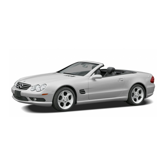
- Page 2 SL 500 SL 55 AMG SL 600 SL 65 AMG...
- Page 3 Your Mercedes-Benz represents the ef- forts of many skilled engineers and crafts- men. To help assure your driving pleasure, and also the safety of you and your passen-...
-
Page 4: Table Of Contents
Operator’s Manual ... 10 Service and warranty information .. 10 Important notice for California retail buyers and lessees of Mercedes-Benz automobiles ... 11 Maintenance ... 12 Roadside Assistance ... 12 Change of address or ownership... 12 Operating your vehicle outside the USA or Canada... - Page 5 Contents Safety and Security ... 63 Occupant safety... 64 Airbags ... 65 Seat belts ... 71 Roll bar... 75 Children in the vehicle... 76 Panic alarm ... 81 Activating ... 81 Deactivating ... 81 Driving safety systems... 82 ABS ... 83 BAS ...
- Page 6 Settings menu... 146 Trip computer menu... 157 TEL menu* ... 159 Automatic transmission... 162 Gear selector lever position ... 164 Driving tips... 166 Gear ranges ... 167 Automatic shift program ... 168 Gear selector lever one-touch gearshifting ... 169 Steering wheel gearshift control one-touch gearshifting ...
- Page 7 Contents Operation ... 255 The first 1000 miles (1500 km) ... 256 Driving instructions... 257 Drive sensibly – save fuel ... 257 Drinking and driving ... 257 Pedals ... 257 Power assistance ... 258 Brakes ... 258 Driving off... 260 Parking ...
- Page 8 Practical hints ... 331 What to do if … ... 332 Lamps in the instrument cluster .. 332 AIRBAG OFF indicator lamp ... 344 Vehicle status messages in the multifunction display... 345 Where will I find ...? ... 383 First aid kit ... 383 Vehicle tool kit, jack, and spare wheel...
- Page 9 Contents Fuels, coolants, lubricants, etc..445 Capacities ... 445 Engine oils... 447 Engine oil additives ... 447 Air conditioning refrigerant ... 447 Brake fluid ... 447 Premium unleaded gasoline ... 448 Fuel requirements ... 448 Gasoline additives ... 449 Coolants...
-
Page 10: Introduction
Product information Please observe the following in your own best interest: We recommend using Genuine Mercedes-Benz parts as well as conversion parts and accessories explicitly approved by us for your vehicle model. We have tested these parts to determine their reliability, safety and special suitabili- ty for Mercedes-Benz vehicles. -
Page 11: Operator's Manual
Therefore, you may find explanations for optional equipment not installed in your vehicle. If you have any questions about the operation of any equipment, your au- thorized Mercedes-Benz Center will be glad to demonstrate the proper proce- dures. We continuously strive to improve our... -
Page 12: Mercedes-Benz Automobiles
30 calendar days. Written notification should be sent to us, not a dealer, at Mercedes-Benz USA, LLC, Customer Assistance Center, One Mercedes Drive, Montvale, NJ 07645-0350. -
Page 13: Maintenance
Always have the Maintenance Booklet with you when you take the vehicle to your au- thorized Mercedes-Benz Center for ser- vice. The service advisor will record each service in the booklet for you. Roadside Assistance... -
Page 14: Operating Your Vehicle Outside The Usa Or Canada
Certain Mercedes-Benz models are avail- able for delivery in Europe under our Euro- pean Delivery Program. For details, consult an authorized Mercedes-Benz Center or... -
Page 15: Where To Find It
Here you will find all the information you need for your first drive. You should read this section first if this is your first Mercedes-Benz vehicle or if you are rent- ing or borrowing this vehicle. Safety and Security Here you will find descriptions of the safety and security features in your vehicle. -
Page 16: Symbols
Symbols Trademarks: ® is a registered trademark of DaimlerChrysler. ® HomeLink is a registered trademark of Prince, a Johnson Controls Company. BabySmart is a trademark Siemens Automotive Corp. The following symbols are found in this Operator’s Manual: Optional equipment is identified with an asterisk. -
Page 17: Operating Safety
Electronic malfunctions could seri- ously impair the operating safety of your vehicle. See an authorized Mercedes-Benz Center for repairs or modifications to electronic components. Other improper work or modifications on the vehicle could also have a negative impact on the operating safety of the vehicle. -
Page 18: Problems With Your Vehicle
If you should experience a problem with your vehicle, particularly one that you believe may affect its safe operation, we urge you to immediately contact an authorized Mercedes-Benz Center to have the problem diagnosed and corrected if required. If the matter is... -
Page 19: Reporting Safety Defects
If you believe that your vehicle has a defect which could cause a crash or could cause injury or death, you should immediately inform the National Highway Traffic Safety Administration (NHTSA) in addition to notifying Mercedes-Benz USA, LLC. If NHTSA receives similar complaints, it may open an investigation, and if it finds that a safety defect exists in a group of vehicles, it may order a recall and remedy campaign. -
Page 20: Vehicle Data Recording
Vehicle data recording Information regarding electronic recording devices (Including notice pursuant to California Code § 9951) Please note that your vehicle is equipped with devices that can record vehicle systems data and, if equipped with the Tele Aid system, may transmit some data in certain accidents. This information helps, for example, to diagnose vehicle systems after a collision and to continuously improve vehicle safety. -
Page 22: At A Glance
At a glance Cockpit Instrument cluster Multifunction steering wheel Center console Overhead control panel Door control panel... -
Page 23: Cockpit
At a glance Cockpit... - Page 24 Item Page 1 Parking brake pedal 2 Hood lock release 3 Parking brake release han- 4 Door control panel 5 Exterior lamp switch 53, 123 6 Headlamp washer button 7 Combination switch Turn signals Windshield wipers High beam Item Page 8 Steering wheel gearshift control (SL 55 AMG, SL 65 AMG,...
-
Page 25: Instrument Cluster
At a glance Instrument cluster... - Page 26 Item Page 1 Coolant temperature gauge with: D Coolant temperature warning lamp 2 Speedometer with: ; Brake warning lamp, USA only 3 Brake warning lamp, Canada only v ABS/ESP ® warning lamp E Distronic* indicator lamp (white) or warning lamp (red) Vehicles without Distronic*: Warning lamp without function.
- Page 27 At a glance Instrument cluster...
- Page 28 Item Page 5 Tachometer with: A High beam head- lamp indicator ú Engine malfunction indicator lamp, USA only ± Engine malfunction indicator lamp, Canada only C Roll bar warning lamp - Antilock Brake Sys- tem (ABS) indicator lamp Item Page 1 Supplemental Restraint System (SRS) indicator lamp...
-
Page 29: Multifunction Steering Wheel
At a glance Multifunction steering wheel Item Page 1 Left multifunction display in the speedometer 2 Right multifunction display in the tachometer Operating the control sys- 3 Selecting the submenu or setting the volume: Press button ç down/to decrease æ up/to increase 4 Telephone*: Press button s to take a call... -
Page 30: Important Notice For California Center Console
Center console Upper part Item Page 1 Central locking switch 2 Hazard warning flasher on/off switch 3 Central unlocking switch 4 Center and side air vent ad- justment 5 COMAND system, see sepa- rate operating instructions 6 Automatic climate control panel 7 Right cup holder 8 KEYLESS-GO* start/stop... -
Page 31: Lower Part
At a glance Center console Lower part Item Page 1 Parking assist (Parktronic system)* deactivation switch 2 Active Body Control (ABC) button 3 Tow-away alarm switch 4 Retractable hardtop 195, open/close control with buttons for roll bar 5 Exterior rear view mirror ad- justment Item Page... -
Page 32: Overhead Control Panel
Overhead control panel Item Page 1 Left reading lamp on/off 2 Temperature sensor for au- tomatic climate control 3 Right reading lamp on/off 4 Interior lighting control 5 Rear view mirror 44, 177 6 Garage door opener 7 Hands-free microphone for Tele Aid (emergency call system), telephone* and voice control system* (see... -
Page 33: Door Control Panel
At a glance Door control panel Item Page 1 Door handle 2 Switches for opening/clos- ing front and rear side win- dows 3 Memory function (for stor- ing seat, mirror and steer- ing wheel settings) 4 Seat heating switch Seat ventilation* switch 5 Seat adjustment switch 6 Remote trunk lid release switch... -
Page 34: Getting Started
Getting started Unlocking Adjusting Driving Parking and locking... -
Page 35: Unlocking
Getting started Unlocking The “Getting started” section provides an overview of the vehicle’s most basic func- tions. First-time Mercedes-Benz owners should pay special attention to the infor- mation given here. If you are already familiar with the basic functions described here, the “Controls in detail”... -
Page 36: Unlocking With Keyless-Go
Unlocking with KEYLESS-GO* With the KEYLESS-GO function, you can lock and unlock the vehicle without using the remote control buttons on the SmartKey and start the engine without in- serting the SmartKey in the starter switch. The function of the SmartKey overrules the KEYLESS-GO function. -
Page 37: Starter Switch Positions
Getting started Unlocking Starter switch positions Warning! When leaving the vehicle, always remove the SmartKey or the SmartKey with KEYLESS-GO* from the starter switch, take it with you, and lock the vehicle. Do not leave children unattended in the vehicle, or with access to an unlocked vehicle. - Page 38 If the SmartKey cannot be turned in the starter switch, the starter battery may not be sufficiently charged. Check the starter battery and charge it if necessary ( page 413). Get a jump start ( page 419). To prevent accelerated battery dis- charge or a completely discharged bat- tery, always remove the SmartKey from the starter switch when the engine is...
- Page 39 Getting started Unlocking Ignition (or Position 2) Press the KEYLESS-GO start/stop but- ton twice. This supplies power for all electrical consumers. All lamps (except high beam headlamp indicator lamp and turn signal indicator lamps unless acti- vated) in the instrument cluster come If you now press the KEYLESS-GO start/stop button once, the power sup- ply is again switched off.
-
Page 40: Adjusting
Adjusting Warning! All seat, head restraint, steering wheel, and rear view mirror adjustments, as well as fas- tening of seat belts, must be done before the vehicle is put into motion. Seats Warning! Do not adjust the driver’s seat while driving. Adjusting the seat while driving could cause the driver to lose control of the vehicle. - Page 41 Adjusting Warning! Children 12 years old and under must never ride in this vehicle, except in a Mercedes-Benz authorized BabySmart compatible child seat, which operates with the BabySmart system installed in the ve- hicle to deactivate the passenger front air- bag when it is properly installed.
- Page 42 Seat height Press the switch up or down in direc- tion of arrow 2. Seat cushion tilt Press the switch up or down in direction of arrow 3 until your upper legs are lightly supported. Seat cushion depth Press the switch forward or backward in direction of arrow 4 until your legs are supported comfortably.
-
Page 43: Steering Wheel
Getting started Adjusting Steering wheel Warning! Do not adjust the steering wheel while driv- ing. Adjusting the steering wheel while driv- ing could cause the driver to lose control of the vehicle. When leaving the vehicle, always remove the SmartKey or the SmartKey with KEYLESS-GO* from the starter switch, take it with you, and lock the vehicle. - Page 44 Easy-entry/exit feature This feature allows for easier entry into and exit from the vehicle. When entering and exiting the vehicle, the steering wheel is in its uppermost position. The easy-entry/exit feature can be activat- ed or deactivated in the Convenience sub- menu of the control system ( page 156).
-
Page 45: Mirrors
Getting started Adjusting If the current position for the steering wheel is in the uppermost tilt position, the steering wheel will no longer be able to move upward when the easy-entry/exit feature is activated. The adjustment procedure is briefly in- terrupted when the engine is started. - Page 46 The buttons are located on the lower part of the center console. 1 Driver’s side exterior rear view mirror button 2 Passenger-side exterior rear view mir- ror button 3 Adjustment button Switch on the ignition ( page 36). Press button 1 for the left mirror or button 2 for the right mirror.
-
Page 47: Driving
( page 64). Warning! Children 12 years old and under must never ride in this vehicle, except in a Mercedes-Benz authorized BabySmart compatible child seat, which operates with the BabySmart system installed in the ve- hicle to deactivate the passenger front air- bag when it is properly installed. - Page 48 Infants and small children must be seated in an appropriate BabySmart compatible in- fant or child restraint system, which is prop- erly secured with the vehicle’s seat belt, fully in accordance with the child seat man- ufacturer’s instructions. A child’s risk of serious or fatal injuries is significantly increased if the child restraints are not properly secured in the vehicle and the child is not properly secured in the child...
- Page 49 Do not bleach or dye seat belts as this may severely weaken them. In a crash, they may not be able to provide adequate protection. Damaged seat belts or belts that were highly stressed in an accident must be replaced. Contact an authorized Mercedes-Benz Center.
-
Page 50: Starting The Engine
Starting the engine Warning! Inhalation of exhaust gas is hazardous to your health. All exhaust gas contains carbon monoxide, and inhaling it can cause uncon- sciousness and possible death. Do not run the engine in confined areas (such as a garage) which are not properly ventilated. - Page 51 Get a jump start ( page 419). If the engine does not start after several starting attempts, there could be a mal- function in the engine electronics or in the fuel supply system. Notify an authorized Mercedes-Benz Center.
-
Page 52: Parking Brake
Parking brake 1 Parking brake pedal 2 Release handle Warning! When leaving the vehicle, always remove the SmartKey or the SmartKey with KEYLESS-GO* from the starter switch, take it with you, and lock the vehicle. Do not leave children unattended in the vehicle, or with access to an unlocked vehicle. - Page 53 Getting started Driving Warning! On slippery road surfaces, never downshift in order to obtain braking action. This could result in drive wheel slip and reduced vehi- cle control. Your vehicle’s ABS will not pre- vent this type of loss of control. In order to avoid damage to the trans- mission: Wait for the gear selection process...
-
Page 54: Switching On Headlamps
Switching on headlamps Low beam headlamps The exterior lamp switch is located on the dashboard to the left of the steering wheel. Exterior lamp switch 1 Off 2 Low beam headlamps on Turn the exterior lamp switch to position B. The low beam headlamps come on. -
Page 55: Windshield Wipers
Getting started Driving The combination switch resets automati- cally after major steering wheel move- ments. To signal minor directional changes such as changing lanes, press combi- nation switch only to point of resis- tance and release. The corresponding turn signals will flash three times. Windshield wipers The combination switch is located on the left of the steering column. - Page 56 Intermittent wiping Do not leave windshield wipers in inter- mittent setting when vehicle is taken to an automatic car wash or during wind- shield cleaning. Windshield wipers will operate in the presence of water sprayed on the windshield, and wind- shield wipers may be damaged as a re- sult.
-
Page 57: Problems While Driving
An ignition cable may be damaged. The engine electronics may not be op- erating properly. Unburned gasoline may have entered the catalytic converter and damaged it. Give very little gas. Have the problem repaired by an au- thorized Mercedes-Benz Center as soon as possible. - Page 58 Do not start the engine under any cir- cumstances. Notify local fire and/or police authori- ties. If the extent of the damage cannot be de- termined: Notify an authorized Mercedes-Benz Center. If no damage can be determined on the major assemblies fuel system engine mount: Start the engine in the usual manner.
-
Page 59: Parking And Locking
Getting started Parking and locking You have now completed your first drive. You have properly stopped and parked your vehicle. End your drive as follows. Warning! With the engine not running, there is no power assistance for the brake and steering systems. -
Page 60: Parking Brake
Parking brake 1 Parking brake pedal 2 Release handle Step firmly on parking brake pedal 1. When the engine is running, the indica- tor lamp ; (USA only) or 3 (Canada only) in the instrument cluster will be illuminated. Warning! When leaving the vehicle, always remove the SmartKey or the SmartKey with KEYLESS-GO* from the starter switch, take... -
Page 61: Turning Off The Engine
Getting started Parking and locking Turning off the engine Place the gear selector lever in position P. Apply the parking brake ( page 59). Always set the parking brake in addi- tion to shifting to position P. On slopes, turn the front wheels to- wards the road curb. -
Page 62: Releasing Seat Belts
Such damage is not covered by the Mercedes-Benz Limited Warranty. Damaged seat belts must be replaced. Contact an authorized Mercedes-Benz Light Truck Center. - Page 63 Getting started Parking and locking Exit the vehicle and close the doors and the trunk. Opening a door causes the windows on that side of the car to open slightly. They will return to the up position when the door is closed. Locking with the SmartKey Press the lock button ‹...
-
Page 64: Safety And Security
Safety and Security Occupant safety Panic alarm Driving safety systems Anti-theft systems... -
Page 65: Occupant Safety
Safety and Security Occupant safety In this section you will learn the most im- portant facts about the restraint systems of the vehicle. The restraint systems are Seat belts Emergency tensioning device Airbags Child seats Child seat recognition As independent systems, their protective effects work in conjunction with each oth- For information on infants and children traveling with you in the vehicle and re-... -
Page 66: Airbags
SRS self-check has detected a malfunction. For your safety, we strongly recommend that you visit an authorized Mercedes-Benz Center immediately to have the system checked; otherwise the SRS may not be activated when needed in an acci-... - Page 67 If you have any prob- lems, please see an authorized Mercedes-Benz Center. Do not lean with your head or chest close to the steering wheel or dash- board.
- Page 68 Mercedes-Benz Center at an addi- tional cost. Please contact your local authorized Mercedes-Benz Center or call our Customer Assistance Center at 1-800-FOR-MERCedes (1-800-367-6372) for details.
- Page 69 Safety and Security Occupant safety Airbags are designed to activate only in certain frontal impacts (front airbags, driver-side knee bag) and side impacts (head-thorax airbags) which exceed preset thresholds. Only during these types of impacts, if of sufficient severi- ty to meet the deployment threshold, will they provide their supplemental protection.
- Page 70 These instructions are available from your authorized Mercedes-Benz Center. Given the considerable deployment speed and the textile structure of the airbags, there is the possibility of abra- sions or other injuries resulting from air- bag deployment.
- Page 71 Safety and Security Occupant safety Front airbags Driver and passenger airbags are de- ployed: in the event of certain frontal impacts if impact exceeds a preset deployment threshold independently of the head-thorax air- bags The airbags will not deploy in impacts which do not exceed the system’s deploy- ment thresholds.
-
Page 72: Seat Belts
Head-thorax airbags The head-thorax airbags are deployed: on the impacted side of the vehicle in impacts exceeding a preset deploy- ment threshold independently of the front airbags The head-thorax airbags are not deployed in impacts which do not exceed the sys- tem’s deployment threshold. - Page 73 Safety and Security Occupant safety Always wear your seat belt. All vehicle occupants always need to have their seat belts fastened and wear them properly. In addition, applicable motor vehicle safety laws require you to wear seat belts. Even where this is not the case, we strongly rec- ommend that all vehicle occupants have their seat belts fastened and wear them properly.
- Page 74 Only use seat belts which have been ap- proved by Mercedes-Benz. Do not make any modifications to the seat belts. This can lead to unintended activation or to failure.
- Page 75 Safety and Security Occupant safety Never wear the shoulder belt under your arm, against your neck or off your shoul- der. In a crash, your body would move too far forward. That would increase the chance of head and neck injuries. The belt would also apply too much force to the ribs or abdomen, which could se- verely injure internal organs such as...
-
Page 76: Roll Bar
When disposing of the emergency tension- ing device, our safety instructions must be followed. These are available at your autho- rized Mercedes-Benz Center. Do not place objects heavier than 20 lbs (9 kg) on the front passenger seat. This could cause the front or side... -
Page 77: Children In The Vehicle
For safety reasons, drive only with the roll bar upright until the malfunction is repaired. Have your vehicle checked at an authorized Mercedes-Benz Center. Raising the roll bar Lift the switch for the retractable hard- top. Press and hold button 2 until the roll bar is raised. - Page 78 Warning! Children 12 years old and under must never ride in this vehicle, except in a Mercedes-Benz authorized BabySmart compatible child seat, which operates with the BabySmart system installed in the ve- hicle to deactivate the passenger front air- bag when it is properly installed.
- Page 79 Special BabySmart compatible child seats, designed for use with the Mercedes-Benz system and available at any authorized Mercedes-Benz Center, are required for use with the BabySmart air- bag deactivation system. With the special child seat properly installed, the passenger...
- Page 80 6 seconds and then goes out. If the indicator lamp should not come on or is continuously lit, the system is not func- tioning. You must see an authorized Mercedes-Benz Center before seating any child on the passenger seat. Warning! The BabySmart...
- Page 81 Safety and Security Occupant safety Warning! Do not place powered-on laptops, cell phones, electronic tags such as those used on ski passes, and like electronic devices on the passenger seat. Signals from such de- vices may interfere with the BabySmart system.
-
Page 82: Panic Alarm
Panic alarm An audible alarm and flashing exterior lamps will operate for approximately minutes. 1 Â button USA only: This device complies with Part 15 of the FCC Rules. Operation is subject to the following two conditions: (1) This device may not cause harmful interference, and (2) this device must accept any inter- ference received, including interfer-... -
Page 83: Driving Safety Systems
Safety and Security Driving safety systems In this section you will find information on the following driving safety systems: ABS (Antilock Brake System) BAS (Brake Assist System) ® (Electronic Stability Program) Electro-hydraulic brake system In winter operation, the maximum ef- fectiveness of the ABS, the BAS, the ®... -
Page 84: Abs
Warning! Do not pump the brake pedal. Use firm, steady brake pedal pressure instead. Pump- ing the brake pedal defeats the purpose of the ABS and significantly reduces braking effectiveness. The Antilock Brake System (ABS) regulates the brake pressure so that the wheels do not lock during braking. -
Page 85: Bas
Safety and Security Driving safety systems Warning! The ABS cannot prevent the natural laws of physics from acting on the vehicle, nor can it increase braking or steering efficiency be- yond that afforded by the condition of the vehicle brakes and tires or the traction afforded. -
Page 86: Esp
® ® The Electronic Stability Program (ESP ) is operational as soon as the engine is run- ning and monitors the vehicle's traction (force of adhesive friction between the tires and the road surface) and handling. ® The ESP recognizes when a wheel is spin- ning or if the vehicle starts to skid. - Page 87 Safety and Security Driving safety systems ® Because of the ESP ’s automatic oper- ation, the engine must be shut off (SmartKey in starter switch position 0 or 1 or KEYLESS-GO* start/stop but- ton in position 0 or 1) when the parking brake is being tested on a brake test dynamometer the vehicle is being towed with the...
- Page 88 Avoid spinning of a drive wheel for an ® extended period with the ESP switched off. This may cause serious damage to the drivetrain which is not covered by the Mercedes-Benz Limited Warranty. Safety and Security Driving safety systems ®...
-
Page 89: Electro-Hydraulic Brake System
Safety and Security Driving safety systems Electro-hydraulic brake system The electro-hydraulic brake system com- bines a hydraulic brake circuit with elec- tronically controlled brake servo assistance. You have increased braking safety and improved braking comfort. Warning! Never ignore a brake malfunction indicated in the speedometer display, for example by the ;... - Page 90 Have brake pad replacement and other work on the electro-hydraulic brake system car- ried out by qualified technicians only. Con- tact an authorized Mercedes-Benz Center for further information. The electro-hydrau- lic brake system must be deactivated prior to working on the system. High pressure is intermittently built up in the system as part of its automatic self-test.
- Page 91 Only Mercedes-Benz approved compo- nents (e.g. brake pads) should be in- stalled on your vehicle. Brake pads not approved by Mercedes-Benz may im- pair the safety of your vehicle.
-
Page 92: Anti-Theft Systems
In case the engine cannot be started (yet the vehicle’s battery is charged), the system is not operational. Contact an authorized Mercedes-Benz Center or call 1-800-FOR-MERCedes (in the USA), or 1-800-387-0100 (in Canada). Safety and Security Anti-theft systems... - Page 93 Safety and Security Anti-theft systems The alarm system will also be triggered when someone attempts to raise the vehicle unlocking and opening the driver’s door with the mechanical key someone opens a door from the inside someone opens the trunk lid with the emergency release button If the alarm stays on for more than 30 seconds, a call to the Response...
-
Page 94: Tow-Away Alarm
Canceling the alarm To cancel the alarm: With the SmartKey Insert the SmartKey in the starter switch. Press the Œ or ‹ button on the SmartKey. With KEYLESS-GO* Grasp an outside door handle. The SmartKey with KEYLESS-GO must be within 3 ft. (1 m) of the vehicle. Press the KEYLESS-GO start/stop but- ton ( page 37). - Page 95 Safety and Security Anti-theft systems 1 Tow-away alarm off button 2 Indicator lamp Switch off the ignition and remove the SmartKey from the starter switch. You cannot disarm the tow-away alarm if the ignition is switched on. Press button 1. The indicator lamp 2 in the switch comes on briefly.
-
Page 96: Controls In Detail
Controls in detail Locking and unlocking Seats Memory function Lighting Instrument cluster Control system Automatic transmission Good visibility Automatic climate control Power windows Retractable hardtop Driving systems Useful features... -
Page 97: Locking And Unlocking
Controls in detail Locking and unlocking In the “Controls in detail” section you will find detailed information on how to oper- ate the equipment installed on your vehi- cle. If you are already familiar with the basic functions of your vehicle, this section will be of particular interest to you. - Page 98 Warning! When leaving the vehicle, always remove the SmartKey from the starter switch, take it with you, and lock the vehicle. Do not leave children unattended in the vehicle, or with access to an unlocked vehicle. It is possible for children to open a locked door from the inside, which could result in an accident and/or serious injury.
- Page 99 Controls in detail Locking and unlocking Factory setting Global unlocking Press button Œ. All turn signals flash once. The locking knobs in the doors move up. The anti-theft alarm system is disarmed. The vehicle will lock again automatically and reactivate the alarm system within ap- proximately 40 seconds of unlocking if: neither door nor trunk is opened the SmartKey is not inserted in the...
- Page 100 ( page 413). Use the mechanical key to lock or unlock the doors ( page 387). If the SmartKey is malfunctioning, con- tact an authorized Mercedes-Benz Center. Checking the batteries Press button ‹ or Œ. Battery check lamp 5 ( page 96) comes on briefly to indicate that the SmartKey batteries are in order.
-
Page 101: Smartkey With Keyless-Go
Report the loss of the SmartKey or the mechanical key to your car insurance company immediately. If necessary, have the mechanical lock replaced. Your authorized Mercedes-Benz Center will be glad to supply you with a replace- ment. SmartKey with KEYLESS-GO* Vehicles equipped with KEYLESS-GO come... - Page 102 SmartKey with KEYLESS-GO 1 ‹ Lock button 2 Š Unlock button for the trunk lid 3 Mechanical key locking tab 4 Œ Unlock button 5 Battery check lamp 6  Panic button ( page 81) For information on using the SmartKey buttons, see “SmartKey”...
- Page 103 Controls in detail Locking and unlocking Canada only: This device complies with RSS-210 of Industry Canada. Operation is subject to the following two conditions: (1) This device may not cause interfer- ence, and (2) this device must accept any inter- ference received, including interfer- ence that may cause undesired operation of the device.
- Page 104 This does not apply if, after starting, the selector lever is still in position P and the SmartKey is then inserted in the starter switch. The SmartKey will then have priority over the KEYLESS-GO function and the vehicle’s electrical system will operate according to the position of the SmartKey in the starter switch, even stopping the engine.
- Page 105 Controls in detail Locking and unlocking Global locking Press lock button on an outside door handle ( page 62) or trunk ( page 105). With the trunk and all doors closed, all turn signals flash three times. The lock- ing knobs in the doors move down. The anti-theft alarm system is armed.
- Page 106 Use the mechanical key to lock or unlock the doors ( page 387). If the SmartKey with KEYLESS-GO is malfunctioning, contact an authorized Mercedes-Benz Center. Global locking using the lock button on the trunk lid Vehicles with KEYLESS-GO*: To pre-...
- Page 107 SmartKey battery is dis- charged. Replace the battery ( page 389). You can obtain the required battery at any authorized Mercedes-Benz Center. Unlocking the trunk You can unlock the trunk separately. A minimum height clearance of 6.2 ft (1.88 m) is required to open the trunk lid.
-
Page 108: Opening The Doors From The Inside
Opening the doors from the inside You can open a locked door from the in- side. Open door only when conditions are safe to do so. 1 Locking knob 2 Inside door handle Pull on door handle 2. If the door was locked, locking knob 1 will move up. -
Page 109: Opening The Trunk
Controls in detail Locking and unlocking Opening the trunk A minimum height clearance of 6.2 ft (1.88 m) is required to open the trunk lid. Always make sure that there is suffi- cient overhead clearance. Opening the trunk from the outside The handle is located above the rear li- cense plate recess. -
Page 110: Closing The Trunk
1 Remote trunk lid release switch 2 Indicator lamp Pull remote trunk lid release switch 1. The trunk lid unlocks. Indicator lamp 2 comes on and remains lit until the trunk is closed again. Lift the trunk lid. To facilitate trunk loading and unload- ing when the hardtop is retracted, you can raise the hardtop from its storage position in the trunk using the loading... -
Page 111: Valet Locking
Controls in detail Locking and unlocking Close trunk lid with hands placed flat on trunk lid. Warning! Only drive with the trunk closed. Among oth- er dangers, such as blocked visibility, ex- haust fumes may enter the vehicle interior. If the vehicle was previously centrally locked, the trunk lid will lock automati- cally when closed ( page 109). -
Page 112: Trunk Lid Emergency Release
1 Neutral position 2 Locked Close the trunk ( page 109). Pull the mechanical key out of the SmartKey ( page 385). Insert the mechanical key in the trunk lid lock. Turn the mechanical key clockwise to position 2 and remove the mechani- cal key in that position to lock the trunk. -
Page 113: Automatic Central Locking
Controls in detail Locking and unlocking The emergency release button unlocks the trunk while the vehicle is standing still or in motion. Illumination of the emergency release but- ton: The button flashes for 30 minutes after opening the trunk. The button flashes for 60 minutes after closing the trunk. -
Page 114: Locking And Unlocking From The Inside
Locking and unlocking from the inside You can lock or unlock the vehicle from in- side using the central locking switches. This can be useful, for example, if you want to unlock the passenger door from the in- side or want to lock the vehicle before starting to drive. - Page 115 Controls in detail Locking and unlocking If the vehicle was previously centrally locked using the SmartKey or the SmartKey with KEYLESS-GO*, it will not unlock using the central locking switch. If the vehicle was previously locked with the central locking switch while in the global remote control mode, the complete vehicle is un- locked when a door is opened from...
-
Page 116: Seats
Seats For more information on seat adjustment, see “Seat adjustment” ( page 40). Moving the seats forward and backward You can move the seats forward and back to facilitate loading and unloading. Warning! When moving the seats, be sure that no one can be caught by them. -
Page 117: Lumbar Support
Controls in detail Seats Lumbar support You can adjust the contour of the seat’s lumbar support to help enhance support to your spine. The thumbwheel is located on the lower side of the seat. 1 Thumb wheel Switch on the ignition ( page 36). Set the lumbar support between 0 and 5. -
Page 118: Seat Heating
Massage function (PULSE) You can reduce muscle tension during long trips by periodically using the massage function. Press button 3. The indicator lamp on button 3 comes on. The air cushions in the lumbar re- gion inflate and deflate rhythmically. The massage function switches off au- tomatically after approximately 8 minutes. - Page 119 Controls in detail Seats Switching on rapid seat heating Press upper switch position 2. Both red indicator lamps on the switch come on. The system switches to normal heating mode after approximately 5 minutes. Only the right-hand indicator lamp re- mains lit.
- Page 120 Switching on seat heating Press upper switch position 1 twice. A red indicator lamp on the switch comes on. Switching off seat heating Press upper switch position 1 again. The seat heating will be automatically switched off after approximately 30 minutes. Switching on rapid seat heating Press upper switch position 1 once.
-
Page 121: Seat Ventilation
Controls in detail Seats Seat ventilation* The switch is located on the door. The blue indicator lamps on the switch indicate the selected ventilation level: Level Three indicator lamps on (highest level) Two indicator lamps on One indicator lamp on (lowest level) No indicator lamp on 1 Seat ventilation switch... -
Page 122: Memory Function
Memory function Prior to operating the vehicle, the driver should check and adjust the seat height, seat position fore and aft, and seat back- rest angle if necessary, to ensure adequate control, reach and comfort. The head re- straint should also be adjusted for proper height. -
Page 123: Storing Positions Into Memory
Controls in detail Memory function Storing positions into memory Adjust the seats, steering wheel and exterior rear view mirrors to the de- sired position ( page 39). Press memory button M. Release memory button and press a stored position button 1, 2, or 3 within 3 seconds. -
Page 124: Lighting
Relevant information can be obtained at any authorized Mercedes-Benz Center. Exterior lamp switch The exterior lamp switch is located on the dashboard to the left of the steering wheel. - Page 125 Controls in detail Lighting With the SmartKey removed from the starter switch or the engine turned off with KEYLESS-GO* and the driver’s door open, a warning sounds if the parking lamps or the low beam head- lamps are switched on. The message $ Turn off lamps appears in the multifunction display.
- Page 126 Turn the exterior lamp switch to posi- tion U. With the SmartKey in starter switch position 1 or the KEYLESS-GO start/stop button pressed once, only the parking lamps will switch on and off automatically. When the engine is running, the low beam headlamps, the tail and parking lamps, the license plate lamps, and the side marker lamps will switch on and...
- Page 127 Controls in detail Lighting Canada only: The daytime running lamp mode is manda- tory and therefore in a constant mode. When the engine is running and you shift from a driving position to position N or P, the low beam headlamps will switch off with a three-minute delay.
-
Page 128: Corner-Illuminating Front Fog
The fog lamps cannot be switched on with the exterior lamp switch in posi- tion U. To switch on the fog lamps, turn the exterior lamp switch to posi- tion B first. Front fog lamps Switch on the low beam headlamps ( page 53). - Page 129 Controls in detail Lighting Corner-illuminating front fog lamps will only come on in low ambient lighting conditions. The corner-illuminating front fog lamps function is not available at a vehicle speed above 25 mph (40 km/h). Driving forward Switching on corner-illuminating front fog lamps Depending on whether you are turning left or right, switch on the left or right...
-
Page 130: Combination Switch
Combination switch The combination switch is located on the left of the steering column. Combination switch 1 High beam 2 High beam flasher High beam Turn the exterior lamp switch to B or to U ( page 123). Push the combination switch in direc- tion of arrow 1 to switch on the high beam headlamps. -
Page 131: Interior Lighting
Controls in detail Lighting Switching on the hazard warning flasher Press hazard warning flasher switch 1. All turn signals are flashing. With the hazard warning flasher acti- vated and the combination switch set for either left or right turn, only the re- spective turn signals will operate when the ignition is switched on. -
Page 132: Courtesy Lighting
Deactivating Slide switch 4 to the right. The interior lighting and the entry/exit lamps remain switched off in darkness, even when you unlock the vehicle open a door remove the SmartKey from the starter switch open the trunk Manual control Switching lamps on Press switch 3. -
Page 133: Instrument Cluster
Controls in detail Instrument cluster For a full view illustration of the instrument cluster, see “Instrument cluster” ( page 24). The instrument cluster is activated when open a door switch on the ignition press the reset button ( page 24) switch on the exterior lamps Opening a door will activate the instrument cluster only for about 30 seconds. -
Page 134: Coolant Temperature Gauge
The engine should not be operated with the coolant temperature above 248°F (120°C). Doing so may cause serious en- gine damage which is not covered by the Mercedes-Benz Limited Warranty. Trip odometer Make sure you are viewing the trip odometer display ( page 135). -
Page 135: Outside Temperature Indicator
Controls in detail Instrument cluster Outside temperature indicator Warning! The outside temperature indicator is not de- signed to serve as an ice-warning device and is therefore unsuitable for that purpose. Indicated temperatures just above the freez- ing point do not guarantee that the road sur- face is free of ice. -
Page 136: Control System
Control system The control system is activated as soon as the SmartKey in the starter switch is turned to position 1 or as soon as the KEYLESS-GO start/stop button is in posi- tion 1. The control system enables you to call up information about your vehicle change vehicle settings For example, you can use the control sys-... -
Page 137: Multifunction Steering Wheel
Controls in detail Control system Multifunction steering wheel The displays in the multifunction display and the settings in the control system are controlled by the buttons on the multifunc- tion steering wheel. 1 Left multifunction display in the speedometer 2 Right multifunction display in the tachometer Operating the control system 3 Selecting the submenu or setting the... - Page 138 The individual functions are then found within the relevant menu (radio or CD op- erations under AUDIO , for example). These functions serve to call up relevant informa- tion or to customize the settings for your vehicle. It is helpful to think of the menus, and the functions within each menu, as being ar- ranged in a circular pattern.
-
Page 139: Menus
Controls in detail Control system Menus This is what you will see when you scroll through the menus. The table below provides an overview of the individual menus. - Page 140 Menus, submenus and functions Menu 1 Menu 2 Menu 3 Standard dis- AUDIO play ( page 140) ( page 141) ( page 143) ( page 143) ( page 144) Digital speedom- Selecting Show route eter/Outside radio station guidance temperature instructions, current direction traveled...
-
Page 141: Standard Display Menu
Controls in detail Control system The headings used in the menus table are designed to facilitate navigation within the system and are not neces- sarily identical to those shown in the control system displays. The first function displayed in each menu will automatically show you which part of the system you are in. -
Page 142: Audio Menu
AUDIO menu The functions in the AUDIO menu operate the audio equipment which you currently have turned on. If no audio equipment is currently turned on, the message AUDIO off appears in the right multifunction display. The following functions are available: Function Page Selecting radio station... - Page 143 Additional optional satellite radio equipment and a subscription to satel- lite radio service provider are required for satellite radio operation. Contact an authorized Mercedes-Benz Center for details and availability for your vehicle. For more information, refer to separate COMAND operating instructions.
-
Page 144: Nav Menu
NAV menu menu contains the functions need- ed to operate your navigation system. Press button è or ÿ repeatedly until you see the message in the left multifunction display. The message shown in the multifunction display depends on the status of the navi- gation system: With COMAND switched off, the mes- sage... -
Page 145: Vehicle Status Message Memory Menu
Mercedes-Benz Center to address the malfunction and warning messages ( page 345). Press button è or ÿ repeatedly... - Page 146 Vehicle status messages have been recorded If conditions have occurred causing status messages to be recorded, the number of messages appears in the right multifunc- tion display: 1 Number of recorded status messages Press button k or j. The stored messages will now be dis- played in the order in which they have occurred.
-
Page 147: Settings Menu
Controls in detail Control system Settings menu In the Settings menu there are two func- tions: The function Reset , with which you can reset all the settings to those set at the factory. A collection of submenus with which you can make individual settings for your vehicle. - Page 148 Submenus in the Settings menu Press button j. In the right multifunction display you see the collection of submenus. Press button ç. The selection marker moves to the next submenu. The submenus are arranged by hierarchy. Scroll down with the ç button, scroll up with the æ...
- Page 149 Controls in detail Control system The table below shows what settings can be changed within the various menus. De- tailed instructions on making individual settings can be found on the following pag- Instrument cluster Time Selecting standard Synchronizing time with display head unit Selecting speedometer...
- Page 150 Instrument cluster submenu Access the Inst. cluster submenu via Settings menu. Use the Inst. clus- submenu to change the instrument cluster display settings. The following functions are available: Function Page Selecting standard display Selecting speedometer display mode Selecting language Selecting standard display Move the selection marker with button æ...
- Page 151 Controls in detail Control system Selecting language Move the selection marker with button æ or ç to the Inst. cluster submenu. Press button j or k repeatedly until the message Text appears in the multifunction display. The selection marker is on the current setting.
- Page 152 Press æ or ç enable or disable this feature. When you set this feature to , the time displayed in the multifunction display is automatically synchronized with the time of the COMAND system. For information on setting the time, re- fer to the separate COMAND operating instructions.
- Page 153 Controls in detail Control system Lighting submenu Access the Lighting submenu via the Settings menu. Use the Lighting sub- menu to change the lamp and lighting set- tings on your vehicle. The following functions are available: Function Page Setting daytime running lamp mode (USA only) Setting locator lighting Setting night security illumina-...
- Page 154 For safety reasons, resetting the Lighting submenu to factory settings while driving ( page 147) will not de- activate the daytime running lamp mode. The following message appears in the multifunction display: Cannot be fully reset to factory settings when driving Setting locator lighting With the locator lighting feature activated...
- Page 155 Controls in detail Control system Setting night security illumination (Exterior lamps delayed switch-off) Use this function to set whether you would like the exterior lamps to illuminate during darkness after exiting the vehicle and clos- ing the doors. With the delayed switch-off feature activat- ed and the exterior lamp switch in position U before the engine is turned off, the following lamps will switch on when the en-...
- Page 156 Interior lighting delayed switch-off Use this function to set whether you would like the interior lighting to remain lit during darkness for approximately 10 seconds after you have removed the SmartKey from the starter switch. Move the selection marker with button æ...
- Page 157 Controls in detail Control system Convenience submenu Access the Convenience submenu via the Settings menu. Use the Convenience sub- menu to change the settings for a number of convenience features. The following functions are available: Function Page Activating easy-entry/exit feature Activating easy-entry/exit feature Use this function to activate and deacti- vate the easy-entry/exit feature...
-
Page 158: Trip Computer Menu
Trip computer menu Use the trip computer menu to call up sta- tistical data on your vehicle. The following information is available: Function Page Fuel consumption statistics after start Fuel consumption statistics since last reset Calling up range (distance to empty) The last function called up will reap- pear the next time you enter the trip computer menu. - Page 159 Controls in detail Control system Fuel consumption since last reset Press button ÿ or è repeatedly until you see the first function of the trip computer menu. Press button j or k repeatedly until you see this message in the left multifunction display: From reset.
-
Page 160: Tel Menu
TEL menu* Warning! A driver’s attention to the road must always be his/her primary focus when driving. For your safety and the safety of others, we rec- ommend that you pull over to a safe location and stop before placing or taking a tele- phone call. - Page 161 Controls in detail Control system Rejecting a call If you do not wish to receive the call, you can choose to reject it. Press button t. You have rejected the call. The caller receives a busy signal. Answering a call When your telephone is ready to receive calls, you can answer a call at any time.
- Page 162 Press button s. The system dials the selected phone number. If the connection is successful, the name of the party you called and the duration of the call will appear in the display. If no connection is made, the control system stores the dialed number in the redial memory.
-
Page 163: Automatic Transmission
Controls in detail Automatic transmission For more information on driving with an automatic transmission, see “Automatic transmission” ( page 49). Your vehicle’s transmission adapts its gear shifting process to your individual driving style by continually adjusting the shift points up or down. These shift point adjust- ments are performed based on current operating and driving conditions. - Page 164 Avoid spinning of a drive wheel for an extended period when driving off on slippery road surfaces. This may cause serious damage to the drivetrain which is not covered by the Mercedes-Benz Limited Warranty. When the gear selector lever is in position D, you can influence transmission...
-
Page 165: Gear Selector Lever Position
Controls in detail Automatic transmission Gear selector lever position Effect ì Park position Gear selector lever position when the vehicle is parked. Place gear selector lever in position P only when vehicle is stopped. The park position is not intended to serve as a brake when the vehicle is parked. - Page 166 Coasting the vehicle, or driving for any other reason with gear selector lever in N can result in transmission damage that is not covered by the Mercedes-Benz Limited Warranty. Warning! Getting out of your vehicle with the gear selector lever not fully engaged in position P is dangerous.
-
Page 167: Driving Tips
Controls in detail Automatic transmission Driving tips Accelerator position Your driving style influences the transmission’s shifting behavior: Less throttle Earlier upshifting More throttle Later upshifting Kickdown Use kickdown when you want maximum acceleration. Press the accelerator past the point of resistance. -
Page 168: Gear Ranges
Gear ranges With the gear selector lever in position D and driving in the automatic shift program C or S ( page 168), you can select a gear range for the automatic transmission to operate within: Gear selector lever ( page 169): You can limit the gear range by pressing the gear selector lever to the left (D-), and reverse the gear range limit by pressing... -
Page 169: Automatic Shift Program
Controls in detail Automatic transmission Automatic shift program The program mode selector switch is located on the lower part of the center console. 1 Program mode selector switch C Comfort For comfort driving S Sport For standard driving The current gear selector lever position and the selected program mode ( ) are indicated in the right multifunction display... -
Page 170: Gear Selector Lever One-Touch Gearshifting
Avoid spinning of a drive wheel for an extended period when driving off on slippery road surfaces. This may cause serious damage to the drivetrain which is not covered by the Mercedes-Benz Limited Warranty. Downshifting Warning! On slippery road surfaces, never downshift in order to obtain braking action. -
Page 171: Steering Wheel Gearshift Control
Avoid spinning of a drive wheel for an extended period when driving off on slippery road surfaces. This may cause serious damage to the drivetrain which is not covered by the Mercedes-Benz Limited Warranty. Steering wheel gearshift control SL 500 with Sport Package* and... - Page 172 You cannot shift with the steering wheel gearshift buttons when the gear selector lever is in position P, N or R. The last selected program mode (C or S) is switched on when the engine is restarted. Downshifting Warning! On slippery road surfaces, never downshift in order to obtain braking action.
- Page 173 Controls in detail Automatic transmission Steering wheel gearshift control SL 55 AMG and SL 65 AMG The steering wheel gearshift buttons are located to the left and right of the steering wheel. 1 Left button: downshift 2 Right button: upshift You cannot shift with the steering wheel gearshift buttons when the gear selector lever is in position P, N or R.
-
Page 174: Manual Shift Program Sl 55 Amg And Sl 65 Amg
Upshifting Briefly press button 2 on the right side of the steering wheel. The transmission will shift to the next higher gear as permitted by the shift program. This action simultaneously extends the gear range of the transmission when you are driving in the automatic program mode (C or S). - Page 175 This may cause serious damage to the drivetrain which is not covered by the Mercedes-Benz Limited Warranty. The program mode selector switch is located on the lower part of the center console.
- Page 176 ( page 24). Otherwise the engine could be damaged which is not covered by the Mercedes-Benz Limited Warranty. Controls in detail Automatic transmission Briefly press the gear selector lever to the right in the D+ direction.
-
Page 177: Emergency Operation (Limp Home Mode)
Move gear selector lever to P. Turn off the engine. Wait at least 10 seconds before restarting. Restart the engine. Move gear selector lever to position D (for second gear) or R. Have the transmission checked at an authorized Mercedes-Benz Center as soon as possible. -
Page 178: Good Visibility
Good visibility For information on windshield wiper opera- tion, see “Windshield wipers” ( page 54). Headlamp cleaning system The button is located on the left side of the dashboard. 1 Headlamp washer button Switch on the ignition ( page 36). Press button 1. -
Page 179: Sun Visors
Controls in detail Good visibility Warning! The auto-dimming function does not react if incoming light is not aimed directly at sen- sors in the interior rear view mirror. The interior rear view mirror and the exterior rear view mirror on the driver’s side do not react, for example, if the wind screen is in- stalled. -
Page 180: Rear Window Defroster
If sunlight enters through a side win- dow, close mirror cover 2 (if open), and disengage sun visor from mounting 1 and pivot sun visor to the side. If the sun visor is disengaged from mounting 1, mirror lamp 3 will switch off. -
Page 181: Automatic Climate Control
Controls in detail Automatic climate control... - Page 182 Item 1 Center air vent, adjustable 2 Cockpit air vent, fixed 3 Side defroster vent 4 Side air vent, adjustable 5 Center air vent, adjustable 6 Thumbwheel for air volume control for right side air vents 7 Thumbwheel for air volume control for center air vents 8 Thumbwheel for air volume control for left side air vents...
- Page 183 Controls in detail Automatic climate control The automatic climate control is operation- al whenever the engine is running. You can operate the climate control system in ei- ther the automatic or manual mode. The system cools or heats the interior depend- ing on the selected interior temperature and the current outside temperature.
-
Page 184: Deactivating The Automatic Climate Control System
Deactivating the automatic climate control system Deactivating Press button ´ ( page 181). The indicator lamp on the button comes on. When the automatic climate control system is switched off, the outside air supply and circulation are also switched off. Only choose this setting when the retractable hardtop is open. -
Page 185: Setting The Temperature
Controls in detail Automatic climate control Air distribution in automatic mode You can separately adjust the air distribu- tion for each side of the passenger com- partment. Activating Press control button 2 or 6 ( page 181). The control button is engaged. The U symbol on the control button comes on. -
Page 186: Adjusting Air Distribution
Adjusting air distribution Use air distribution controls 2 and 6 ( page 181) to separately adjust the air distribution on each side of the passenger compartment. The following symbols are found on the controls: Symbol Function Directs air through the cen- ter and side air vents Directs air to the windows Directs air into the entire... -
Page 187: Adjusting Air Volume
Controls in detail Automatic climate control Adjusting air volume Use air volume control a ( page 181) for both automatic ( page 183) and manual air volume adjustment. Nine blower speeds are available. Press control button a ( page 181). The control button sticks up slightly. -
Page 188: Air Recirculation Mode
Activating Press button P ( page 181). The indicator lamp on the button comes on. The air conditioning switches to the fol- lowing functions automatically: cooling on to dehumidify maximum blower speed and heating power air flows onto the windshield and the front side windows the air recirculation mode is switched off... - Page 189 Controls in detail Automatic climate control Activating Briefly press button , ( page 181). The indicator lamp on the button comes on. The air recirculation mode is activated automatically at high outside temperatures if the concentration of carbon mon- oxide and nitrogen oxide in the out- side air increases, for example in a tunnel The indicator lamp on button , is...
-
Page 190: Air Conditioning
Press and hold button ,. The win- dows will open. The opening of the windows can be im- mediately halted by releasing button ,. At outside temperatures above 79°F (26°C) the system will not automatically switch back to outside air. Air conditioning The air conditioning (cooling) function is operational when the engine is running and... -
Page 191: Residual Heat And Ventilation
The air conditioning cannot be turned on again. Have the air conditioning checked at the nearest authorized Mercedes-Benz Center. Residual heat and ventilation With the engine switched off, it is possible to continue to heat or ventilate the interior for up to 30 minutes. -
Page 192: Ventilated Storage Compartments
Deactivating Press button T ( page 181). The indicator lamp on the button goes out. The residual heat is automatically turned off: when the ignition is switched on after about 30 minutes if the battery voltage drops when the coolant temperature is too Ventilated storage compartments The glove box and the armrest storage compartment have their own air vents that... -
Page 193: Power Windows
Controls in detail Power windows Opening and closing the windows The windows are opened and closed elec- trically. The switches for all the windows are on the driver’s door. The switch for the passenger side windows is on the passen- ger door. - Page 194 Opening the door windows Press switch 1 or 2 to the resistance point. The corresponding door window will move downwards until you release the switch. If the hardtop is open, the respective rear side window will open automatical- ly as soon as the door window is com- pletely open.
-
Page 195: Synchronizing Power Windows
Controls in detail Power windows Fully closing the door windows (Express-close) Pull switch 1 or 2 past the resis- tance point and release. The corresponding door window closes completely. If the upward movement of the door win- dow is blocked during the closing proce- dure, the door window will stop and open slightly. -
Page 196: Retractable Hardtop
Retractable hardtop Opening and closing the retractable hardtop For safety reasons, the retractable hardtop can only be opened and closed when the vehicle is standing still. Warning! Before operating the switch for the retract- able hardtop, make sure there is no danger of anyone being injured by the moving parts (retractable roof, roof frame, and trunk lid) due to inattention. - Page 197 Controls in detail Retractable hardtop Luggage cover The luggage cover is located in the trunk. 1 Handle 2 Holders Closing luggage cover Pull out the luggage cover using handle 1. Hook the luggage cover into left and right side holders 2. Opening luggage cover Unhook luggage cover from side hold- ers.
- Page 198 Pull up on the hardtop switch as indi- cated by the arrow until the hardtop is completely lowered into its trunk stor- age compartment and the indicator lamp in the hardtop switch goes out. The multifunction display will briefly show the message K in operation Be sure that the roof is dry before you open it.
- Page 199 Controls in detail Retractable hardtop Locking the retractable hardtop after raising/lowering Warning! The hardtop is not fully closed and locked or not fully opened and locked if: the indicator lamp in the hardtop switch remains lit the message K in operation appears in the multifunction display and the indicator lamp in the hardtop switch does not go out...
- Page 200 Warning! If the retractable hardtop does not com- pletely open or close, the roof hydraulics will lose pressure and the retractable hardtop is lowered after approximately 7 minutes when the ignition is switched on after approximately 15 seconds when the ignition is switched off Shortly before the hardtop is lowered, a warning will sound and the hardtop switch lamp will flash.
- Page 201 Controls in detail Retractable hardtop Closing the retractable hardtop with the SmartKey (Convenience feature) Aim the transmitter eye at the door handle. The SmartKey must be in close proxim- ity to the outside door handle. Press and hold button ‹ until the retractable hardtop is completely closed.
- Page 202 Properly lock the retractable hardtop ( page 198) before continuing to drive. The retractable hardtop will not lock There is a malfunction in the retractable hardtop system. Notify an authorized Mercedes-Benz Center. Controls in detail Retractable hardtop Wind screen Warning! The wind screen can restrict the driver’s vi-...
- Page 203 Controls in detail Retractable hardtop 1 Guide tabs Slide the wind screen into the roll bar until the guide taps on each side latch underneath the roll bar. Make sure the fastening straps do not get caught. Raise the roll bar slightly ( page 75). 2 Buckle Guide the fastening straps around the top of the roll bar and close buckles 2.
- Page 204 Lower the roll bar. Make sure the fas- tening straps do not get caught. Pull the wind screen out towards the front of the vehicle. Be careful not to damage interior trim with the guide tabs. Place the wind screen back into the bag.
-
Page 205: Driving Systems
Controls in detail Driving systems The driving systems of your vehicle are de- scribed on the following pages: Cruise control and Distronic*, with which the vehicle can maintain a preset speed ABC with vehicle level control systems, with which you can change vehicle sus- pension characteristics Parktronic*, which assists the driver during parking maneuvers... - Page 206 1 Set current or higher speed 2 Set current or lower speed 3 Cancel cruise control 4 Resume at last set speed Warning! Cruise control brakes automatically so that the set speed is not exceeded. Keep in mind that cruise control is a conve- nience system designed to assist the driver during vehicle operation.
- Page 207 Controls in detail Driving systems The cruise control switches off auto- matically if you step on the brake pedal you depress the parking brake pedal The cruise control also switches off au- tomatically when the vehicle speed is below 20 mph (30 km/h) ( page 204) ®...
-
Page 208: Distronic
Fine adjustment in 1 mph (Canada: 1 km/h) increments Faster Briefly tip the cruise control lever in direction of arrow 1 ( page 205). Slower Briefly tip the cruise control lever in direction of arrow 2 ( page 205). Setting to last stored speed (“Resume”... - Page 209 Controls in detail Driving systems It is the driver’s responsibility at all times to be attentive to road, weather and traffic con- ditions and to provide the steering, braking and other driving inputs necessary to retain control of the vehicle. Warning! Distronic is a convenience system, its speed adjustment reduction capability is intended...
- Page 210 Warning! Use of Distronic can be dangerous on slip- pery roads. Rapid changes in tire traction can result in wheel spin and loss of control. Distronic does not act upon adverse sight distance conditions. Do not use Distronic during conditions of fog and heavy rain, snow or sleet.
- Page 211 Controls in detail Driving systems 1 Red DTR warning lamp E Warning! An intermittent warning sounds and the DTR warning lamp (red) E in the speed- ometer dial is illuminated if the Distronic system calculates that the distance to the vehicle ahead and your vehicle’s current speed indicate that Distronic will not be ca- pable of slowing the vehicle sufficiently to...
- Page 212 Distronic menu in the control system In the Distronic menu you can read the cur- rent settings for Distronic. What appears in the left multifunction display depends on whether the Distronic is turned on or off. Press button è or ÿ repeatedly until you see one of the following dis- plays.
- Page 213 Controls in detail Driving systems Cruise control lever The Distronic system is operated by means of the cruise control lever. The cruise control lever is the uppermost lever found on the left-hand side of the steering column. 1 Set current or higher speed 2 Set current or lower speed 3 Deactivate Distronic 4 Resume at last set speed...
- Page 214 Briefly lift or depress the cruise control lever. The current speed is set. Remove your foot from the accelerator pedal. If you do not take your foot off of the accelerator completely, the following message will appear in the speedome- ter display field: DTR override The distance to slower moving vehicles...
- Page 215 Controls in detail Driving systems Setting to last stored speed (“Resume” function) Warning! The speed stored in memory should only be set again if prevailing road conditions per- mit. Possible acceleration or deceleration differences arising from returning to the pre- set speed could endanger yourself and oth- ers.
- Page 216 Setting the following distance in Distronic You can set the specified following dis- tance for Distronic by varying the time set- ting between 1.0 and 2.0 seconds. Using this time setting and the current speed of your vehicle, Distronic calculates and sets the required following distance to the vehi- cle ahead.
- Page 217 Controls in detail Driving systems When pressing the brake pedal, the warn- ing sound ceases. The warning sound will also cease when the distance to the vehi- cle ahead is sufficient again without apply- ing the brakes. In this case, the distance warning lamp will also go out.
- Page 218 Distronic regulates only the distance be- tween your vehicle and those directly ahead of it, but does not register stationary objects in the road, e.g.: a stopped vehicle in a traffic jam a disabled vehicle an oncoming vehicle The driver must always be on the alert, ob- serve all traffic and intercede as required by steering or braking the vehicle.
- Page 219 Controls in detail Driving systems Offset driving A vehicle traveling in your lane but offset from your direct line of travel may not be detected by Distronic. There will be insuffi- cient distance to the vehicle ahead. Lane changing Distronic has not yet detected the vehicle changing lanes.
-
Page 220: Active Body Control (Abc)
Active Body Control (ABC) The ABC system automatically selects the optimum suspension tuning and ride height for your vehicle. Suspension tuning The suspension tuning is set according to: Your driving style Road surface conditions The vehicle loading Your choice of suspension style You can set the following suspension styles: Regular (Comfort) - Page 221 Controls in detail Driving systems Vehicle level control Warning! To help avoid personal injury, keep hands and feet away from wheel housing area, and stay away from under the vehicle when low- ering the vehicle chassis. Your vehicle automatically adjusts its ride height to: increase vehicle safety reduce fuel consumption...
- Page 222 The following vehicle level settings can be selected when the vehicle is stationary: Vehicle level when Use for stationary Normal Normal operation Level 1 Driving with snow chains ( page 317) Level 2 Very rough road surface conditions Dependent on loading Height increase over Automatic lowering normal...
- Page 223 Controls in detail Driving systems The button with the indicator lamps is lo- cated in the lower section of the center console. 1 Indicator lamp 1 2 Indicator lamp 2 3 Vehicle level control button Start the engine ( page 49). Briefly press button 3 to change from one level setting to the next.
-
Page 224: Parktronic* (Parking Assist)
Parktronic* (Parking assist) Warning! Parktronic is a supplemental system. It is not intended to, nor does it replace, the need for extreme care. The responsibility during parking and other critical maneuvers always rests with the driver. Special attention must be paid to objects with smooth surfaces or low silhouettes (e.g. - Page 225 Controls in detail Driving systems Range of the sensors To function properly, the sensors must be free of dirt, ice snow and slush. Clean the sensors regularly, being careful not to scratch or damage the sensors, see “Cleaning the Parktronic system* sensors” ( page 326).
- Page 226 Minimum distance Center approx. 8 in (20 cm) Corners approx. 6 in (15 cm) If the system detects an obstacle in this range, all the distance warning segments illuminate and you hear a warning signal. If the obstacle is closer than the minimum distance, the actual distance may no long- er be indicated by the system.
- Page 227 Controls in detail Driving systems As your vehicle approaches an object, one or more distance segments will illuminate, depending on the distance. When the eighth distance segment illuminates, you have reached the minimum distance. Front area: An intermittent acoustic warning will sound as the first red dis- tance segment illuminates and a con- stant acoustic warning lasting a maximum of two seconds will sound for...
- Page 228 20 seconds and the indica- tor lamp in the Parktronic switch comes Have the Parktronic system checked by an authorized Mercedes-Benz Center as soon as possible. If only the red distance segments illumi- nate and no warning sounds, the Parktron-...
-
Page 229: Useful Features
Controls in detail Useful features Storage compartments Warning! To help avoid personal injury during a colli- sion or sudden maneuver, exercise care when storing objects in the vehicle. Put lug- gage or cargo in the trunk if possible. Do not pile luggage or cargo higher than the seat backs. - Page 230 Opening Press release button 1. Storage compartment lid 2 lid opens upwards. Armrest storage compartments The buttons are located under the cushion of the armrest. 1 Button to open storage tray 2 Button to open storage compartment Opening storage tray Press button 1 and lift the armrest.
- Page 231 Controls in detail Useful features Locking the storage compartments separately You can lock the storage compartments separately, e.g. when the vehicle is in the shop for service. 1 Separately unlocking storage compart- ments 2 Separately locking storage compart- ments Remove the mechanical key from the SmartKey ( page 385).
- Page 232 Parcel net in passenger footwell A small convenience parcel net is located in the passenger footwell. It is for small and light items, such as road maps, mail, etc. Warning! The parcel net is intended for storing light-weight items only. Heavy objects, objects with sharp edges or fragile objects may not be transported in the parcel net.
-
Page 233: Cup Holders
Liquids spilled on vehicle equipment may cause damage not covered by the Mercedes-Benz Limited Warranty. When not in use, keep the cup holder closed. An open cup holder may cause injury to or others when contacted during braking,... -
Page 234: Ashtray
Keep in mind that objects placed in the cup holder may come lose during braking, vehi- cle maneuvers, or in an accident and be thrown around in the vehicle interior. Ob- jects thrown around in the vehicle interior may cause an accident and/or serious per- sonal injury. -
Page 235: Cigarette Lighter
Controls in detail Useful features Cigarette lighter Warning! Never touch the heating element or sides of the lighter; they are extremely hot. Hold the knob only. When leaving the vehicle, always remove the SmartKey or the SmartKey with KEYLESS-GO* from the starter switch, take it with you, and lock the vehicle. -
Page 236: Heated Steering Wheel
Heated steering wheel* The steering wheel heating warms up the leather area of the steering wheel. The stalk is on the lower left-hand side of the steering wheel. 1 Switching on 2 Indicator lamp 3 Switching off Switching on Switch on the ignition ( page 36). Turn the switch at the tip of the stalk in direction of arrow 1. -
Page 237: Load Assist In The Trunk
Controls in detail Useful features Load assist in the trunk To facilitate trunk loading after opening the lid, use the load assist feature to raise the retracted hardtop from its storage position in the trunk. 1 Retracted hardtop 2 Luggage cover 3 Load assist button Raising the hardtop Warning! -
Page 238: Power Outlet
The external antenna must be approved by Mercedes-Benz. Please contact an autho- rized Mercedes-Benz Center for informa- tion on the installation of an approved external antenna. Refer to the radio trans- mitter operation instructions regarding use of an external antenna. -
Page 239: Tele Aid
Controls in detail Useful features Bear in mind that at a speed of just 30 mph (approximately 50 km/h), your vehicle is covering a distance of 44 feet (approximately 14 m) every second. You can take and place telephone calls us- ing the s and t buttons on the steering wheel. - Page 240 If a malfunction is indicated as outlined above, the system may not operate as ex- pected. Have the system checked at the nearest Mercedes-Benz Center as soon as possible.
- Page 241 Controls in detail Useful features Emergency calls An emergency call is initiated automatically following an accident in which the emergency tensioning devices (ETDs) or airbags deploy. An emergency call can also be initiated manually by opening the cover next to the interior rear view mirror labeled SOS, then briefly pressing the button located under the cover.
- Page 242 The Roadside Assistance button • is located below the center armrest cover. Press and hold the button (for longer than 2 seconds) A call to a Mercedes-Benz Roadside Assistance dispatcher will be initiated. The button will flash while the call is in progress. The message...
- Page 243 Describe the nature of the need for as- sistance. The Mercedes-Benz Roadside Assistance dispatcher will either dispatch a qualified Mercedes-Benz technician or arrange to tow your vehicle to the nearest authorized Mercedes-Benz Center. For services such as labor and/or towing, charges may ap- ply.
- Page 244 Assistance Center representative and the occupants of the vehicle will be estab- lished. Information regarding the operation of your vehicle, the nearest Mercedes-Benz Center or Mercedes-Benz USA products and services is available to you. For more details concerning the Tele Aid system, please visit www.mbusa.com and...
- Page 245 Tele Aid system has detected a malfunction or the service is currently not active, and may not initiate a call. Visit an authorized Mercedes-Benz Center and have the system checked or contact the Response Center at 1-800-756-9018 (in the USA) or 1-888-923-8367 (in Canada) as soon as possible.
- Page 246 In case you have locked your vehicle unin- tentionally (e.g. SmartKey inside vehicle), and the reserve SmartKey is not handy: Contact the Mercedes-Benz Response Center at 1-800-756-9018 (in the USA) or 1-888-923-8367 (in Canada). You will be asked to provide your pass- word which you provided when you completed the subscriber agreement.
- Page 247 Report the incident to the police. The police will issue a numbered incident report. Pass this number on to the Mercedes-Benz Response Center along with your password issued to you when you subscribed to the service. The Response Center will then attempt to covertly contact the vehicle’s Tele...
-
Page 248: Garage Door Opener
Garage door opener The integrated remote control is capable of operating up to three separately controlled devices. It provides a convenient way to re- place up to three hand-held remote con- trols used to operate devices such as garage door openers, gate openers, or oth- ®... - Page 249 Controls in detail Useful features When programming a garage door opener, it is advised to park outside the garage. Do not run the engine while programming the integrated remote control. Inhalation of exhaust gas is hazardous to your health. All exhaust gas contains carbon monoxide, and inhaling it can cause unconsciousness and possible death.
- Page 250 The indicator lamp 1 flashes immedi- ately the first time the signal transmit- ter button is programmed. If this button has already been programmed, the in- dicator lamp will only start flashing af- ter 20 seconds. Step 5: After the indicator lamp 1 changes from a slow to a rapidly flashing light, release the hand-held remote control button and the signal transmitter but-...
- Page 251 Controls in detail Useful features Step 9: Press the “training” button on the ga- rage door opener motor head unit. The “training light” is activated. You have 30 seconds to initiate the follow- ing two steps. Step 10: Return to the vehicle and firmly press, hold for 2 seconds and release the pro- grammed signal transmitter button (2, 3 or 4).
- Page 252 While still holding down the signal transmitter button (2, 3 or 4), “cycle” your hand-held remote control button 6 as follows: Press and hold button 6 for 2 seconds, then release it for 2 seconds, and again press and hold it for 2 seconds. Repeat this se- quence on the hand-held remote con- trol until the frequency signal has been learned.
- Page 253 Controls in detail Useful features Operation of integrated remote control Switch on the ignition ( page 36). Select and press the appropriate inte- grated signal transmitter button (2, 3 or 4) to activate the remote con- trolled device. The integrated remote control trans- mitter continues to send the signal as long as the button is pressed –...
- Page 254 If you should experi- ence further difficulties with program- ming the integrated remote control, contact an authorized Mercedes-Benz Center, or call Mercedes-Benz Customer Assistance Center (in the USA only) at 1-800-FOR-MERCedes, or Customer Service (in Canada) at 1-800-387-0100.
-
Page 256: Operation
Operation The first 1000 miles (1500 km) Driving instructions At the gas station Engine compartment Tires and wheels Winter driving Maintenance Vehicle care... -
Page 257: The First 1000 Miles (1500 Km)
Operation The first 1000 miles (1500 km) In the “Operation” section you will find de- tailed information on operating, maintain- ing and caring for your vehicle. The more cautiously you treat your vehicle during the break-in period, the more satis- fied you will be with its performance later Drive your vehicle during the first 1000 miles (1500 km) at varying but... -
Page 258: Driving Instructions
Maintenance Booklet and as required by the maintenance system. Contact an authorized Mercedes-Benz Center. Fuel consumption is also increased by driv- ing in cold weather, in stop-and-go traffic, on short trips and in hilly area. -
Page 259: Power Assistance
Operation Driving instructions Power assistance Warning! The brake system requires electrical energy for operation. A malfunction in the vehicle’s power supply or electrical system may impair brake sys- tem operation and switch it into its emer- gency operation mode. In such a case, the red brake warning lamp ( page 334) and warning messages ( page 345) in the in- strument cluster come on while driving. - Page 260 All checks and service work on the brake system should be carried out by qualified technicians only. Contact an authorized Mercedes-Benz Center. Only install brake pads and brake fluid rec- ommended by Mercedes-Benz. Operation Driving instructions Warning! If other than recommended brake pads are...
-
Page 261: Driving Off
ESP switched off. Doing so may cause serious damage to the drivetrain which is not covered by the Mercedes-Benz Limited Warranty. Simultaneously depressing the acceler- ator pedal and applying the brake re- duces engine performance and causes... -
Page 262: Parking
Inspect the tires and the vehicle underbody for possible damage. If the vehicle or tires appear unsafe, have the vehicle towed to the nearest Mercedes-Benz Center or tire dealer for repairs. Treadwear indicators (TWI) are required by law. These indicators are located in six... -
Page 263: Hydroplaning
Operation Driving instructions The treadwear indicator appears as a solid band across the tread. Warning! Although the applicable federal motor vehi- cle safety laws consider a tire to be worn when the treadwear indicators (TWI) be- come visible at approximately (1.6 mm), we recommend that you do not al- low your tires to wear down to that level. -
Page 264: Tire Traction
If ice has formed on the road, tire traction will be substantially reduced. Under such weather conditions, drive, steer and brake with extreme caution. Mercedes-Benz recommends winter tires ( page 315) with a minimum tread depth of approximately in (4 mm) on all four wheels for the winter season to ensure normal balanced handling characteristics. -
Page 265: Winter Driving Instructions
Operation Driving instructions SL 500 SL 500 with Sport Package* Your vehicle is factory equipped with “W”-rated tires, which have a speed rating of 168 mph (270 km/h). An electronic speed limiter prevents your vehicle from exceeding a speed of 155 mph (250 km/h). -
Page 266: Standing Water
Any such dam- age is not covered by the Mercedes-Benz Limited Warranty. -
Page 267: Passenger Compartment
The trunk is the preferred place to carry ob- jects. Driving abroad Abroad, there is an extensive Mercedes-Benz service network at your disposal. If you plan to drive into areas which are not listed in the index of your Mercedes-Benz Center directory, you should request pertinent information from an authorized Mercedes-Benz Center. -
Page 268: Catalytic Converter
Catalytic converter Your Mercedes-Benz is equipped with monolithic-type catalytic converters, an important element in conjunction with the oxygen sensors to achieve substantial con- trol of the pollutants in the exhaust emis- sions. Keep your vehicle in proper operating condition by following our rec- ommended maintenance instructions as outlined in your Maintenance Booklet. -
Page 269: Coolant Temperature
The engine should not be operated with the coolant temperature over 248°F (120°C). Doing so may cause serious en- gine damage which is not covered by the Mercedes-Benz Limited Warranty. Warning! Driving when your engine is badly over- heated can cause some fluids, which may have leaked into the engine com- partment, to catch fire. -
Page 270: At The Gas Station
At the gas station Refuelling Warning! Gasoline is highly flammable and poisonous. It burns violently and can cause serious injury. Whenever you are around gasoline, avoid inhaling fumes and skin contact, extinguish all smoking materials. Never allow sparks, flame or smoking materials near gasoline! The fuel filler flap is located on the right-hand side of the vehicle towards the... - Page 271 Operation At the gas station Warning! Overfilling of the fuel tank may create pres- sure in the system which could cause a gas discharge. This could cause the gas to spray back out when removing the fuel pump noz- zle, which could cause personal injury. Replace the fuel cap by turning it clock- wise until it audibly engages.
-
Page 272: Check Regularly And Before A Long Trip
Noti- fy an authorized Mercedes-Benz Center immediately. Do not add brake fluid as this will not solve the problem. For more information, see the “Practical hints”... -
Page 273: Engine Compartment
Operation Engine compartment Hood Warning! Do not pull the release lever while the vehi- cle is in motion. Otherwise the hood could be forced open by passing air flow. Opening 1 Hood release Pull lever 1 downwards. The hood is unlocked. To avoid damage to the windshield wip- ers or hood, never open the hood if the wiper arms are folded forward away... - Page 274 Warning! If you see flames or smoke coming from the engine compartment, or if the coolant tem- perature gauge indicates that the engine is overheated, do not open the hood. Move away from the vehicle and do not open the hood until the engine has cooled.
-
Page 275: Engine Oil
Do not use any special lubricant addi- tives, as these may damage the drive assemblies. Using special additives not approved by Mercedes-Benz may cause damage not covered by the Mercedes-Benz Limited Warranty. More information on this subject is available at any Mercedes-Benz Center. - Page 276 One of the following messages will subsequently appear in the right multi- function display: Engine oil level Add 1.0 qt. to reach max. oil level (Canada: 1.0 l Add 1.5 qts. to reach max. oil level (Canada: 1.5 l Add 2.0 qts. to reach max.
- Page 277 Mercedes-Benz Center. Excess oil must be siphoned or drained off. It could cause damage to the engine and catalytic converter not covered by the Mercedes-Benz Limited Warranty. For more information on messages in the display concerning engine oil, see the “Practical hints”...
-
Page 278: Transmission Fluid Level
Excess oil must be siphoned or drained off. It could cause damage to the engine and catalytic converter not covered by the Mercedes-Benz Limited Warranty. Screw filler cap 1 back on filler neck. For more information on engine oil, see the “Technical data”... -
Page 279: Coolant
Operation Engine compartment Coolant Warning! In order to avoid any possibly serious burns: Use extreme caution when opening the hood if there are any signs of steam or coolant leaking from the cooling system, or if the coolant temperature gauge indi- cates that the coolant is overheated. -
Page 280: Battery
When replacing batteries, always use bat- teries approved by Mercedes-Benz. If you do not intend to operate your vehicle for an extended period of time, consult an authorized Mercedes-Benz Center about steps you need to observe. -
Page 281: Windshield Washer System And Headlamp Cleaning System
Operation Engine compartment Windshield washer system and headlamp cleaning system The windshield washer reservoir is located in the engine compartment. 1 Washer fluid reservoir Fluid for the windshield washer system and the headlamp cleaning system is supplied from the windshield washer reservoir. It has a capacity of approx. -
Page 282: Tires And Wheels
When replacing rims, only use genuine Mercedes-Benz wheel bolts specified for the particular rim type. Failure to do so can result in the bolts loosening and possibly an accident. -
Page 283: Tire Care And Maintenance
Operation Tires and wheels Tire care and maintenance Warning! Regularly check the tires for damage. Dam- aged tires can cause tire inflation pressure loss. As a result, you could lose control of your vehicle. Worn, old tires can cause accidents. If the tire tread is badly worn, or if the tires have sustained damage, replace them. - Page 284 Tread depth Do not allow your tires to wear down too far. Adhesion properties on wet roads are sharply reduced at tread depths under in (3 mm). Treadwear indicators (TWI) are required by law. These indicators are located in six places on the tread circumference and become visible at a tread depth of approx- imately...
-
Page 285: Direction Of Rotation
Operation Tires and wheels Direction of rotation Unidirectional tires offer added advan- tages, such as better hydroplaning perfor- mance. To benefit, however, you must make sure the tires rotate in the direction specified. An arrow on the sidewall indicates the intended direction of rotation (spinning) of the tire. - Page 286 1 Driver’s door B-pillar Following is a discussion on how to work with the information contained on the two placards with regards to loading your vehi- cle. Tire and Loading Information Warning! Do not overload the tires by exceeding the specified load limit or vehicle capacity weight as indicated on the placard on the driver’s door B-pillar.
- Page 287 Operation Tires and wheels Placard (Example A) 1 Load limit information on the Tire and Loading Information placard The placard showing the load limit informa- tion is located on the driver’s door B-pillar. If your vehicle is equipped with the Tire and Loading Information placard (Example A), locate the statement “The combined weight of occupants and cargo should...
- Page 288 Placard (Example A) 1 Seating capacity Placard (Example B) 1 Seating capacity Operation Tires and wheels Steps for determining correct load limit The following steps have been developed as required of all manufacturers under Title 49, Code of U.S. Federal Regulations, Part 575 pursuant to the “National Traffic and Motor Vehicle Safety Act of 1966”.
- Page 289 Operation Tires and wheels Step 2 Determine the combined weight of the driver and passengers that will be riding in your vehicle. Step 3 Subtract the combined weight of the driver and passengers from XXX kilo- grams or XXX lbs. Step 4 The resulting figure equals the avail- able amount of cargo and luggage load...
- Page 290 Example Combined Number of weight limit occupants of occu- (driver and pants and passengers) cargo from placard 1500 lbs 1500 lbs The higher the weight of all occupants, the less cargo and luggage load capacity is available. For more information, see “Trailer tongue load”...
- Page 291 The tongue load typically is 10 percent of the trailer weight and every- thing loaded in it. Your Mercedes-Benz has been designed primarily to carry passengers and their cargo. Mercedes-Benz does not recom- mend trailer towing with your vehicle.
-
Page 292: Recommended Tire Inflation Pressure
Recommended tire inflation pressure Warning! Follow recommended tire inflation pressures. Do not underinflate tires. Underinflated tires wear excessively and/or unevenly, adversely affect handling and fuel economy, and are more likely to fail from being over- heated. Do not overinflate tires. Overinflated tires can adversely affect handling and ride comfort, wear unevenly, increase stopping distance, and result in sudden deflation... - Page 293 Operation Tires and wheels Placard (Example B) 1 Vehicle Tire Information placard with recommended cold tire inflation pressures Placard (Example B) lists the recommend- ed cold tire inflation pressures for maxi- mum loaded vehicle weight. The tire inflation pressures listed apply to the tires installed as original equipment.
-
Page 294: Checking Tire Inflation Pressure
Checking tire inflation pressure Regularly check your tire inflation pressure at least once a month. Check and adjust the tire inflation pressure when the tires are cold. The tires can be considered cold if the vehicle has been parked for at least 3 hours or driven less than 1 mile (1.6 km). - Page 295 Operation Tires and wheels Warning! When the multifunction display shows the Tire pressure Check tires, message one or more of your tires is significantly un- der-inflated. You should stop and check your tires as soon as possible, and inflate them to the proper tire inflation pressure as indicated on the vehicle’s tire information placard.
- Page 296 Reactivating the Run Flat Indicator The tire inflation pressure monitor must be reactivated in the following situations: If you have changed the tire inflation pressure If you have replaced the wheels or tires If you have installed new wheels or tires Using the tire placard on the driver’s door B-pillar or, if available, the inside...
- Page 297 Operation Tires and wheels Checking tire pressure electronically with the Tire Pressure Monitoring System (TPMS), (USA only) The Tire Pressure Monitoring System (TPMS) is equipped with a combination low tire pressure/TPMS malfunction telltale in the instrument cluster ( page 27). Depending on how the telltale illuminates, it indicates a low tire pressure condition or a malfunction in the TPMS system itself:...
- Page 298 Underinflation also reduces fuel efficiency and tire tread life, and may affect the vehi- cle’s handling and stopping ability. Please note that the TPMS is not a substitute for proper tire maintenance, and it is the driv- er’s responsibility to maintain correct tire pressure, even if under-inflation has not reached the level to trigger illumination of the TPMS low tire pressure telltale.
- Page 299 Operation Tires and wheels Reactivating the TPMS Warning! It is the driver’s responsibility to calibrate the TPMS on the recommended cold infla- tion pressure. Underinflated tires affect the ability to steer or brake the vehicle. You might loose control over the vehicle. The TPMS must be reactivated when you have adjusted the tire inflation pressure to a new level (e.g.
- Page 300 Press the æ button. The following message will appear in the multifunction display: Tire pres. monitor reactivated After driving a few minutes the system verifies that the current tire inflation pressures are within the system’s specified range. Afterwards the current tire inflation pressures are accepted as reference pressures and then moni- tored.
-
Page 301: Moextended System
Operation Tires and wheels MOExtended system* The MOExtended system allows you to continue driving your vehicle even if there is a total loss of pressure in one or more tires. You may only use the MOExtended system in conjunction with the Run Flat Indicator* (Canada vehicles) ( page 293) or TPMS (U.S. - Page 302 Tire size designation, load and speed rating 1 Tire width 2 Aspect ratio in % 3 Radial tire code 4 Rim diameter 5 Tire load rating 6 Tire speed rating For illustration purposes only. Actual data on tires are specific to each vehi- cle and may vary from data shown in above illustration.
- Page 303 Operation Tires and wheels Rim diameter The rim diameter 4 ( page 301) is the diameter of the bead seat, not the diameter of the rim edge. Rim diameter is indicated in inches (in). Tire load rating The tire load rating 5 ( page 301) is a numerical code associated with the maximum load a tire can support.
- Page 304 Tire speed rating The tire speed rating 6 ( page 301) indicates the approved maximum speed for the tire. Warning! Even when permitted by law, never operate a vehicle at speeds greater than the maximum speed rating of the tires. Exceeding the maximum speed for which tires are rated can lead to sudden tire failure, causing loss of vehicle control and...
-
Page 305: Load Identification
Operation Tires and wheels Any tire with a speed capability above 186 mph (300 km/h) must include a “ZR” in the size designation AND the service description must be placed in parenthesis. Example: 275/40 ZR 18 (99Y). The “(Y)” speed rating in paren- thesis designates the maximum speed capability of the tire as being above 186 mph (300 km/h). -
Page 306: Dot, Tire Identification Number
In addition to tire load rating, special load information may be molded into the tire sidewall following the letter designating the tire speed rating 1 ( page 304). No specification given: absence of any text (like in above example) indicates a standard load (SL) tire. -
Page 307: Maximum Tire Load
Operation Tires and wheels DOT (Department of Transportation) A tire branding symbol 1 ( page 305) which denotes the tire meets require- ments of the U.S. Department of Transpor- tation. Manufacturer’s identification mark The manufacturer’s identification mark 2 ( page 305) denotes the tire manufacturer. -
Page 308: Maximum Tire Inflation Pressure
Warning! Do not overload the tires by exceeding the specified load limit or vehicle capacity weight as indicated on the placard located on the driver’s door B-pillar. Overloading the tires can overheat them, possibly causing a blowout. Overloading the tires can also result in handling or steering problems, or brake failure. -
Page 309: Uniform Tire Quality Grading Standards (U.s. Vehicles)
Operation Tires and wheels Uniform Tire Quality Grading Standards (U.S. vehicles) Tire manufacturers are required to grade tires based on three performance factors: treadwear, traction and temperature resistance. 1 Treadwear 2 Traction 3 Temperature resistance For illustration purposes only. Actual data on tires are specific to each vehi- cle and may vary from data shown in above illustration. - Page 310 Traction The traction grades, from highest to low- est, are AA, A, B, and C. Those grades rep- resent the tire’s ability to stop on wet pavement as measured under controlled conditions on specified government test surfaces of asphalt and concrete. A tire marked C may have poor traction perfor- mance.
-
Page 311: Tire Ply Material
Operation Tires and wheels Tire ply material 1 Plies in sidewall 2 Plies under tread For illustration purposes only. Actual data on tires are specific to each vehi- cle and may vary from data shown in above illustration. This marking tells you about the type of cord and number of plies in the sidewall and under the tread. - Page 312 DOT (Department of Transportation) A tire branding symbol which denotes the tire meets requirements of the U.S. Department of Transportation. GAWR (Gross Axle Weight Rating) The GAWR is the maximum permissible axle weight. The gross vehicle weight on each axle must never exceed the GAWR for the front and rear axle indicated on the certification label located on the driver’s door B-pillar.
- Page 313 Operation Tires and wheels PSI (Pounds per square inch) A standard unit of measure for air pressure -> bar, kilopascal (kPa). Recommended tire inflation pressure Recommended tire inflation pressure listed on placard located on driver’s door B-pillar for normal driving conditions. Provides best handling, tread life and riding comfort.
-
Page 314: Rotating Tires
Uniform Tire Quality Grading Standards A tire information system that provides consumers with ratings for a tire’s traction, temperature and treadwear. Ratings are determined by tire manufacturers using government testing procedures. The ratings are molded into the sidewall of the tire. - Page 315 Wheels could become loose if not tightened with a torque of 96 lb-ft (130 Nm). Only use genuine Mercedes-Benz wheel bolts specified for your vehicle’s rims. For information on wheel change, see the “Practical hints” section ( page 383) and...
-
Page 316: Winter Driving
Winter driving Before the onset of winter, have your vehi- cle winterized at an authorized Mercedes-Benz Center. This service in- cludes: Check of anticorrosion and antifreeze concentration. Addition of cleaning concentrate to the water of the windshield and headlamp cleaning system. Add MB Concentrate “S”... -
Page 317: Block Heater (Canada Only)
Such no- tices are available at your tire dealer or any authorized Mercedes-Benz Center. Warning! If you use your spare tire when winter tires... -
Page 318: Snow Chains
Follow the manufac- turer's mounting instructions. Only use snow chains that are ap- proved by Mercedes-Benz. Your autho- rized Mercedes-Benz Center will be glad to advise you on this subject. Use of snow chains may be prohibited depending on location. -
Page 319: Maintenance
Operation Maintenance We strongly recommend that you have your vehicle serviced by an authorized Mercedes-Benz Center, in accordance with the Maintenance Booklet at the times called for by the maintenance service indi- cator. Failure to have the vehicle maintained in... -
Page 320: Calling Up The Maintenance Service Indicator Display
Service A exceeded by XXXX miles (km) Service A exceeded by XXX days In addition, a signal sounds when the mes- sage appears. Any authorized Mercedes-Benz Center will reset the maintenance service indicator following a completed maintenance ser- vice. Operation... -
Page 321: Resetting The Maintenance Service Indicator
In the event that the maintenance service on your vehicle is not carried out by an au- thorized Mercedes-Benz Center, you can have the maintenance service indicator re- set. The automotive maintenance facility carrying out the maintenance service will... -
Page 322: Vehicle Care
Post-production treatment is neither necessary nor recommended by Mercedes-Benz because of the possibility of incompatibility between materials used in the production process and others ap- plied later. - Page 323 We have selected car-care products and compiled recommendations which are specially matched to our vehicles and which always reflect the latest technology. You can obtain Mercedes-Benz approved car-care products at an authorized Mercedes-Benz Center. Scratches, corrosive deposits, corrosion or damage due to negligent or incorrect care cannot always be removed or repaired with the car-care products recommended here.
- Page 324 Affixing stickers, adhesive tape or sim- ilar materials to painted body compo- nents may damage the paintwork. Mercedes-Benz approved Paint Care should be applied when water drops on the paint surface do not “bead up”. This should normally be done every 3 to 5 months, depending on climate and washing deter- gent used.
- Page 325 Hand-wash Do not use hot water or wash your vehicle in direct sunlight. Only use a mild car wash detergent, such as Mercedes-Benz approved Car Shampoo. Thoroughly spray the vehicle with a dif- fused jet of water. Direct only a very weak spray towards the ventilation intake.
- Page 326 Mercedes-Benz Center. Headlamps, tail lamps, side markers, turn signal lenses Use a mild car wash detergent, such as Mercedes-Benz approved Car Sham- poo, with plenty of water. Only use window cleaning solutions that are suitable for plastic lamp lens- es. Window cleaning solutions which are not suitable may damage the plas- tic lamp lenses of the headlamps.
- Page 327 1 Parktronic system* sensors in front bumper Use a mild car wash detergent, such as Mercedes-Benz approved Car Sham- poo, with plenty of water and a soft, non-scratching cloth to clean sensors 1 on the bumpers. Do not apply strong pressure to the sensor covers.
- Page 328 Wiper blades The windshield wipers must be in a ver- tical position before folding them away from the windshield. They could other- wise damage the hood. Turn on the wipers and place them in a vertical position. For information on how to position the wip- ers in a vertical position, see “Replacing wiper blades”...
- Page 329 Operation Vehicle care Warning! For safety reasons, switch off wipers and re- move SmartKey from starter switch (vehi- cles with KEYLESS-GO*: Make sure the vehicle’s on-board electronics have status 0.) before cleaning the windshield and/or the wiper blades. Otherwise, the wiper motor could suddenly turn on and cause injury.
- Page 330 Therefore, the vehicle’s brake system should always be warmed-up before it is parked after cleaning. When applying Mercedes-Benz ap- proved Tire Care and Mercedes-Benz approved Wheel Care products, take care not to spray them on the brake disks. Operation...
- Page 331 Operation Vehicle care Steering wheel and gear selector lever Wipe with a damp cloth and dry thor- oughly or clean with Mercedes-Benz approved Leather Care. Carpets Use Mercedes-Benz approved Carpet and Fabric Care for cleaning the car- pets. Headliner Use a soft bristle brush or a dry-sham- poo cleaner in case of excessive dirt.
-
Page 332: Practical Hints
Practical hints What to do if … Where will I find ...? Locking/unlocking in an emergency Replacing SmartKey batteries Replacing bulbs Replacing wiper blades Flat tire Batteries Jump starting Towing the vehicle Fuses... -
Page 333: What To Do If
® If the ESP cannot be switched back on, have the system checked at an autho- rized Mercedes-Benz Center as soon as possible. When driving off, apply as little throt- tle as possible. While driving, ease up on the acceler- ator. - Page 334 Continue driving with added caution. Wheels may lock during hard braking, reducing steering capability. Have the system checked at an autho- rized Mercedes-Benz Center as soon as possible. Failure to follow these instructions in- creases the risk of an accident.
- Page 335 Risk of accident! Carefully stop the vehicle in a safe location or as soon as it is safe to do so and notify an autho- rized Mercedes-Benz Center. Do not add brake fluid! This will not solve the problem. If you find that the brake fluid in the...
- Page 336 Check the fuel cap ( page 269). If it is not closed properly: Close the fuel cap. If it is closed properly: Have the fuel system checked by an authorized Mercedes-Benz Center.
- Page 337 Have the cooling system checked. If the coolant temperature is below 248°F (120°C), you can continue driving to the nearest authorized Mercedes-Benz Center. Avoid high engine loads (e.g. driving uphill) and stop-and-go driving. Stop in a safe location as soon as pos- sible and allow the engine and coolant to cool down.
- Page 338 Practical hints What to do if … Warning! Driving when your engine is badly overheat- ed can cause some fluids which may have leaked into the engine compartment to catch fire. You could be seriously burned. Steam from an overheated engine can cause serious burns and can occur just by opening the engine hood.
- Page 339 Practical hints What to do if … Problem The red DTR indicator lamp comes on while driving and you hear a warning sound. The white DTR indicator lamp comes on while driving. The yellow fuel tank reserve warning lamp lights while driv- ing.
- Page 340 Suggested solution For safety reasons, always have the roll bar raised when driving with the retract- able hardtop open. Attempt to raise the roll bar manually ( page 75). Have the roll bar checked by an au- thorized Mercedes-Benz Center.
- Page 341 Practical hints What to do if … Problem < The red seat belt telltale comes on and a warning chime sounds for approximately 6 seconds after starting the engine with all doors closed. < The red seat belt telltale remains illuminated after driving off.
- Page 342 SRS may not be operational. For your safety, we strongly recommend that you visit an authorized Mercedes-Benz Center immedi- ately to have the system checked; otherwise the SRS may not be activated when needed in an accident, which could result in serious...
- Page 343 Read and observe messages in the mul- tifunction display. Have the TPMS checked by an authorized Mercedes-Benz Center. After the malfunction has been remedied the combination low tire pressure/TPMS malfunction telltale goes out after few minutes driving.
- Page 344 Warning! Each tire, including the spare (if provided), should be checked monthly when cold and inflated to the inflation pressure recom- mended by the vehicle manufacturer on the vehicle placard or the tire inflation pressure label. If your vehicle has tires of a different size than the size indicated on the vehicle placard or the tire inflation pressure label, you should determine the proper tire infla-...
-
Page 345: Airbag Off Indicator Lamp
The system is malfunctioning. Suggested solution Have the system checked at an autho- rized Mercedes-Benz Center as soon as possible. Make sure there is nothing between seat cushion and child seat. Check installation of the child seat. -
Page 346: Multifunction Display
Mercedes-Benz Center. Failure to repair condition noted may cause damage not covered by the Mercedes-Benz Limited Warranty, or result in property dam- age or personal injury. Warning! - Page 347 Practical hints What to do if … Switching on the ignition causes all in- strument cluster lamps (except high beam headlamp indicator lamp and turn signal indicator lamps unless acti- vated) as well as the multifunction dis- play to come on. Make sure the lamps and the multifunction display are in working order before starting your jour- ney.
- Page 348 What to do if … Possible solution Do not exceed a speed of 50 mph (80 km/h). Visit an authorized Mercedes-Benz Center as soon as possible. Stop your vehicle in a safe location or as soon as it is safe to do so.
- Page 349 Do not turn steering wheel too far to avoid damaging the front fenders. Listen for scraping noises. Do not exceed a speed of 50 mph (80 km/h). Visit an authorized Mercedes-Benz Center as soon as possible.
- Page 350 Continue driving with added caution. Wheels may lock during hard braking, reducing steering capability. Have the system checked at an authorized Mercedes-Benz Center as soon as possible. Failure to follow these instructions increases the risk of an accident. Continue driving with added caution.
- Page 351 Practical hints What to do if … Left display Right display Cruise control – – – Possible cause/consequence You have attempted to resume at stored speed when no speed was stored. You have attempted to set a speed be- low 20 mph (30 km/h). Possible solution Set a speed ( page 205).
- Page 352 Left display Right display Distronic Currently unavailable. See Oper. Manual Possible cause/consequence Distronic* is switched off because the Distronic* cover in the radiator grille is dirty functionality is impaired by heavy rain or thick fog Practical hints What to do if … Possible solution Clean the Distronic* cover in the radiator grille ( page 325).
- Page 353 Practical hints What to do if … Left display Right display Distronic Visit workshop Possible cause/consequence Distronic* is malfunctioning or the dis- play is malfunctioning. Possible solution Visit an authorized Mercedes-Benz Center as soon as possible.
- Page 354 What to do if … Possible solution Continue driving with added caution. Have the system checked at an authorized Mercedes-Benz Center as soon as possible. Failure to follow these instructions increases the risk of an accident. Continue driving with added caution.
- Page 355 ® If the ESP message does not go out: Continue driving with added caution. Have the system checked at an authorized Mercedes-Benz Center as soon as possible. Failure to follow these instructions increases the risk of an accident.
- Page 356 Left display Right display Gear selector lever to P Restraint system malfunction Visit workshop Possible cause/consequence You have tried to start the engine with the KEYLESS-GO* start/stop button with the gear selector lever not in P. You have tried to turn off the engine with the KEYLESS-GO* start/stop but- ton with the gear selector lever not in You have opened the driver’s door...
- Page 357 Possible solution The Run Flat Indicator is Have the Run Flat Indicator checked by an malfunctioning. authorized Mercedes-Benz Center. There was a warning message Make sure that the correct tire inflation about a loss in the tire inflation pressure is set for each tire.
- Page 358 TPMS automatically becomes active again after a few minutes driving. Drive the vehicle for a few minutes. Have the TPMS checked by an autho- rized Mercedes-Benz Center. Have the wheel sensors installed by an authorized Mercedes-Benz Center.
- Page 359 (e.g. battery in one or more wheel Mercedes-Benz Center. sensor is empty). Have the wheel sensors installed by an One or more wheels without wheel authorized Mercedes-Benz Center. sensors mounted (e.g. spare tire). The TPMS is malfunctioning. Have the TPMS checked by an authorized Mercedes-Benz Center.
- Page 360 Stop the vehicle in a safe location. Adjust driv- ing to be consistent with reduced braking re- sponsiveness. Notify an authorized Mercedes-Benz Center. Stop the vehicle immediately in a safe loca- tion and check the poly-V-belt. If it is broken: Do not continue to drive.
- Page 361 The brake pads have reached their wear limit. Have the system checked at an authorized Mercedes-Benz Center as soon as possible. Have the brake pads replaced as soon as pos- sible.
- Page 362 Do not drive any further. Stop the vehicle in a safe location or as soon as it is safe to do so and notify an authorized Mercedes-Benz Center. Prevent the vehicle from rolling away by blocking the wheels with wheel chocks or oth- er sizable objects.
- Page 363 ( page 421). Continue driving with added caution. Adjust driving to be consistent with reduced braking responsiveness. Visit an authorized Mercedes-Benz Center im- mediately. Adjust driving to be consistent with reduced braking responsiveness. If the electro-hydraulic brake system enters its emergency operation mode, the driver...
- Page 364 What to do if … Risk of accident! Stop the vehicle in a safe lo- cation or as soon as it is safe to do so and no- tify an authorized Mercedes-Benz Center. Do not add brake fluid! This will not solve the problem.
- Page 365 The brake system is overheated due to an excessive load on the brakes. You are driving with the parking brake set. Visit an authorized Mercedes-Benz Center as soon as possible. Relieve the load on the brake system. Drive more smoothly and think ahead to avoid unnecessary braking.
- Page 366 Extended driving with this message and symbol displayed may cause serious engine damage not covered by the Mercedes-Benz Limited Warranty. Do not drive without suffi- cient amount of coolant in the cooling system. The engine will overheat, caus- ing major engine damage.
- Page 367 Only start the engine again after the message disappears. You could otherwise damage the engine. The engine should not be operated with the coolant temperature above 248°F (120°C). Doing so may cause serious engine damage which is not covered by the Mercedes-Benz Limited Warranty.
- Page 368 Do not continue to drive. Otherwise, the en- gine will overheat due to an inoperative water pump which may result in damage to the en- gine. Notify an authorized Mercedes-Benz Center. Do not continue to drive with this message displayed. Doing so could result in serious en- gine damage that is not covered by the Mercedes-Benz Limited Warranty.
- Page 369 Continue driving with added caution. When the display is malfunctioning, warnings and malfunction messages might not be dis- played. Have the electronic systems checked by an authorized Mercedes-Benz Center. Have the electronic systems checked by an authorized Mercedes-Benz Center ( page 335).
- Page 370 Left display Right display Door open Entry position Do not drive USA only: Add 1 qt. engine oil at next refueling Canada only: Add 1 liter engine oil at next refueling Engine oil level Stop, put engine off Engine oil level Reduce oil level Possible cause/consequence...
- Page 371 Have the measuring system checked by an authorized Mercedes-Benz Center. The engine oil level warnings should not be ignored. Extended driving with the symbol displayed could result in serious engine damage that is not covered by the Mercedes-Benz Limited Warranty.
- Page 372 Check the fuel cap ( page 269). Close the fuel cap. Have the fuel system checked by an autho- rized Mercedes-Benz Center. Make sure the retractable hardtop is com- pletely opened or closed ( page 195). Push or pull on the retractable hardtop switch...
- Page 373 Change the batteries ( page 389). Insert SmartKey in the starter switch. Take the SmartKey with KEYLESS-GO* with you when leaving the vehicle. Visit an authorized Mercedes-Benz Center as soon as possible. Visit an authorized Mercedes-Benz Center as soon as possible.
- Page 374 Left display Right display not detected not detected Possible cause/consequence Possible solution The SmartKey with KEYLESS-GO* is not recognized while the engine is running because: The SmartKey with KEYLESS-GO* is not in the vehi- cle. There is strong radio-frequency interference. The SmartKey with KEYLESS-GO* is not recognized when attempting to start the engine with the...
- Page 375 The left brake lamp is malfunction- ing. A substitute bulb has been brought into use. Take the SmartKey with KEYLESS-GO* out of the vehicle. Visit an authorized Mercedes-Benz Center as soon as possible. Visit an authorized Mercedes-Benz Center as soon as possible.
- Page 376 Practical hints What to do if … Visit an authorized Mercedes-Benz Center as soon as possible. Visit an authorized Mercedes-Benz Center as soon as possible. Replace the bulb as soon as possible.
- Page 377 In the control system, set lamp operation to manual ( page 152). Switch on headlamps using the exterior lamp switch. Visit an authorized Mercedes-Benz Center as soon as possible. Replace the bulb as soon as possible. Visit an authorized Mercedes-Benz Center as soon as possible.
- Page 378 Left display Right display Marker lamp Front left Marker lamp Front right Marker lamp Rear left Marker lamp Rear right Parking lamp Front left Parking lamp Front right Rear foglamp Left Reverse lamp Left Reverse lamp Right Possible cause/consequence Possible solution The front left side marker lamp is malfunctioning.
- Page 379 The left rear turn signal lamp is mal- functioning. A substitute bulb has been brought into use. Have the LEDs replaced as soon as possible. Visit an authorized Mercedes-Benz Center as soon as possible. Visit an authorized Mercedes-Benz Center as soon as possible.
- Page 380 Practical hints What to do if … Replace the bulb as soon as possible. Visit an authorized Mercedes-Benz Center as soon as possible. Raise the roll bar using the roll bar button ( page 75).
- Page 381 If necessary, change the wheel ( page 399). Vehicles with TIREFIT: Temporarily repair tire using TIREFIT ( page 399) or contact Roadside Assistance. If tire cannot be temporarily repaired using TIREFIT, contact Roadside Assistance. Have the damaged wheel repaired or replaced at an au- thorized Mercedes-Benz Center.
- Page 382 Left display Right display Possible cause/consequence Tire pressure The tire pressure in one or more Check tires tires is already below the mini- mum value. Warning! Do not drive with a flat tire. A flat tire affects the ability to steer or brake the vehicle. You may lose control of the vehicle.
- Page 383 Practical hints What to do if … Left display Right display Ê Close trunk lid Close trunk partition Washer fluid Check level Warning! Do not spill antifreeze on hot engine parts. Antifreeze contains ethylene glycol which may ignite when if it comes into contact with hot engine parts.
-
Page 384: Where Will I Find
Where will I find ...? First aid kit The first aid kit is located in storage com- partment under the passenger seat. 1 Handle 2 Lid Pull handle 1 up. Fold lid 2 down. You can now remove the first-aid kit. Check expiration dates and contents for completeness at least once a year and replace missing/expired items. - Page 385 Practical hints Where will I find ...? Vehicles with spare wheel 1 Spare wheel 2 Electric air pump 3 Vehicle tool kit 4 Battery for electrical consumers 5 Jack (under spare wheel) 6 Wheel wrench (under spare wheel) Vehicles with TIREFIT kit (SL 65 AMG only) 1 TIREFIT kit 2 Electric air pump...
-
Page 386: Locking/Unlocking In An Emergency
Locking/unlocking in an emergency Unlocking the vehicle If you cannot unlock the driver’s door using the SmartKey, open the door using the me- chanical key. Unlocking your vehicle with the me- chanical key will trigger the anti-theft alarm system. To cancel the alarm, do one of the following: Press button Œ... - Page 387 Practical hints Locking/unlocking in an emergency Unlocking the trunk A minimum height clearance of 6.2 ft (1.89 m) is required to open the trunk lid. If you are unable to unlock the trunk with the SmartKey, open the trunk with the me- chanical key.
-
Page 388: Locking The Vehicle
1 Separately unlocking the glove box Slide mechanical key out of SmartKey housing ( page 385). Insert the mechanical key into the glove box lock and turn it to position 1. Locking/unlocking in an emergency Unlocking the glove box with the me- chanical key will trigger the anti-theft alarm system. -
Page 389: Manually
It should gradually lower into the trunk. When top is completely lowered, return locking screw 2 to its original posi- tion. Do not overtighten the screw. Close the lid. Replace the trunk floor. Visit an authorized Mercedes-Benz Center as soon as possible. -
Page 390: Replacing Smartkey Batteries
It is recommended to have the batteries replaced at an autho- rized Mercedes-Benz Center. Warning! Keep the batteries out of reach of children. If a battery is swallowed, seek medical help immediately. -
Page 391: Smartkey With Keyless-Go
CR 2025 or equivalent. When replacing batteries, always re- place both batteries. The required re- placement batteries are available at any authorized Mercedes-Benz Center. Remove the mechanical key ( page 385). Take the battery compartment out of the SmartKey housing ( page 389). -
Page 392: Replacing Bulbs
Have headlamps checked and readjusted at regular intervals and when a bulb has been replaced. See an authorized Mercedes-Benz Center for headlamp ad- justment. If the headlamps or front fog lamps are fogged up on the inside as a result of... - Page 393 W 5 W Vehicles with Bi-Xenon* headlamps: Low beam and high beam use the same D2S-35W lamp. Do not replace the Xenon and Bi-Xenon* bulbs your- self. Contact an authorized Mercedes-Benz Center. Rear lamps Lamp Type 7 Rear fog lamp P 21 W (driver’s side only);...
- Page 394 Your hands should be dry and free of oil and grease. If the newly installed bulb does not come on, visit an authorized Mercedes-Benz Center. Practical hints Replacing bulbs Have the LEDs and bulbs for the following lamps replaced by an authorized...
-
Page 395: Replacing Bulbs For Front Lamps
Practical hints Replacing bulbs Replacing bulbs for front lamps Before you start to replace a bulb for a front lamp, do the following first: Turn the exterior lamp switch to posi- tion M ( page 123). Open the hood ( page 272). 1 Bulb socket for turn signal lamp 2 High beam headlamp cover 3 Low beam headlamp cover (Xenon or... - Page 396 If a malfunction occurs or LEDs fail to func- tion, the entire turn signal unit must be re- placed. Have the turn signal unit replaced by an authorized Mercedes-Benz Center. Front side marker lamp bulbs Since replacing the side marker lamp bulbs...
-
Page 397: Replacing Bulbs For Rear Lamps
Practical hints Replacing bulbs Replacing bulbs for rear lamps Before you start to replace a bulb for a rear lamp, do the following first: Turn the exterior lamp switch to posi- tion M ( page 123). Open the trunk ( page 108). Tail lamp unit 1 Backup lamp 2 Turn signal lamp... -
Page 398: Replacing Wiper Blades
For your convenience, we recommend that you have this work carried out by an authorized Mercedes-Benz Center. To avoid damage to the hood, the wiper arms should only be folded forward when in the vertical position. -
Page 399: Installing Wiper Blades
Practical hints Replacing wiper blades Fold the wiper arm forward until it snaps into place. Turn wiper blade at a right angle to the wiper arm. Slide the wiper blade sideways out of the retainer. Installing wiper blades Slide the wiper blade onto the wiper arm in opposite direction of arrow. -
Page 400: Flat Tire
Flat tire Your SL 55 AMG with Performance Package* and SL 65 AMG are equipped with a TIREFIT kit. Preparing the vehicle Park the vehicle in a safe distance from moving traffic on a hard, flat surface when possible. Turn on the hazard warning flashers. Turn the steering wheel so that the front wheels are in a straight ahead po- sition. - Page 401 Do not drive the vehicle under such circum- stances. Contact your nearest Mercedes-Benz Center for assistance or call Roadside Assistance. Foreign objects (e.g. screws or nails) should not be removed from the tire.
- Page 402 Screw the air pump’s air hose 5 onto flange 6 of the TIREFIT container. Stick TIREFIT container 1 upside down into notch 3 of the electric air pump. 7 Tire valve 8 Electric air pump switch 9 Air hose with pressure gauge and vent screw a Filler hose Warning!
- Page 403 TIREFIT to provide a reliable tire repair. In this case, TIREFIT cannot properly seal the tire. Do not drive the vehicle. Contact the nearest Mercedes-Benz Center or call Roadside Assistance. After attaining a tire inflation pressure of 26 psi (1.8 bar), press 0 on electric air pump switch 8.
- Page 404 20 psi (1.3 bar) do not continue to drive the vehicle. Park your vehicle safely away from the road- way and contact the nearest authorized Mercedes-Benz Center or Roadside Assistance. If tire inflation pressure is at least 20 psi (1.3 bar), inflate tire to correct pres- sure (see placard on the driver’s door...
-
Page 405: Mounting The Spare Wheel
50 mph (80 km/h). Drive to the nearest Mercedes-Benz Center as soon as possible to have the spare wheel replaced with a regular road wheel. Never operate the vehicle with more than one spare wheel mounted. - Page 406 Warning! The jack is designed exclusively for jacking up the vehicle at the jack tubes built into both sides of the vehicle. To help avoid per- sonal injury, use the jack only to lift the ve- hicle during a wheel change. Never get beneath the vehicle while it is supported by the jack.
- Page 407 Practical hints Flat tire 1 Jack support tube cover (except SL 55 AMG, SL 65 AMG and vehicles with Sport Package*) Open cover 1 by pressing at point in- dicated by arrow. Remove cover 1, taking care not to damage the locking tabs. 2 Jack support tube hole (SL 55 AMG, SL 65 AMG and vehicles with Sport Package* only)
- Page 408 Keeping jack in this position, turn crank 3 clockwise until the jack base meets the ground. Make sure the jack is vertical (plumb line). Continue to turn the crank until the tire is a maximum of 1.2 in (3 cm) from the ground.
- Page 409 This could cause an accident. Be sure to use the correct wheel bolts. Warning! Only use genuine equipment Mercedes-Benz wheel bolts. They are identi- fied by the Mercedes star. Other wheel bolts may come loose. Do not tighten the wheel bolts when the ve- hicle is raised.
- Page 410 Turn the SmartKey in the starter switch to position 1. Press the KEYLESS-GO* start/stop button on the gear selector lever once without depressing the brake pedal. Press I on the electric air pump switch 2. The electric air pump should now switch on and inflate the tire.
- Page 411 Practical hints Flat tire Warning! Follow recommend inflation pressures. Do not overinflate tires. Overinflating tires can result in sudden deflation (blowout) be- cause they are more likely to become punc- tured or damaged by road debris, potholes, etc. Do not underinflate tires. Underinflated tires wear unevenly, adversely affect handling and fuel economy, and are more likely to fail from being overheated.
-
Page 412: Moextended System
Warning! Have the tightening torque checked after changing a wheel. The wheels could come loose if they are not tightened to a torque of 96 lb-ft (130 Nm). Warning! When turning the wheel wrench to tighten the wheel bolts, make sure you position hands on the wrench in such a way that you avoid injury to yourself, such as scraping your hands against the wheel. - Page 413 After driving in emergency mode, you must have the rims inspected by an authorized Mercedes-Benz Center to check if they are suitable for further use. The failed tire must be replaced in any case.
-
Page 414: Vehicle Status Messages In The Batteries
Batteries For more information on batteries, see “Battery” ( page 279). Your vehicle is equipped with two batteries: The starter battery The battery for electrical consumers (consumer battery), located in the trunk The starter battery is located on the right-hand side of the engine compart- ment. - Page 415 Mercedes-Benz for your vehicle model to maintain the battery charge. Contact an authorized Mercedes-Benz Center for further information.
-
Page 416: Disconnecting The Batteries
Warning! The brake system requires electrical power to operate. A malfunction in the vehicle’s power supply or electrical system may impair brake sys- tem operation and switch it into its emer- gency operation mode. The same applies if battery is disconnected. To brake, the driver must then apply significantly greater brake pedal pressure and depress the pedal much further to obtain the expected braking ef-... -
Page 417: Removing The Batteries
Practical hints Batteries Depress the parking brake pedal. Open the trunk. Read and observe safety instructions and precautions ( page 279). Unhook the luggage cover in the trunk. Remove the trunk floor. The battery for electrical consumers is located in the right hand area of the trunk ( page 383). -
Page 418: Charging And Reinstalling Vehicle Tool Kit, Jack, And Batteries
Warning! Never charge a battery while still installed in the vehicle unless the accessory battery charge unit approved by Mercedes-Benz is being used. Gases may escape during charg- ing and cause explosions that may result in paint damage, corrosion or personal injury. -
Page 419: Reconnecting The Batteries
Practical hints Batteries Reconnecting the batteries Always connect the batteries in the order described below. Otherwise the vehicle’s electronics can be damaged. Turn off all electrical consumers. Install starter battery in the designated location in the engine compartment. Install consumer battery in the desig- nated location in the trunk. - Page 420 (12V). Jump start- ing with a more powerful battery could damage the vehicle’s electrical system, which will not be covered by the Mercedes-Benz Limited Warranty. Only use jumper cables with sufficient cross section and insulated terminal clamps.
- Page 421 Remove the jumper cables first from negative terminals 2 and 1 and then from positive terminals 3 and 4. You can now turn on the lights. Have the battery checked at the near- est Mercedes-Benz Center. Do not tow-start the vehicle.
-
Page 422: Towing The Vehicle
Towing the vehicle Mercedes-Benz recommends that the vehi- cle be transported with all wheels off the ground using flatbed or appropriate wheel lift/dolly equipment. Use flatbed or wheel lift/dolly equip- ment with SmartKey in starter switch turned to position 0. - Page 423 Practical hints Towing the vehicle Warning! If circumstances require towing the vehicle with all wheels on the ground, always tow with a tow bar if: the engine will not run there is a malfunction in the electro-hydraulic brake system there is a malfunction in the power sup- ply or in the vehicle’s electrical system as that will be necessary to adequately con- trol the towed vehicle.
-
Page 424: Installing Towing Eye Bolt
When towing the vehicle with all wheels on the ground, please note the follow- ing: With the automatic central locking acti- vated and the SmartKey in starter switch position 2, or KEYLESS-GO* start/stop button in position 2, the ve- hicle doors lock if the left front wheel as well as the right rear wheel are turn- ing at vehicle speeds of approx. - Page 425 Practical hints Towing the vehicle Screw towing eye bolt in to its stop and tighten with lug wrench. To reinstall cover: Fit locking tabs of cover under the low- er edge of the opening in the bumper. Apply even pressure on the upper part of the cover until it snaps into place.
-
Page 426: Lowering The Load Assist Fuses
Spare fuses Fuse extractor Warning! Only use fuses approved by Mercedes-Benz with the specified amperage for the system in question. Using other fuses may cause an overload leading to a fire, and/or cause damage to electrical components and/or systems. -
Page 427: Emergency Engine Shut-Down
Practical hints Fuses Opening Open the hood ( page 272). Move slide to position 3 and lift cover 1. Closing Hook cover 1 onto tabs and close it. Move slide to position 2. The fuse box cover must be properly positioned with the slide at the ‹... -
Page 428: Technical Data
Technical data Parts service Warranty coverage Identification labels Layout of poly-V-belt drive Engine Rims and tires Electrical system Main dimensions Weights Fuels, coolants, lubricants, etc. -
Page 429: Parts Service
The “Technical data” section provides the necessary technical data for your vehicle. All authorized Mercedes-Benz Centers maintain a stock of Genuine Mercedes-Benz parts required for mainte- nance and repair work. In addition, strate- gically located parts distribution centers provide quick and reliable parts service. -
Page 430: Warranty Coverage
Emission System Warranty Emission Performance Warranty California, Maine, Massachusetts, and Vermont Emission Control Systems Warranty Replacement parts and accessories are covered by the Mercedes-Benz Parts and Accessories warranties, copies of which are available at any Mercedes-Benz Cen- ter. Technical data Warranty coverage... -
Page 431: Identification Labels
Technical data Identification labels 1 Certification label (includes Paintwork code) 2 Storage compartment lid 3 Trim 4 Vehicle Identification Number (VIN) (below right rear storage compart- ment) Open storage compartment lid 2. Remove storage compartment trim 3. The VIN is located on the metal strap above the floor carpet. -
Page 432: Layout Of Poly-V-Belt Drive
Layout of poly-V-belt drive SL 500 1 Automatic belt tensioner 2 ABC tandem pump (pump for power-steering assistance and ABC chassis) 3 Air conditioning compressor 4 Crankshaft 5 Coolant pump 6 Generator (alternator) 7 Idler pulley SL 55 AMG The SL 55 AMG has two poly-V-belts (belt one shown in purple/belt two shown in black). -
Page 433: Engine
Firing order Poly-V-belt The quoted data apply only to the standard vehicle. See an authorized Mercedes-Benz Center for the corresponding data of all special bodies and special equipment. Premium fuel required. Performance may vary with fuel octane rating. SL 500 (230.475) 4-stroke engine, gasoline injection 3.82 in (97.00 mm) - Page 434 Firing order Poly-V-belt The quoted data apply only to the standard vehicle. See an authorized Mercedes-Benz Center for the corresponding data of all special bodies and special equipment. Premium fuel required. Performance may vary with fuel octane rating. SL 55 AMG (230.474) 4-stroke engine, gasoline injection 3.82 in (97.00 mm)
-
Page 435: Rims And Tires
® ABS or ESP . Tires specially developed for your vehicle and tested and ap- proved by Mercedes-Benz can be iden- tified by finding the following on the tire’s sidewall: MO = Mercedes-Benz Original equipment tires... - Page 436 Further information on tires and rims is available at any authorized Mercedes-Benz Center. A placard with the recommended tire inflation pres- sures is located on the driver’s door B-pillar. Some vehicles may have sup- plemental tire inflation pressure infor- mation for driving at high speeds...
-
Page 437: Same Size Tires
Technical data Rims and tires Same size tires 17" tires SL 500* (Canada only) Rims (light alloy) 8.5 J x 17 H2 Wheel offset 1.38 in (35 mm) Summer tires 255/45 R17 98W 255/45 R17 98V M+S . Winter tires Radial-ply tires Not available as factory equipment. - Page 438 19" tires Rims (light alloy) Wheel offset Summer tires Winter tires Radial-ply tires Not available as factory equipment. SL 55 AMG (Performance Package*) SL 65 AMG 8.5 J x 19 EH2 1.18 in (30 mm) 255/35 R19 96V XL (Extra Load) M+S . Technical data Rims and tires...
-
Page 439: Mixed Size Tires
Technical data Rims and tires Mixed size tires SL 500 SL 500 (Sport Package*) Front axle: Rims (light alloy) 8.5 J x 18 H2 Wheel offset 1.38 in (35 mm) Summer tires 255/40 R18 95W Rear axle: Rims (light alloy) 9.5 J x 18 H2 Wheel offset 1.57 in (40 mm) - Page 440 SL 55 AMG Front axle: Rims (light alloy) 8.5 J x 18 Wheel offset 1.18 in (30 mm) Summer tires 255/40 ZR18 95Y Rear axle: Rims (light alloy) 9.5 J x 18 Wheel offset 1.30 in (33 mm) Summer tires 285/35 ZR18 97Y Radial-ply tires Must not be used with snow chains.
-
Page 441: Moextended Tires
Technical data Rims and tires MOExtended tires* Front axle: Rims (light alloy) Wheel offset Summer tires 1,2,4 Winter tires Rear axle: Rims (light alloy) Wheel offset 1,2,3 Summer tires 1,2,3,4 Winter tires Radial-ply tires Must be used in conjunction with Tire Pressure Monitoring System (U.S. vehicles) or Run Flat Indicator (Canada vehicles) only. -
Page 442: Spare Wheel
Spare wheel SL 500 6 B x 17 H2 Wheel offset 0.98 in (25 mm) Collapsible tire 185/60-17 93P Must not be used with snow chains. Please compare the recommended tire inflation pressure for your vehicle with the tire inflation pressure on the yellow label located on the spare wheel rim. -
Page 443: Electrical System
Technical data Electrical system Model Generator (alternator) Starter motor Battery Starter battery Battery for electrical consumers Spark plugs Electrode gap Tightening torque SL 500 SL 600 14 V/150 A 14 V/180 A 12 V/1.7 kW 12 V/1.7 kW 12 V/35 Ah 12 V/35 Ah 12 V/70 Ah 12 V/70 Ah... -
Page 444: Main Dimensions
Main dimensions Model Overall vehicle length Overall vehicle length when opening/closing hardtop Overall vehicle width (exterior rear view mirrors folded out) Overall vehicle height Overall vehicle height when opening/closing hardtop Wheelbase Track, front Track, rear SL 500 SL 600 178.5 in (4535 mm) 178.5 in (4535 mm) 178.5 in (4535 mm) 178.5 in (4535 mm) 185.6 in (4713 mm) 185.6 in (4713 mm) 185.6 in (4713 mm) 185.6 in (4713 mm) 80.5 in (2045 mm) 80.5 in (2045 mm) -
Page 445: Weights
Technical data Weights Trunk load max. 220 lbs (100 kg) -
Page 446: Fuels, Coolants, Lubricants, Etc
Technical data Fuels, coolants, lubricants, etc. Please refer to the Factory Approved Ser- vice Products pamphlet, or inquire at your Mercedes-Benz Center. Fuels, coolants, lubricants, etc. Approved engine oils MB Automatic Transmission Fluid Hypoid gear oil SAE 85 W 90... - Page 447 Technical data Fuels, coolants, lubricants, etc. Cooling system Low temperature cooling system Fuel tank including a reserve of Air conditioning system Hydraulic system for retractable hardtop Windshield washer and headlamp cleaning system Use MB Windshield Washer Concentrate “S” and water for temperatures above freezing or MB Windshield Washer Concentrate “S” and commercially available pre- mixed windshield washer solvent/antifreeze for temperatures below freezing.
-
Page 448: Engine Oils
For a listing of approved engine oils and oil filters, refer to the Factory Ap- proved Service Products pamphlet, or con- tact an authorized Mercedes-Benz Center. Using engine oils and oil filters of spec- ification other than those expressly re- quired for the Maintenance System (U.S. -
Page 449: Premium Unleaded Gasoline
Technical data Fuels, coolants, lubricants, etc. Premium unleaded gasoline Warning! Gasoline is highly flammable and poisonous. It burns violently and can cause serious injury. Whenever you are around gasoline, avoid inhaling fumes and skin contact, extinguish all smoking materials. Never allow sparks, flame or smoking materials near gasoline! To maintain the engine’s durability and... -
Page 450: Gasoline Additives
Gasoline additives A major concern among engine manufac- turers is carbon build-up caused by gaso- line. Mercedes-Benz recommends only the use of quality gasoline containing additives that prevent the build-up of carbon depos- its. -
Page 451: Coolants
The re- placement interval published in the Maintenance Booklet is only applicable if MB 325.0 anticorrosion/antifreeze solu- tion or other Mercedes-Benz approved products of equal specification (see Factory Approved Service Products pam- phlet) are used to renew the coolant con- centration or bring it back up to the proper level. - Page 452 Before the start of the winter season (or once a year in hot southern regions), you should have the anticorrosion/antifreeze concentration checked. The coolant is also regularly checked each time you bring your vehicle to an authorized Mercedes-Benz Center for service.
-
Page 453: Windshield And Headlamp Washer System
Technical data Fuels, coolants, lubricants, etc. Windshield and headlamp washer system Both the windshield and headlamp washer systems are supplied from the windshield washer fluid reservoir. The windshield and headlamp washer fluid reservoir has a capacity of approx. 7.4 US qt (7 l). Refill the reservoir with MB Windshield Washer Concentrate and water (or con- centrate and commercially available... -
Page 454: Technical Terms
Special restraint system for children. The sensor system for the passenger seat prevents deployment of the pas- senger front airbag if a BabySmart compatible child seat is installed. See your authorized Mercedes-Benz Center for availability. ( page 310) Technical terms (Brake Assist System) - Page 455 Technical terms CAN system (Controller Area Network) Data bus network serving to control ve- hicle functions such as door locking or windshield wiping depending on vehi- cle settings and/or ambient condi- tions. Cockpit All instruments, switches, buttons and indicator/warning lamps in the passen- ger compartment needed for vehicle operation and monitoring.
- Page 456 Engine number The number set by the manufacturer and placed on the cylinder block to uniquely identify each engine pro- duced. ® (Electronic Stability Program) Improves vehicle handling and direc- tional stability. (Emergency Tensioning Device) Device which deploys in certain frontal and rear collisions exceeding the sys- tem's threshold to tighten the seat belts.
- Page 457 Technical terms Instrument cluster The displays and indicator/warning lamps in the driver’s field of vision, in- cluding the tachometer, speedometer, engine temperature and fuel gauge. KEYLESS-GO* System for entering and operating the vehicle without the use of a key. Kickdown Depressing the accelerator past the point of resistance shifts the transmis- sion down to the lowest possible gear.
- Page 458 ( page 133). Avoid this engine speed range, as it may result in serious engine damage that is not covered by the Mercedes-Benz Limited Warranty. Parktronic (Parking assist)* System which uses visual and acoustic signals to assist the driver during park- ing maneuvers.
- Page 459 Technical terms Retractable hardtop Hardtop roof that can be opened and closed at the push of a button and stored in the trunk. ( page 312) Roll bar Occupant protection system which consists of tubular steel sheathed in plastic. The roll bar is lowered into the car body during normal driving condi- tions and raised automatically.
- Page 460 Tire ply composition and material used ( page 312) Tire speed rating ( page 312) Traction ( page 312) Tread ( page 312) Treadwear indicators ( page 312) Uniform Tire Quality Grading Standards ( page 313) Vehicle capacity weight ( page 313) Vehicle level control The ground clearance of the vehicle is automatically controlled according to a...
-
Page 462: Index
ABC 219, 453 Messages in display 347 Oil level 277 ABS 83, 453 Indicator lamp 27, 333 Messages in the multifunction display 349 Warning lamp 25, 332 Accelerator position, automatic transmission 166 Accessory weight 310 Accident 57 Active Body Control see ABC Air conditioning system see Automatic cli- mate control system Air distribution 184, 185... - Page 463 Index Automatic transmission 162 Accelerator position 166 Comfort program mode 168 Emergency operation (Limp Home Mode) 176 Gear ranges 167 Gear selector lever 30, 162 Gear selector lever position 162, 164 Gear shifting malfunctions 176 Kickdown 166 Manual shifting 169 One-touch gearshifting 169 Program mode selector switch 30, Starting the engine 49...
- Page 464 CAC 453 California retail buyers and lessees, impor- tant notice for 11 Call priority, Tele Aid 244 CAN System 454 Capacities and recommended fuel/lubricants 445 Cargo area see Trunk Carpets, cleaning 330 Catalytic converter 267 CD changer 142 CD player 142 Operating 142 Center console Lower part 30...
- Page 465 Index Corner-illuminating front fog lamps* 127 Replacing bulbs 391 Courtesy lighting 131 Cruise control 204, 454 Messages in the multifunction display 349, 350 Cup holder 232 Cup holders Cleaning 329 Curb weight 310, 454 Customer Assistance Center see CAC Daytime running lamp mode 125 Setting 152 Deep water see Standing water Defogging, Windshield 187...
- Page 466 Driving Abroad 266 Driving off 260 Electro-hydraulic brake system 90 Hydroplaning 262 In winter 264, 315 Instructions 51, 257 Problems 56 Safety systems 82 Systems 204 Through standing water 265 With Distronic* 216 Driving safety systems 82 ABS 82, 83 BAS 82, 84 Electro-hydraulic brake system 82, ®...
- Page 467 Index Engine oil 274, 447 Adding 276, 445 Additives 447 Checking level 274 Consumption 274 Filler neck 276 Messages in the multifunction display 275, 369 Recommended engine oils and filters 447 ® 82, 85, 455 Switch 30 Switching off 86 Switching on 87 Synchronizing 354 Warning lamp 25, 332...
- Page 468 Gear range Automatic transmission 167 Canceling limit 169 Indicator 27 Limiting 167 Shifting into optimal 169 Gear selector lever 30, 162 Cleaning 330 Lock 49, 458 Position 162, 164 Global locking/unlocking see Key Global Positioning System see GPS Glove box 228 Good visibility 177 GPS 455 Gross Axle Weight Rating see GAWR...
- Page 469 Index Instrument panel see Instrument cluster Instruments and controls see Cockpit Interior lighting 130 Delayed switch-off 155 Interior rear view mirror 44 Antiglare position 177 Auto-dimming 177 Jack 384 Jacking up the vehicle 404 Jump starting 419 Key, Mechanical 385 Valet locking 110 Key, SmartKey Battery check lamp 96...
- Page 470 Engine diagnostics 335, 336 Engine malfunction 27 ® Fuel reserve 338 Seat belts 340 SRS 65, 341 Turn signals 25 Language Multifunction display 150 Leather upholstery Cleaning 330 License plate lamps 152, 392, 396 Light alloy wheels, cleaning 329 Light sensor 376 Lighter see Cigarette lighter Lighting Instruments 132...
- Page 471 Index Massage function 117 Maximum cooling MAXCOOL 186 Maximum inflation pressure 311 Maximum load rating 311, 456 Maximum loaded vehicle weight 311, Maximum tire inflation pressure 456 Memory function 456 Menus 137 AUDIO 141 Distronic* 143 NAV 143 Standard display 140 TEL* 159 Trip computer 157 Vehicle status message memory 144...
- Page 472 Oil see Engine oil One-touch gearshifting 169 Canceling gear range limit 169 Downshifting 169 Upshifting 169 Opening Doors from the inside 107 Fuel filler flap 269 Hood 272 Luggage cover 196 Retractable hardtop (SmartKey) 199 Retractable hardtop (switch) 196 Side windows 193 Storage compartment in the armrest 229 Storage compartment in the center...
- Page 473 Index Power seat Adjusting backrest tilt 41 Adjusting head restraint height 41 Adjusting head restraint tilt 41 Adjusting seat cushion depth 41 Adjusting seat cushion tilt 41 Adjusting seat height 41 Power train 457 Power window Closing with KEYLESS-GO* 194 Power windows 192 Cleaning 327 Side windows 192...
- Page 474 Rim 312, 458 Roll bar 75, 458 Lowering 76 Messages in display 379 Raising 76 Warning lamp 27 Roll bar buttons 30 RON 270, 458 Roof see Retractable hardtop Run Flat Indicator (Canada only) 293 Satellite-radio* 141 Seat belt force limiter 74 Seat belts 46, 64, 71 Cleaning 330 Messages in display 379...
- Page 475 Index Side windows Automatic closing 194 Automatic opening 193 Closing 192, 193 Closing fully 194 Closing with KEYLESS-GO* 194 Express-close 194 Express-open 193 Opening 192, 193 Opening fully 193 Stopping 194 Synchronizing power windows 194 Sidewall 312, 458, 459 SmartKey 96 Checking the batteries 99 Closing retractable hardtop 200 Global locking 98...
- Page 476 Storage compartments 228 Armrest 229 Cup holder 232 Glove box 228 In door 228 In rear 229 Locking compartments separately 230 Locking storage compartments 230 Parcel net 231 Rear 229 Storage tray 229 Unlocking compartments separately 230 Unlocking storage compartments 230, 386 Ventilated compartments 191 Storing tires 283 Submenus 139...
- Page 477 Index Telephones and two-way radios 266 Temperature Outside temperature indicator 134 Sensor, Interior 31 Tires 292 Tightening torque 410, 458 Time Settings (control system) 150 TIN 312, 458 Tire Vehicle maximum load on 313 Tire and Loading Information 285 Tire and loading terminology 310 Tire care and maintenance 282 Tire Identification Number see TIN Tire inflation pressure 401...
- Page 478 Trunk lid Opening 108 Turn 185 Turn signal lamps Cleaning lenses 325 Replacing bulbs 392, 395 Turn signals 23, 53 Exterior rear view mirrors 392, 395 Front bulbs 392 Indicator lamps 25 Rear bulbs 392 Turning off the engine 60 Uniform Tire Quality Grading Standards 313, 459 Units...
- Page 479 Index Wheels Tires and wheels 281 Wind screen 201, 459 Installing 201 Removing 202 Windows see Side windows Windows, cleaning 327 Windshield Cleaning wiper blades 327 Defogging 187 Refilling washer fluid 280 Washer fluid 55, 280 Washer system 280 Windshield and headlamp washer system 452 Windshield washer and headlamp cleaning system 271...
- Page 480 If you have any questions about carrying out any type of service, turn to the advice of an authorized Mercedes-Benz Center.