Table of Contents
Advertisement
Advertisement
Table of Contents

Related Manuals for Asus A7V8X-X


Summary of Contents for Asus A7V8X-X
- Page 1 A7V8X-X User Guide...
- Page 2 Product warranty or service will not be extended if: (1) the product is repaired, modified or altered, unless such repair, modification of alteration is authorized in writing by ASUS; or (2) the serial number of the product is defaced or missing.
-
Page 3: Table Of Contents
1.12 Connectors ... 1-15 Chapter 2: BIOS information 2.1 Managing and updating your BIOS ... 2-2 2.1.1 Using ASUS EZ Flash to update the BIOS ... 2-2 2.1.2 Using AFLASH to update the BIOS ... 2-4 2.1.3 CrashFree BIOS feature ... 2-7 2.2 BIOS Setup program ... - Page 4 3.1 Install an operating system ... 3-2 3.2 Support CD information ... 3-2 3.2.1 Running the support CD ... 3-2 3.2.2 Drivers menu ... 3-3 3.2.3 Utilities menu ... 3-3 3.2.4 ASUS Contact Information ... 3-4 3.2.5 Multi-channel audio feature ... 3-5...
-
Page 5: Notices
Notices Federal Communications Commission Statement This device complies with FCC Rules Part 15. Operation is subject to the following two conditions: • This device may not cause harmful interference, and • This device must accept any interference received including interference that may cause undesired operation. -
Page 6: Safety Information
Safety information Electrical safety • To prevent electrical shock hazard, disconnect the power cable from the electrical outlet before relocating the system. • When adding or removing devices to or from the system, ensure that the power cables for the devices are unplugged before the signal cables are connected. -
Page 7: About This Guide
1. ASUS Websites The ASUS websites worldwide provide updated information on ASUS hardware and software products. The ASUS websites are listed in the ASUS Contact Information on page viii. 2. Optional Documentation Your product package may include optional documentation, such as warranty flyers, that may have been added by your dealer. -
Page 8: Asus Contact Information
ASUS COMPUTER INTERNATIONAL (America) Address: General Fax: General Email: Technical Support Support Fax: General Support: Web Site: Support Email: ASUS COMPUTER GmbH (Germany and Austria) Address: General Fax: General Email: Technical Support Support Hotline: Notebook (Tel): Support Fax: Support (Email):... -
Page 9: A7V8X-X Specifications Summary
USB 2.0 VT8235 built-in USB 2.0 6 x USB 2.0 ports Special Features ASUS MyLogo ASUS EZ Flash ASUS C.P.R. (CPU Parameter Recall) Power Loss Restart ASUS Jumperfree SFS (Stepless Frequency Selection) ASUS C.O.P. (CPU Overheating Protection) CrashFree BIOS Back Panel I/O Ports... - Page 10 Accessories * Specifications are subject to change without notice. 2Mb Flash ROM, Award BIOS, DMI2.0, PnP, WfM2.0, SM BIOS 2.3, TCAV, EZ Flash, ASUS MyLogo, ASUS CrashFree BIOS, ASUS JumperFree, ASUS C.P.R. PCI 2.2, USB 2.0 WfM2.0, DMI2.0, WOR, WOL, Chassis Intrusion ATX form factor: 12 in x 9.6 in (30.5 cm x 24.5 cm)
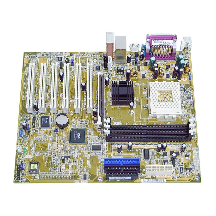
- Page 11 Chapter 1 This chapter gives information about the ASUS A7V8X-X motherboard that came with the system.This chapter includes the motherboard layout, jumper settings, and connector locations. ASUS A7V8X-X Motherboard...
-
Page 12: Welcome
Welcome! Thank you for buying the ASUS The ASUS A7V8X-X motherboard is loaded with the most advanced technologies to deliver the maximum performance for socket A processors. This motherboard is loaded with value-added features for guaranteed consumer satisfaction. Unique ASUS features such as ASUS C.O.P., ASUS C.P.R., ASUS EZFlash, ASUS JumperFree,... -
Page 13: Motherboard Components
Motherboard components Before you install the motherboard, learn about its major components and available features to facilitate the installation and future upgrades. Refer to the succeeding pages for the component descriptions. ASUS A7V8X-X Motherboard... -
Page 14: Core Specifications
PC2100/1600 DDR DIMMs. (Note: PC2700 maximum to 4 banks only. PC3200 maximum to 2 banks only. Visit the ASUS website [www.asus.com] for the latest qualified DDR400 module list.) ATX power connector. This 20-pin connector connects to an ATX +12V power supply. - Page 15 S/PDIF out port. This port connects to external home theater systems for surround sound and enhanced 3D audio when playing DVDs or games. PS/2 keyboard port. This purple 6-pin connector is for a PS/2 keyboard. ASUS A7V8X-X Motherboard 4-Speaker 6-Speaker...
-
Page 16: Special Features
Overheating Protection to prolong the life of the entire system. If the CPU temperature exceeds the set criteria, the PC shuts down automatically. ASUS EZ Flash With ASUS EZ Flash, you can update BIOS before entering operating system. No more DOS-based flash utility and bootable diskette required. SoundMax Digital Audio System (on audio models only) The SoundMax Digital Audio System is the industry’s highest performance and... -
Page 17: Motherboard Layout
PCI Slot 1 A7V8X-X PCI Slot 2 FP_AUDIO PCI Slot 3 Audio Codec PCI Slot 4 PCI Slot 5 ® PCI Slot 6 ASUS A7V8X-X Motherboard 24.4cm (9.6in) CPU_FAN (AGP) VT8235 Chipset CR2032 3V Lithium Cell CMOS Power CLRTC Super... -
Page 18: Before You Proceed
A7V8X-X ® A7V8X-X Onboard LED Install only 1.5V AGP cards on this motherboard to prevent damage to your AGP card or motherboard. SB_PWR Standby... -
Page 19: Motherboard Installation
Place nine (9) screws into the holes indicated by circles to secure the motherboard to the chassis. Do not overtighten the screws! Doing so may damage the motherboard. Place this side towards the rear of the chassis ASUS A7V8X-X Motherboard... -
Page 20: Central Processing Unit (Cpu)
Central Processing Unit (CPU) The motherboard provides a Socket A (462) for CPU installation. AMD processors offer gigahertz speeds to support all the latest computing platforms and applications. The A7V8X-X supports Athlon A7V8X-X ® A7V8X-X Socket A 1.8.1 Installing the CPU Follow these steps to install a CPU: 1. -
Page 21: System Memory
PC3200 maximum to 2 banks only and PC2700 maximum to 4 banks only. 1.10 Expansion slots The A7V8X-X motherboard has six (6) expansion PCI slots and one (1) AGP 8X slot. The following sub-sections describe the slots and the expansion cards that they support. -
Page 22: Standard Interrupt Assignments
+1.5V AGP cards only. When you buy an AGP card, make sure that you ask for one with +1.5V specification. Note the notches on the card golden fingers to ensure that they fit the AGP slot on your motherboard. A7V8X-X ® A7V8X-X Accelerated Graphics Port (AGP ) 1-12 Standard Function — —... -
Page 23: Jumpers
The total current consumed must NOT exceed the power supply capability (+5VSB) whether under normal condition or in sleep mode. A7V8X-X ® A7V8X-X USB Device Wake Up 2. V over-voltage (3-pin OVER_VOLT) CORE When enabled, this jumper allows CPU V... - Page 24 A7V8X-X ® A7V8X-X Clear RTC RAM Setting 4. Keyboard power (3-pin KBPWR) This jumper allows you to enable or disable the keyboard wake-up feature. Set this jumper to pins 2-3 (+5VSB) if you wish to wake up the computer when you press a key on the keyboard (the default value is [Disabled]).
-
Page 25: Connectors
A7V8X-X ® A7V8X-X ATX Power Connectors If you will need to replace the power supply in the future, make sure that your new ATX 12V power supply can provide 8A on the +12V lead and at least 1A on the +5-volt standby lead (+5VSB). - Page 26 For UltraDMA/133/100/66 IDE devices, use an 80-conductor IDE cable. A7V8X-X ® A7V8X-X IDE Connectors MDC header (10-1 pin MDC) This ASUS proprietary modem header accomodates an optional modem module. A7V8X-X ® A7V8X-X MDC Header 1-16 NOTE: Orient the red markings (usually zigzag) on the IDE ribbon cable to PIN 1.
- Page 27 (Pin 5 is removed to prevent incorrect insertion when using ribbon cables with pin 5 plug). A7V8X-X ® A7V8X-X Floppy Disk Drive Connector CPU and Chassis Fan Connectors (3-pin CPU_FAN, CHA_FAN) The two fan connectors support cooling fans of 350mA (4.2 Watts) or a total of 1A (12W) at +12V.
- Page 28 A7V8X-X ® A7V8X-X Front Panel Audio Connector Hard disk connector (2-pin IDE_LED) This 2-pin connector connects to the front panel HD LED and lights up on every read/write activity of any of the disc drives connected to the primary or secondary IDE slots.
- Page 29 A7V8X-X ® A7V8X-X Chassis Alarm Lead 11. GAME/MIDI connector (16-1 pin GAME) (on Audio model only) This connector supports a GAME/MIDI module. If your package came with the optional USB 2.0/GAME module, connect the GAME/MIDI cable to this connector.
-
Page 30: System Panel Connector
This connector accommodates several system front panel functions. A7V8X-X ® A7V8X-X System Panel Connectors • System Power LED Lead (3-1 pin PLED) This 3-1 pin connector connects to the system power LED. The LED lights up when you turn on the system power, and blinks when the system is in sleep mode. - Page 31 Chapter 2 This chapter gives information about the ASUS A7V8X-X Binary Input/Output System (BIOS).This chapter includes updating the BIOS using the ASUS AFLASH BIOS that is bundled with the support CD. ASUS A7V8X-X Motherboard...
-
Page 32: Chapter 2: Bios Information
BIOS later. 2.1.1 Using ASUS EZ Flash to update the BIOS The ASUS EZ Flash feature allows you to easily update the BIOS without having to go through the long process of booting from a diskette and using a DOS-based utility. - Page 33 5. At the prompt, “Please Enter File Name for NEW BIOS: _” name that you downloaded from the ASUS website, then press <Enter>. EZ Flash will automatically access drive A to look for the file name that you typed. When found, the following message appears on screen.
-
Page 34: Using Aflash To Update The Bios
The BIOS information in the above screen is for reference only. What you see on your screen may not be exactly the same as shown. 2.1.2 Using AFLASH to update the BIOS Creating a bootable disk AFLASH.EXE is a Flash Memory Writer utility that updates the BIOS by uploading a new BIOS file to the programmable flash ROM on the motherboard. -
Page 35: Updating The Bios
Careless updating may result to more problems with the motherboard! 1. Download an updated ASUS BIOS file from the Internet (WWW or FTP) (see ASUS CONTACT INFORMATION on page x for details) and save to the boot floppy disk you created earlier. - Page 36 Just repeat the process, and if the problem persists, load the original BIOS file you saved to the boot disk. If the Flash Memory Writer utility is not able to successfully update a complete BIOS file, call the ASUS service center for support.
-
Page 37: Crashfree Bios Feature
1. Turn on the computer, and when prompted, place the bootable floppy disk into the floppy drive, so that the computer boots from the floppy disk. 2. Follow the BIOS update procedure in section “2.1.2 Using AFLASH to update the BIOS.” ASUS A7V8X-X Motherboard... -
Page 38: Bios Setup Program
BIOS Setup program Use the BIOS Setup program when you are installing a motherboard, reconfiguring your system, or prompted to “Run Setup”. This section explains how to configure your system using this utility. Even if you are not prompted to use the Setup program, you may want to change the configuration of your computer in the future. -
Page 39: Legend Bar
Press <Home> to display the first page, press <End> to go to the last page. To exit the help window, press <Enter> or <Esc>. ASUS A7V8X-X Motherboard Function Description Displays the General Help screen from anywhere in... -
Page 40: Main Menu
Sub-menu the fields, use the set default hot key <F5> to load the Setup default values. While moving around through the Setup program, note that explanations appear in the Item Specific Help window located to the right of each menu. This window displays the help text for the currently highlighted field. - Page 41 If you need to erase the CMOS RAM, unplug the all the power cables and remove the button cell battery. Re-install the battery after about 2 seconds, then power up the system. Refer to section “2.1 Managing and updating your BIOS” on how to update the BIOS. ASUS A7V8X-X Motherboard 2-11...
-
Page 42: Primary And Secondary Master/Slave
Halt On [All Errors] This field specifies the types of errors that will cause the system to halt. Configuration options: [All Errors] [No Error] [All but Keyboard] [All but Disk] [All but Disk/Keyboard] Installed Memory [XXX MB] This field automatically displays the amount of conventional memory detected by the system during the boot process. - Page 43 Type field to [User Type HDD] and the Translation Method field to [Manual]. CHS Capacity This field shows the drive’s maximum CHS capacity as calculated by the BIOS based on the drive information you entered. ASUS A7V8X-X Motherboard 2-13...
-
Page 44: Keyboard Features
Maximum LBA Capacity This field shows the drive’s maximum LBA capacity as calculated by the BIOS based on the drive information you entered. Multi-Sector Transfers [Maximum] This option automatically sets the number of sectors per block to the highest number that the drive supports. Note that when this field is automatically configured, the set value may not always be the fastest value for the drive. -
Page 45: Advanced Menu
The [Manual] setting allows you to manually select the core voltage supplied to the CPU (see next item). It is recommended that you keep the default setting [Auto] to allow the system to automatically determine the appropriate CPU core voltage. ASUS A7V8X-X Motherboard 2-15... -
Page 46: Chip Configuration
CPU VCore When the CPU VCore Setting parameter above is set to [Manual], the CPU VCore item allows you to select a specific CPU core voltage. This field is not accessible when the CPU VCore Setting is set to [Auto]. CPU Level 1 Cache, CPU Level 2 Cache [Enabled] These fields allow you to choose from the default [Enabled] or choose [Disabled] to turn on or off the CPU Level 1 and Level 2 built-in cache. - Page 47 When set to [1X Mode], the AGP interface only provides a peak data throughput of 266MB/s even if you are using an AGP 8X card. Configuration options: [Auto] [1X Mode] [2X Mode] [4X Mode] [8X Mode] ASUS A7V8X-X Motherboard 2-17...
- Page 48 AGP Drive Strength [Auto] Configuration options: [Auto] [Manual] AGP Drive N Control [E] Configuration options: [0][1][2][3][4][5][6][7][8][9][A][B][C][D][E][F] AGP Drive P Control [F] Configuration options: [0][1][2][3][4][5][6][7][8][9][A][B][C][D][E][F] AGP performance control [Disabled] Configuration options: [Disabled] [Enabled] AGP Fast Write control [Disabled] Configuration options: [Disabled] [Enabled] Video Memory Cache Mode [UC] USWC (uncacheable, speculative write combining) is a new cache technology for the video memory of the processor.
-
Page 49: I/O Device Configuration
ECP mode. This selection is available only if you select [ECP] or [ECP+EPP] in Parallel Port Mode above. Configuration options: [1] [3] Onboard AC97 Modem Controller [Auto] These fields allow you to enable or disable the onboard AC97 modem controller. Configuration options: [Auto] [Disabled] ASUS A7V8X-X Motherboard 2-19... -
Page 50: Pci Configuration
Onboard AC97 Audio Controller [Auto] These fields allow you to enable or disable the onboard AC97 audio controller. Configuration options: [Auto] [Disabled] Onboard LAN [Enabled] This field allows you to enable or disable the onboard LAN Boot ROM. Configuration options: [Disabled] [Enabled] Onboard Game Port [200H-207H] These fields allow you to set the addresses for the onboard game connectors. -
Page 51: Power Menu
IRQ. Configuration options: [No/ICU] [Yes] Power Menu The Power menu allows you to reduce power consumption. This feature turns off the video display and shuts down the hard disk after a period of inactivity. ASUS A7V8X-X Motherboard 2-21... - Page 52 Power Management [User Defined] This field allows you to activate or deactivate the automatic power saving features. When set to [Disabled], the power management features do not function regardless of the other settings on this menu. The [User Defined] option allows you to set the period of inactivity before the system enters suspend mode.
-
Page 53: Power Up Control
This parameter allows you to use specific keys on the keyboard to turn on the system. This feature requires an ATX power supply that provides at least 1A on the +5VSB lead. Configuration options: [Disabled] [Space Bar] [Ctrl-Esc] [Power Key] ASUS A7V8X-X Motherboard 2-23... -
Page 54: Hardware Monitor
Power On By PS/2 Mouse [Disabled] When set to [Double Click], this parameter allows you to use the PS/2 mouse to turn on the system. This feature requires an ATX power supply that provides at least 1A on the +5VSB lead. Configuration options: [Disabled] [Double Click] Power Up On PCI Card [Disabled] When set to [Enabled], this parameter allows you to turn on the system through a PCI LAN or modem card. -
Page 55: Boot Menu
PCI bus slots instead of using the BIOS. When [Yes] is selected, interrupts may be reassigned by the OS. If you installed a non-PnP OS or if you want to prevent reassigning of interrupt settings, keep the default setting [No]. Configuration options: [No] [Yes] ASUS A7V8X-X Motherboard 2-25... -
Page 56: Exit Menu
Reset Configuration Data [No] The Extended System Configuration Data (ESCD) contain information about non- PnP devices. It also holds the complete record of how the system was configured the last time it was booted. Select [Yes] if you want to clear these data during the Power-On-Self-Test (POST). -
Page 57: Load Setup Defaults
This option saves your selections without exiting the Setup program. You can then return to other menus and make further changes. After you select this option, a confirmation window appears. Select [Yes] to save any changes to the non-volatile RAM. ASUS A7V8X-X Motherboard 2-27... - Page 58 2-28 Chapter 2: BIOS Information...
- Page 59 Chapter 3 This chapter helps you power up your system and install drivers and utilities that came with the support CD. ASUS A7V8X-X Motherboard...
-
Page 60: Install An Operating System
Install an operating system The A7V8X-X motherboard supports Windows ME/NT/2000/XP operating systems (OS). Always install the latest OS version and corresponding updates so you can maximize the features of your hardware. Because motherboard settings and hardware options vary, use the setup procedures presented in this chapter for general reference only. -
Page 61: Drivers Menu
ASUS PC Probe Install utility that can monitor Fan, Speed, Voltage, and CPU temperature. ASUS Update Installs utility to download and update motherboard BIOS & drivers. Microsoft DirectX 8.1 Driver This item installs the Microsoft V8.1 driver. ASUS A7V8X-X Motherboard... -
Page 62: Asus Contact Information
E-Color 3Deep This item installs application to optimize 3D graphics output. 3.2.4 ASUS Contact Information Clicking the ASUS Contact Information tab displays as stated. You may also find this information on page viii of this user guide. 3.2.5 Multi-channel audio feature The ADI AD1980 AC ‘97 audio CODEC provides 6-channel audio capability. - Page 63 9. Click the Close button when done. 10. The MIDI Music Synthesizer screen allows you to select a setting for the MIDI. ASUS A7V8X-X Motherboard Sound MAX Digital Integrated Audio icon Audio path indicator...
- Page 64 2. Check the box opposite Mic2 Select to enable the front panel microphone, if you installed a front panel audio device such as the ASUS iPanel. 3. Click Close to effect the new setting. The rear panel microphone is automatically disabled when you enable the front panel microphone.